Abstract
Culture of cells as three-dimensional (3D) aggregates, named spheroids, possesses great potential to improve in vitro cell models for basic biomedical research. However, such cell spheroid models are often complicated, cumbersome, and expensive compared to conventional Petri-dish cell cultures. In this work, we developed a simple microfluidic device for cell spheroid formation, culture, and harvesting. Using this device, cells could form uniformly sized spheroids due to strong cell–cell interactions and the spatial confinement of microfluidic culture chambers. We demonstrated cell spheroid formation and culture in the designed devices using embryonic stem cells, carcinoma cells, and fibroblasts. We further scaled up the device capable of simultaneously forming and culturing 5000 spheroids in a single chip. Finally, we demonstrated harvesting of the cultured spheroids from the device with a simple setup. The harvested spheroids possess great integrity, and the cells can be exploited for further flow cytometry assays due to the ample cell numbers.
INTRODUCTION
Moving from two-dimensional cell monolayer to three-dimensional (3D) cell culture is motivated by bridging the gap between in vitro cell culture and living tissues.1 Cell spheroid, culture of cell aggregates without any scaffold or physical support, is an example of 3D cell culture models.2 A multicellular spheroid has gradients in nutrients, metabolites, catabolites, and oxygen along the spheroid radius. As a result, cell spheroids are concentric arrangement of heterogeneous cell population with different cellular activities, proliferation and differentiation, which can better represent in vivo physiological situation in vitro.3 For example, 3D cell spheroid model is receiving increasing attraction to study the influence of tumor microenvironments and testing drugs under more physiological meaningful conditions.4 Furthermore, cell spheroid culture is also drawing attentions for embryonic stem (ES) cell research. ES cells represent a promising renewable cell source because they are capable of self-renewal and extensive cell proliferation maintaining the stemness. The ES cell differentiation is often initiated by generation of embryoid bodies (EBs), which are 3D aggregates of ES cells. The EB size is a crucial parameter controlling the differentiation of ES cells.5, 6, 7 Therefore, spheroid culture of cells is also important to study the early embryogenesis for developmental biology.8
Formation of spheroids occurs spontaneously in an environment where cell–cell interaction is stronger than cell–substrate interaction. Typical methods for spheroid formation include hanging drops, culture of cells on non-adherent surfaces, spinner flask, and NASA rotary cell culture system.9, 10 However, traditional spheroid formation methods usually produce various sized spheroids, which is inconvenient for many biomedical applications. For instance, spheroids with various sizes are unable to provide reliable information for drug testing due to the size-dependent resistance of tumor spheroids.
In recent decades, various microfluidic cell culture devices have been developed.11, 12, 13, 14, 15, 16, 17 Microfluidics is capable of better controlling flows in spatial and temporal domains, which allows reconstituting precise and more in vivo-like microenvironments to study cell behaviors. Using microfluidic devices, cell spheroids can be cultured in a normal incubator and a particular spheroid can be monitored for certain periods of time. Recently, researchers have developed various spheroid formation and culture devices based on microfluidics techniques.18, 19, 20, 21, 22, 23, 24, 25, 26, 27, 28, 29, 30, 31, 32 A multilayer microfluidic device with a porous membrane was employed to achieve both the spheroid formation and in-situ culture.24 A microfluidic array platform containing concave microwells and flat cell culture chambers for EB formation and its culture was also developed.25 Formation of cell spheroids using gravity oriented microfluidic device was also introduced.26 However, current spheroid culture devices possess some drawbacks that retard their practical use. The multilayer device with semi-transparent membranes suffers from problems of high fidelity imaging and real time monitoring.24 In addition, the spheroids cannot be easily harvested from the devices due to their channel designs without additional instrumentation.26, 29 The conventional analysis techniques include fluorescence staining using the antibody tagged fluorophores, but most of the microfluidic devices cannot form and culture a large number of cell spheroids with uniform size and harvest them out for further conventional analysis, such as flow cytometry or western blot.
In this paper, we develop a bi-layer microfluidic device with polydimethylsiloxane (PDMS) for cell spheroid formation and culture. PDMS is broadly used to construct various microfluidic devices for cell culture due to its excellent optical transparency, manufacturability, high gas permeability and biocompatibility.33 The bottom layer of this device is equipped with several rows of cubical cavities as cell culture chambers, and the top layer has a channel covering all the cell culture chambers. We culture the spheroids formed from various types of cells for more than 72 h in this device. Using the same principle, we scaled up the device to form and culture more than 5000 uniformly sized spheroids, which is approximately 100 times more than those formed in most microfluidic devices, in a single chip. We harvested the 3D spheroids from the device in an efficient manner by controlling the flow rate through the top channel of the device with great integrity without additional instrumentation and tedious procedures. The cells, obtained by dissociating spheroids, were exploited for flow cytometry for demonstration. The developed microfluidic device offers a simple tool for formation and culture of uniform spheroids with minimal instrumentation and simple setup. Moreover, due to the capability of scaling up, the device provides a promising technique to further study cellular behaviors, including cell proliferation, migration, and apoptosis in 3D spheroids under precise mechanical, chemical and gaseous microenvironments, with aids of conventional biochemical analysis methods.
MATERIALS AND METHOD
Microfluidic cell culture device design and fabrication
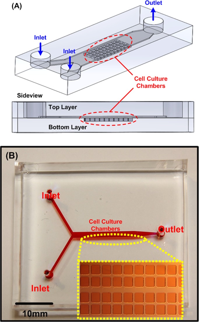
The device was constructed using two PDMS layers: the bottom layer with cell culture chambers and a channel at the top layer covering the cell culture chambers, as shown in Fig. 1. We used the well-developed soft lithography replica molding process to fabricate this device.34 A silicon wafer with positive relief features was exploited as a mold. The mold was fabricated using a negative tone photoresist (SU-8 2050, Micro Chem Co., Newton, MA) patterned by conventional photolithography. The fabricated mold was then silanized with 1H, 1H, 2H, 2H-perfluorooctyltrichlorosilane (78560-45-9, AlfaAesar, Ward Hill, MA) in a desiccator for more than 30 min at room temperature to prevent undesired bonding of PDMS to the mold. PDMS prepolymer (Sylgard 184, Dow Corning Co., Midland, MI) with 1: 10 (v/v) curing agent to base ratio was poured on the mold and cured at 60 °C for more than 4 h. After curing, the interconnection holes were punched using a biopsy punch with a diameter of 1.5 mm at the top layer. The bottom layer was aligned and irreversibly bonded with the top layer using oxygen plasma surface treatment (PX-250, Nordson MARCH Co., Concord, CA) at 90 W for 40 s. The PDMS device was then cured in a 60 °C oven for more than 2 h to promote the bonding and assure full curing of the PDMS to enhance the cell compatibility.
Figure 1.
(a) Illustrations of the developed bi-layer PDMS microfluidic device for spheroid formation and culture. (b) Photo of the fabricated microfluidic device filled with food dyes. The inset shows the microscopic image of the cell culture chambers.
Numerical simulation
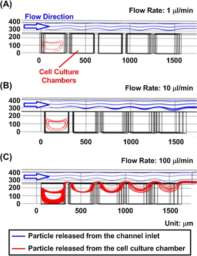
In order to investigate the flow profiles within the designed device for cell manipulation and medium exchange, a 3D finite element analysis (FEA) model was constructed using COMSOL Multiphysics software (Ver. 4.2, COMSOL Inc., Burlington, MA).35, 36 In the simulation, material properties of water were exploited. Since the cells have relatively small radius (usually less than 20 μm) and similar densities to water, the settling speed, which results from the balance between gravity, buoyancy, and drag forces, is small for cells flowing inside the channel.37, 38 Therefore, to investigate single cell movements inside the channel, the flow profile was studied using massless particles introduced at an interval of 1 s from the cell culture chamber and from the channel inlet for simplification. Figure 2 shows the flow trajectories of particles released from the channel inlet and cell culture chambers using the particle tracking function with flow rates of 1, 10, and 100 μl/min, respectively. The results show that the particles released from the chamber were trapped inside following an elliptical path at the flow rates of 1 μl/min and 10 μl/min. In contrast, the particles were flushed out of the chamber when the flow rate was increased to 100 μl/min. Therefore, cell suspension introduced into the device with low flow rates can be utilized to seed cells inside the cell culture chambers, and the cells can remain in the chambers. These simulation results are experimentally verified with cells in the designed microfluidic device (videos in the supplementary material39).
Figure 2.
Simulated particle trajectories inside the microfluidic device with various input flow rates. (a) and (b) At the flow rates of 1 and 10 μl/min the particles are trapped inside the cell culture chambers. (c) While the flow rate is increased to 100 μl/min, the particles are flushed out of the cell culture chamber.
For spheroid movement simulation, we exploited particles with volumes and masses in the model. In the simulation, 75 μm-radius perfect spherical shape particles with density of 1100 kg/m3 were used to approximate the spheroids cultured in the device.38 The simulation results (Fig. S1 in the supplementary material39) show that the gravity force is large enough to make spheroids trapped and remain inside the cell culture chambers at flow rates of 50 and 100 μl/min. While the flow rate is increased to 1000 μl/min, drag driven flows are strong enough to create secondary flows in the cell culture chambers to flush out the spheroids. The simulation results are also experimentally verified and described in Fig. S2 in the supplementary material.39 As a result, the cell spheroids could be cultured inside the chambers with continuous medium perfusion by using the low flow rate (e.g. 1 μl/min), and the spheroids could be harvested from the device by increasing the flow rate (e.g. about 1000 μl/min).
Cell culture
To demonstrate spheroid formation and culture capabilities of the developed device, three types of cells, including ES cell, carcinoma cell, and fibroblast, were cultured in this study. The specific cell lines used in the experiments were murine ES cell (ES-D3, 60205, Bioresource Collection and Research Center, Hsinchu, Taiwan) transfected with Oct4-GFP (hOct4-GFP, Plasmid 21153, Addgene, Cambridge, MA), human hepatocellular carcinoma cell (HepG2, 60025, Bioresource Collection and Research Center), and African green monkey kidney epithelial fibroblast (COS-7, 60094, Bioresource Collection and Research Center). The ES-D3 cells were cultured with growth medium composed of Dulbecco's Modified Eagle's Medium (DMEM) (Gibco 10566, Invitrogen Co., Carlsbad, CA) with 15% v/v fetal bovine serum (Gibco 10082, Invitrogen), 1% v/v Antibiotic-Antimycotic (Gibco 15240, Invitrogen) 0.1 mM 2-mercaptoethanol (M7522, Sigma-Aldrich), 0.02% v/v sodium pyruvate (Gibco 11360, Invitrogen), 1% v/v non-essential amino acids (Gibco 11140, Invitrogen) and 1000 U/ml ESGRO (Chemicon ESG1106, Millipore). The cell stocks were maintained in 1% Gelatin (G1890, Sigma-Aldrich)-coated Petri dishes at 37 °C in a humidified incubator with 5% CO2. HepG2 and COS-7 cell lines were cultured using growth medium composed of DMEM (Gibco 10566, Invitrogen) with 10% v/v fetal bovine serum, 1% Antibiotic-Antimycotic, 1% sodium pyruvate and 1% non-essential amino acids. The stocks were maintained under 5% CO2 in T25 cell culture flasks (Nunc 156367, Thermo Scientific Inc., Rochester, NY), and passaged by dissociation with 0.25% trypsin-EDTA (Gibco 25200, Invitrogen). Cell suspensions for the experiments were made by centrifugation of dissociated cells at 1000 rpm for 5 min at room temperature.
Cell spheroid formation and culture
Before cell experiments, the device was oxidized in oxygen plasma for 5 min to make the PDMS surface hydrophilic. Afterward, 1% w/v Synperonic® F-108 (07579, Fluka, SIGMA- ALDRICH, Co., St. Louis, MO) was introduced into the channel and incubated overnight to make the device resistant to cell adhesion. Prior to cell loading, the device was sterilized under UV light for 1 h. Excess Synperonic® F-108 was washed out with the culture medium. For the formation and culture of EBs, the top channel with length, width, and height of 25 × 1.2 × 0.15 mm3 and the culture chambers with length, width, and depth of 150 × 150 × 250 μm3 and the distance between neighboring chambers of 200 μm on the bottom layer were used (total 90 chambers). A 5 μl ES cell suspension with density of 107 cells/ml was introduced from the top channel inlet with a flow rate of approximately 1 μl/min estimated from microscopic observation. The device was kept in a humidified incubator with 5% CO2 at 37 °C. Due to the gravity-driven flow, the cells settled in the cell culture chambers. Owing to the strong cell–cell interaction and non-adhesive surface of the device, the ES cells aggregated with each other within 16 h. Similarly, HepG2 and COS-7 cell spheroids were formed inside the device by introducing 107 and 105 cells/ml of volume 5 μl into the similar top channel, and the cell culture chambers with length, width, and depth of 250 × 250 × 250 μm3 and the distances between neighboring chambers of 75 μm and 200 μm, respectively (total 150 and 90 chambers). The culture medium was exchanged after 48 h using a normal pipette with the flow rate of approximately 20 μl/min. The spheroid size was characterized with ImageJ (1.46 r, NIH, Bethesda, MD). The two dimensional area was outlined manually to estimate the diameters, assuming the projective shape of the spheroids as a circle. Using the same principle, we scaled up our device to prepare 5000 uniform-sized spheroids (top channel with width of 1.4 mm and height of 150 μm; bottom channel with cell culture chamber size of 200 × 200 × 250 μm3; the distance between neighboring chambers is 90 μm).
Harvesting spheroids
To demonstrate the spheroid harvesting from the device, another hole before the outlet in the top channel was created by using a 2 mm-diameter biopsy punch. We prepared the additional outlet to avoid the cell aggregation at original inlets and outlets. We added 5 ml culture medium from both inlets to flush the 3D spheroids out of the culture chambers. The spheroids were then pipetted out from the new hole (approximate flow rate of 1000 μl/min) with minimum disturbance to maximize the spheroid harvesting yield. It takes approximately 10 min for the entire process of harvesting.
Flow cytometry analysis
The device design was further scaled up to form and culture more than 5000 HepG2 spheroids in a single chip, and the spheroids were harvested out of the device using the aforementioned fluid flow mechanism. The spheroids were then dissociated into single cells using Trypsin-EDTA 0.25% for 8 min. In the experiments, cell viability flow cytometry analysis was performed as a demonstration. Single cell suspension (1.5 × 10⁵ cells/ml) of 1 ml was stained with 2 μl Calcein AM (50 μM) (live stain) for 20 min in room temperature, protected from light. The cells were further incubated for 10 min with 7-Amino-ActinomycinD (7-AAD, 559925, BD Pharmingen) 5 μl (0.25 μg)/test (dead stain) with 1.5 × 10⁵ cells in 100 μl PBS. The stained cells were analyzed by BD FACS Calibur (within one hour) using 488 nm excitation and measuring green fluorescence emission for Calcein AM (530 nm/30 nm band pass) and red fluorescence emission for 7-AAD (650 nm long pass).
RESULTS AND DISCUSSIONS
Formation of 3D spheroids and culture in the device
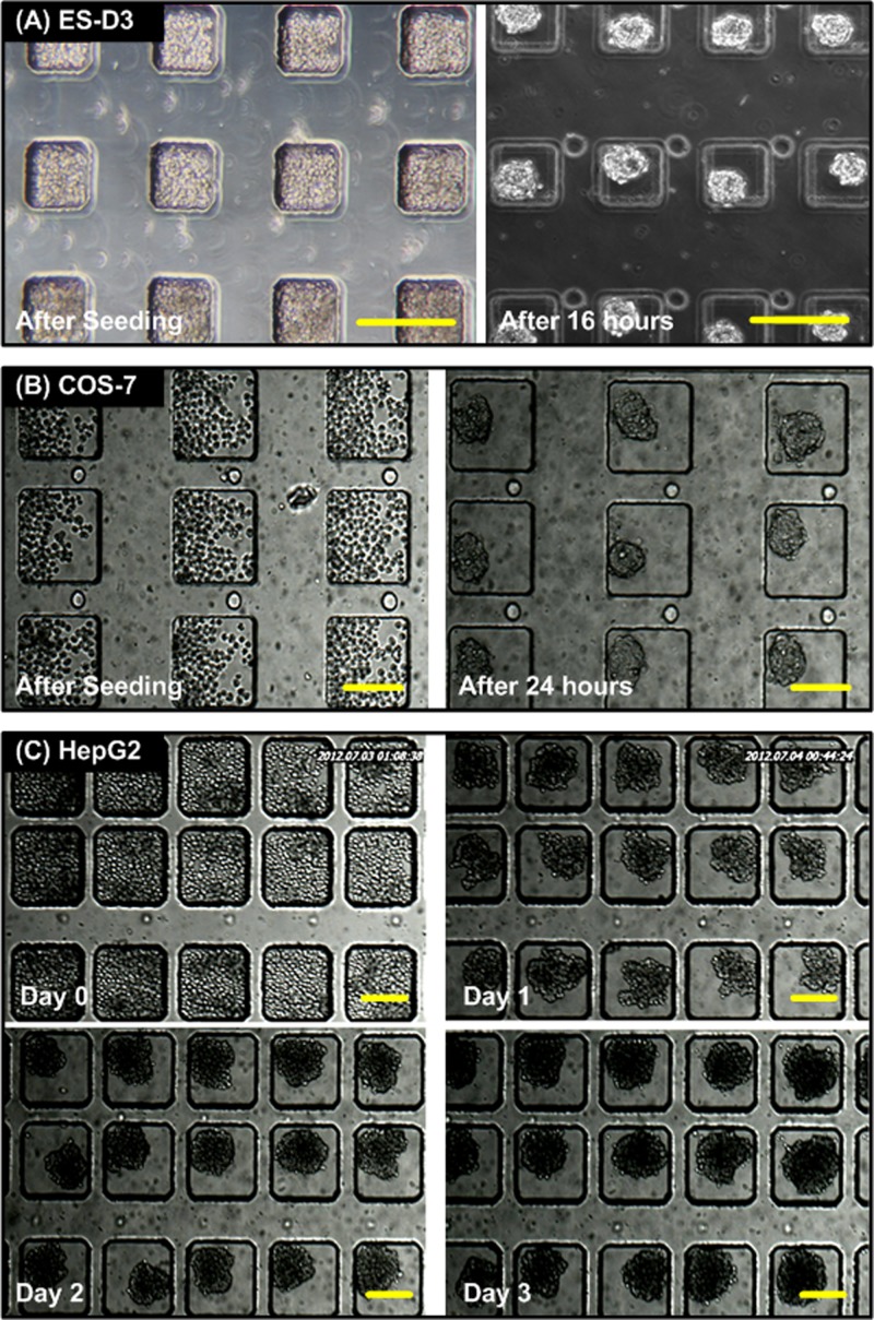
Figure 3 shows the bright field images of spheroids formed using various types of cells inside the microfluidic devices. Figures 3a, 3b show that the ES-D3 and COS-7 cells are capable of aggregating and forming uniform-sized cell spheroids after 16- and 24-h culture, respectively. In order to demonstrate long-term culture in the device, HepG2 cells were introduced into the device and cultured for 4 days. Figure 3c shows the bright field images captured at different days. The results show that HepG2 cells could aggregate to form a 3D structure within 1 day, and the shape of HepG2 spheroids was more irregular compared to those of ES-D3 and COS-7 cells. The growth of spheroids in their 2D sizes was observed during the culture period. The increase of spheroid size suggested that the spheroid could be successfully cultured inside the device. Furthermore, the culture medium could be easily refreshed through the microfluidic channel in the top layer using a commonly used pipette.
Figure 3.
Microscopic images of cell spheroid formation and culture inside the microfluidic devices. (a) ES-D3 cells right after seeding and after 16-h culture. (c) COS-7 cells right after seeding and after 24-h culture. (c) 4-day culture of HepG2 cells inside the device. The HepG2 cells aggregate and form spheroids after 1-day culture. The sizes of the spheroids are increased during the culture period. Scale bar is 200 μm.
Fluorescence stain, size distribution, and scale up the device
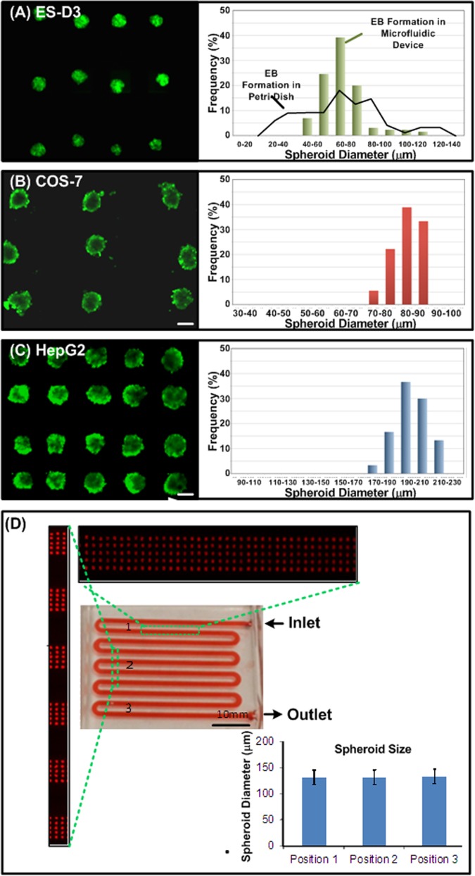
Figure 4 shows the fluorescence images and the size distributions of the spheroids formed in the microfluidic devices. Figure 4a shows the fluorescence images of EBs formed by Oct-4 GFP transfected ES-D3 cells after 16 h of culture. The bright GFP signal suggests that the stemness of EBs was well maintained during the spheroid formation and culture process. Furthermore, the histogram shows that the spheroids formed in the device exhibit a more uniform size distribution compared to those formed in a Petri dish with non-adherent surface coating. The average diameter of the EBs in the device is approximately 80 μm. With the uniform size distribution, the formed EBs can be further utilized to statistically study the size dependent differentiation.
Figure 4.
Fluorescence microscopic images and size distributions of spheroids formed and cultured inside the microfluidic device. (a) EBs formed by Oct-4 GFP transfected ES-D3 cells show their well-maintained stemness. The histogram shows the more uniform size distribution of the EBs formed in the device compared to those formed in a Petri dish after 16-h culture. (b) and (c) Calcein AM-stained COS-7 (after 24-h culture) and HepG2 (at day 3) spheroids formed and cultured in the developed devices, respectively. The histograms show uniform spheroid size distributions of both cell types. (D) Photo of a device culturing 5000 DsRed-HepG2 spheroids for 3 days. Scale bar is 100 μm.
In order to estimate the cell viability in the device, Calcein AM (live stain) fluorescence staining was performed on the COS-7 and HepG2 spheroids in the experiments. Figures 4b, 4c show the fluorescence images and size distributions of the COS-7 and HepG2 spheroids, respectively. The bright fluorescence signals suggest that the cells remain their integrity after forming 3D spheroid structures inside the device. In addition, the histograms show both cell types could form uniform sized spheroids in the microfluidic devices. The average diameters of COS-7 and HepG2 spheroids are 80 and 200 μm with standard deviations of 4 and 10 μm, respectively. For the conventional analysis system, like flow cytometry, requires a large number of cells. The present microfluidic devices are not capable of preparing large number of uniformly sized spheroids in the same device at a time. Figure 4d shows the selective view of HepG2 (DsRed) spheroids in the device capable of formation and culture of 5000 spheroids in a single device at day 3. To quantify the homogeneity of the spheroid sizes from upstream to downstream area, we estimated the average spheroid sizes and their standard deviations by analyzing the fluorescence microscopic images. The average spheroid diameters in up-, mid-, and down-stream areas are 132 μm, 131 μm and 133 μm, respectively, with standard deviation less than 13 μm (n = 15). We also performed statistical analysis (unpaired, two-tailed Student's t-test), and the results show that there is no difference between the spheroids formed in different areas in the device (p > 0.2). Consequently, this device could offer statistical study in various biomedical analyses, compared to present in vitro 3D cell models in microfluidic devices.
Harvesting of 3D spheroids and flow cytometry analysis
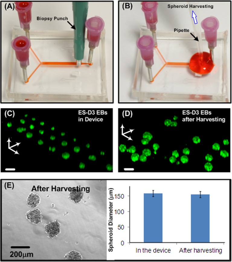
For further biochemical assays, harvesting the spheroids from the microfluidic device is essential. In order to efficiently harvest the spheroids, a procedure based on the aforementioned numerical simulation results was developed. Figures 5a, 5b show the operation procedures of the spheroid harvesting. First, an additional outlet was made using a 2 mm-diameter biopsy punch, as shown in Figure 5a. The cell spheroids were then collected using a normal micro-pipette as shown in Figure 5b. The pipette introduced flow inside the microfluidic channel provided a sufficiently high flow rate that flushed out the spheroids in the culture chambers. In order to investigate the spheroid integrity before and after the harvesting process, 3D images of ES-D3 spheroids with Oct-4 GFP before and after harvesting were obtained by a scanning confocal microscope (TCS SP5, Leica), as shown in Figures 5c, 5d. From the 3D images, the shape of the cultured spheroids was confirmed to be spherical and the stemness was maintained. Also, the 3D structure of the spheroids after harvesting is similar to that in the microfluidic device. Therefore, the harvested EBs might be used for further differentiation experiment or other biochemical assays. In addition, we also performed size analysis on the HepG2 spheroids before and after harvesting from the device as shown in the Fig. 5e. The average diameters of the HepG2 spheroids before and after the harvesting are 157 μm and 154 μm with standard deviations of 12 μm and 9 μm (n = 10), respectively, and there is no statistical difference between the two results (p > 0.1). The results demonstrate that the spheroids possess great integrity and similar sizes after harvesting from the device. In addition, we characterize the spheroid-harvesting yield of the device culturing 5000 spheroids. We performed spheroid harvesting according to the aforementioned procedure, and counted the spheroids still trapped inside the cell culture chambers after the harvesting for three different devices. The resulted harvesting yield is 96.8 ± 0.7% (mean ± standard deviation), which suggests the highly efficient harvesting performance of the device.
Figure 5.
(a) and (b) Procedures to harvest cultured spheroids from the microfluidic device using a biopsy punch and a pipette. (c) Confocal microscopic image of Oct-4 GFP EBs formed and cultured in a microfluidic device. (d) Confocal microscopic image of Oct-4 GFP EBs harvested from a microfluidic device at day 2. Scale bar is 150 μm. (e) HepG2 (at day 3) spheroids harvested out from the device and quantitative size distribution before and after the harvesting.
Flow cytometry analysis
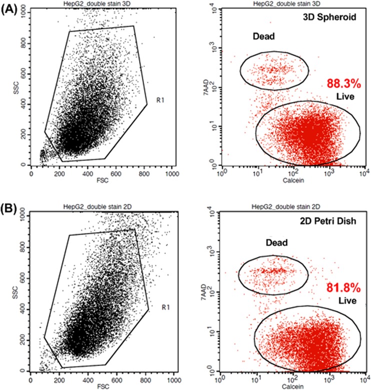
Figure 6a shows the flow cytometry analysis of viability of HepG2 spheroids cultured for 72 h. The left panel of Figure 6a shows the FSC and SSC plot with the gate to avoid debris. In the histogram (right panel), the Calcein AM signal with live cells is at the lower right part and 7-AAD signal with dead cells is at upper left part. The histogram suggests that 88.3% of the cells are alive, which is similar to those cultured in a 2D Petri dish with the viability of 81.8% as shown in Figure 6b. In addition, from the forward and side scattering plot, we do not observe significant differences between two culture methods. To further confirm the cell viability of spheroid culture, we prepared HepG2 spheroids using a hanging drop plate.4 The HepG2 spheroids with similar sizes (∼300 cells per drop) were formed in 15 μl drops according to the reported protocols. The spheroids were harvested after 3-day culture, and viability of the cells obtained by dissociating the spheroids was estimated using LIVE/DEAD Viability/Cytotoxicity Kit for mammalian cells (L3224, Invitrogen). The cell viability of the cells harvested from the spheroids cultured by the hanging drop method is about 83.0%, which is similar to that of the cells dissociated from the spheroids harvested from the device. The results suggest that the harvesting process utilized in this paper does not affect cell viabilities, and the shear stress effect is negligible in the static culture condition used in our device. In this microfluidic device we can culture a large number of uniform spheroids with minimum amount of culture media for at least 3 days with great viability.
Figure 6.
(a) Flow cytometry analysis of dissociated HepG2 (without DsRed) spheroids. FSC, SSC plot and gate (left). Viability analysis using Calcein AM and 7-AAD (right) for HepG2 spheroids cultured for 3 days in the microfluidic device. (b) Flow cytometry analysis of HepG2 cultured in T75 flask for 3 days.
CONCLUSION
In the present work, we report a microfluidic device for uniformly sized cell spheroid formation, culture, and harvesting. The device was composed of two PDMS layers, and the flow fields within the microfluidic channel were numerically simulated to optimize the operations of the device. The cell spheroids formed inside the device can be cultured later can be harvested from the device for further analysis while introducing a flow with much higher flow rate (approximately 1000 μl/min). Various types of cells, including ES cell, carcinoma cell, and fibroblast, are tested to confirm the device compatibility to live cells. We also scale up the device to form 5000 uniform spheroids using the same principle. Furthermore, we harvested the spheroids out of the device without additional instrumentation or tedious procedure, and the cells maintain great integrity and viability. The cells from dissociated spheroids were analyzed in flow cytometry to demonstrate that we were able to collect enough cells to study using conventional analysis methods. With the simple fabrication, operation, and functionalities, the developed microfluidic device provides a useful platform for constructing in vitro cell culture models in the form of spheroids. Moreover, with the great microenvironment controllability provided by microfluidics, the device may pave a way for researchers to investigate the cellular responses under more physiologically relevant conditions in various biomedical applications.
ACKNOWLEDGMENTS
This work was supported by the National Health Research Institutes (NHRI) in Taiwan under Career Development Grant (CDG) (EX102-10021EC), National Science Council (NSC) in Taiwan (NSC-100-2221-E-001-002, NSC-100-2112-M-001-022-MY3, and NSC-101-2628-E-001-002-MY3), and the Academia Sinica Research Program on Nanoscience and Nanotechnology.
References
- Pampaloni F., Reynaud E., and Stelzer E., Nat. Rev. Mol. Cell. Biol. 8, 839 (2007). 10.1038/nrm2236 [DOI] [PubMed] [Google Scholar]
- Bartosh T., Ylöstalo J., Mohammadipoor A., Bazhanov N., Coble K., Claypool K., Lee R., Choi H., and Prockop D., Proc. Natl. Acad. Sci. U.S.A. 107, 13724 (2010). 10.1073/pnas.1008117107 [DOI] [PMC free article] [PubMed] [Google Scholar]
- Sutherland R., Science 240, 177 (1988). 10.1126/science.2451290 [DOI] [PubMed] [Google Scholar]
- Tung Y.-C., Hsiao A., Allen S., Torisawa Y., Ho M., and Takayama S., Analyst 136, 473 (2011). 10.1039/c0an00609b [DOI] [PMC free article] [PubMed] [Google Scholar]
- Hwang Y., Chung B., Ortmann D., Hattori N., Moeller H., and Khademhosseini A., Proc. Natl. Acad. Sci. U.S.A. 106, 16978(2009). 10.1073/pnas.0905550106 [DOI] [PMC free article] [PubMed] [Google Scholar]
- Dang S., Gerecht-Nir S., Chen J., Itskovitz-Eldor J., and Zandastra P. W., Stem Cells 22, 275 (2004). 10.1634/stemcells.22-3-275 [DOI] [PubMed] [Google Scholar]
- Ng E., Davis R., Azzola L., Stanley E., and Elefanty A., Blood 106, 1601(2005). 10.1182/blood-2005-03-0987 [DOI] [PubMed] [Google Scholar]
- Prudhomme W., Daley G., Zandstra P., and Lauffenburger D., Proc. Natl. Acad. Sci. U.S.A. 101, 2900 (2004). 10.1073/pnas.0308768101 [DOI] [PMC free article] [PubMed] [Google Scholar]
- Lin R. and Chang H., Biotechnology. J. 3, 1172 (2008). 10.1002/biot.200700228 [DOI] [PubMed] [Google Scholar]
- Frieddrich J., Ebner R., and Kunz-schughart L., Int. J. Radiat. Biol. 83, 849 (2007). 10.1080/09553000701727531 [DOI] [PubMed] [Google Scholar]
- Hung P., Lee P., Sabounchi P., Lin R., and Lee L. P., Biotechnol. Bioeng. 89, 1 (2005). 10.1002/bit.20289 [DOI] [PubMed] [Google Scholar]
- Dittrich P. and Manz A., Nat. Rev. Drug. Discov. 5, 210 (2006). 10.1038/nrd1985 [DOI] [PubMed] [Google Scholar]
- Yeon J. and Park J., Biochip. J. 1, 17 (2007). [Google Scholar]
- Young E. and Beebe D., Chem. Soc. Rev. 39, 1036 (2010). 10.1039/b909900j [DOI] [PMC free article] [PubMed] [Google Scholar]
- Douville N., Zamankhan P., Tung Y.-C., Li R., Vaughan B., White J., Grotberg J., and Takayama S., Lab Chip 11, 609 (2011). 10.1039/c0lc00251h [DOI] [PubMed] [Google Scholar]
- Chen Y.-A., King A. D., Shih H.-C., Peng C.-C., Wu C.-Y., Liao W.-H., and Tung Y.-C., Lab Chip 11, 3626 (2011). 10.1039/c1lc20325h [DOI] [PubMed] [Google Scholar]
- Ziolkowska K., Jedrych E., Kwapiszewski R., Lopacinska J., Skolimowski M., and Chudy M., Sens. Actuators B 145, 533 (2010). 10.1016/j.snb.2009.11.010 [DOI] [Google Scholar]
- Hsiao A., Torisawa Y., Tung Y.-C., Sud S., Taichman R., Pienta K., and Takayama S., Biomaterials 30, 3020 (2009). 10.1016/j.biomaterials.2009.02.047 [DOI] [PMC free article] [PubMed] [Google Scholar]
- Torisawa Y., Takagi A., Nahimoto Y., Yasukawa T., Shiku H., and Matsue T., Biomaterials 28, 559 (2007). 10.1016/j.biomaterials.2006.08.054 [DOI] [PubMed] [Google Scholar]
- Wu L., Di Carlo D., and Lee L., Biomed. Microdevices 10, 197 (2008). 10.1007/s10544-007-9125-8 [DOI] [PubMed] [Google Scholar]
- Toh Y., Zhang C., Zhang J., Khong Y., Chang S., and Samper V., Lab Chip 7, 302(2007). 10.1039/b614872g [DOI] [PubMed] [Google Scholar]
- Ziółkowska K., Kwapiszewski R., Stelmachowska A., Chudy M., Dybko A., and Brzózka Z., Sens. Actuators, B 173, 908 (2012). 10.1016/j.snb.2012.07.045 [DOI] [Google Scholar]
- Anada T., Fukuda J., Sai Y., and Suzuki O., Biomaterials 33, 8430 (2012). 10.1016/j.biomaterials.2012.08.040 [DOI] [PubMed] [Google Scholar]
- Torisawa Y., Chueh B., Huh D., Ramamurthy P., Roth T., Barald K., and Takayama S., Lab Chip 7, 770 (2007). 10.1039/b618439a [DOI] [PubMed] [Google Scholar]
- Kang E., Choi Y., Jun Y., Chung B. G., and Lee S., Lab Chip 10, 2651(2010). 10.1039/c0lc00005a [DOI] [PubMed] [Google Scholar]
- Lee K., Kim C., Young Yang J., Lee H., Ahn B., Xu L., Kang J. Y., and Oh K. W., Biomicrofluidics 6, 014114(2012). 10.1063/1.3687409 [DOI] [PMC free article] [PubMed] [Google Scholar]
- Agastin S., Giang U., Geng Y., Delouise L., and King M., Biomicrofludics 5, 024110 (2011). 10.1063/1.3596530 [DOI] [PMC free article] [PubMed] [Google Scholar]
- Kim T. and Cho Y., Lab Chip 11, 1825 (2011). 10.1039/C1LC20234K [DOI] [PubMed] [Google Scholar]
- Jin H., Cho Y., Gu J., Kim J., and Oh Y., Lab Chip 11, 115 (2011). 10.1039/c0lc00134a [DOI] [PubMed] [Google Scholar]
- Okuyama T., Yamazoe H., Mochizuki N., Khademhosseini A., Suzuki H., and Fukuda J., J. Biosci. Bioeng. 110, 572 (2010). 10.1016/j.jbiosc.2010.05.013 [DOI] [PubMed] [Google Scholar]
- Fukuda J. and Nakazawa K., Biomicrofluidics 5, 022205 (2011). 10.1063/1.3576905 [DOI] [PMC free article] [PubMed] [Google Scholar]
- Jeong G., Jun Y., Song J., Shin S., and Lee S., Lab Chip 12, 159 (2012). 10.1039/c1lc20619b [DOI] [PubMed] [Google Scholar]
- Eddings M. and Gale B., J. Micromech. Microeng. 16, 2396 (2006). 10.1088/0960-1317/16/11/021 [DOI] [Google Scholar]
- Friend J. and Yeo L., Biomicrofluidics 4, 026502 (2010). 10.1063/1.3259624 [DOI] [PMC free article] [PubMed] [Google Scholar]
- Cioffi M., Moretti M., Manbachi A., Chung B., Khademhosseini A., and Dubini G., Biomed. Microdevices 12, 619 (2010). 10.1007/s10544-010-9414-5 [DOI] [PMC free article] [PubMed] [Google Scholar]
- Khabiry M., Chung B., Hancock M., Soundararajan H., Du Y., Cropek D., Lee W., and Khademhosseini A., Small 5, 1186 (2009). [DOI] [PMC free article] [PubMed] [Google Scholar]
- Rhodes M., Introduction to Particle Technology, 2nd ed. (John Wiley & Sons, Inc., Hoboken, NJ, 2008). [Google Scholar]
- Grover W. H., Bryan A. K., Diez-Silva M., Suresh S., Higgins J. M., and Manalis S. R., Proc. Natl. Acad. Sci. U.S.A. 108, 10992 (2011). 10.1073/pnas.1104651108 [DOI] [PMC free article] [PubMed] [Google Scholar]
- See supplementary material at http://dx.doi.org/10.1063/1.4824480 for videos demonstrating flow characteristics of cells within the microfluidic channels at various flow rates, and figures of numerical simulation and experimental characterization of spheroid movements inside the device.


