Abstract
We demonstrate the optical orbital angular momentum conservation during the transfer process from subwavelength plasmonic vortex lens (PVLs) to light and the generating process of surface plasmon polaritons (SPPs). Illuminating plasmonic vortex lenses with beams carrying optical orbital angular momentum, the SP vortices with orbital angular momentum were generated and inherit the optical angular momentum of light beams and PVLs. The angular momentum of twisting SP electromagnetic field is tunable by the twisted metal/dielectric interfaces of PVLs and angular momentum of illuminating singular light. This work may open the door for several possible applications of SP vortices in subwavelength region.
Surface plasmon polaritons (SPPs) are generated through strong interaction between electromagnetic field and free electron oscillations on a conductor surface. The free electrons respond and oscillate collectively with the electromagnetic field, and the resonant interaction between the oscillation of surface charges and electromagnetic field results in the unique light scattering and transmitting properties and generate the SP electromagnetic field1. The SPPs in general are highly trapped near the surface of the conductor in a small volume in the subwavelength range. Since their recognition in the field of surface science in the 1950s2, SPP have been of wide interest in fields ranging from physics, chemistry, material science to biology. When light interacts with the metal/dielectric interface of a nanohole or nanoslit, the interference electromagnetic field can be described in terms of Bessel functions3,4,5,6,7,8. In particular, the SP electromagnetic field created by a subwavelength plasmonic vortex lens (PVL) exhibits a spiral phase profile of exp(ilφ)5,6,7,8, where l is the order of the Bessel functions and φ is the azimuthal angle. In the center of the SP electromagnetic field, the phase becomes indeterminate or indefinite as physical quantity and both the real and imaginary parts of this field amplitude vanish which generates a singularity and vortex. The optical angular momentum per photon of SP vortices in the propagation direction z, calculated from the angular momentum operator  is
is  9, therefore, the order l can also be called topological charge and the geometrically twisted pattern of metal/dielectric interfaces would torque the wavefront of the light and bear topological charges. The study of optical angular momentum has stimulated many applications such as particle manipulation, quantum optics, quantum information processing, high-resolution microscopy and lithography9,10,11,12,13,14,15,16,17,18.
Similar to electrons, photons also possess spin and orbital angular momentum both of them being quantized and capable to transfer torque9,19. The spin angular momentum relates to light polarization and for circular polarization, each photon carries angular momentum of  depending on the chirality of the polarization. The orbital angular momentum is determined by the spiral of the optical phase, also called optical vortex, which can carry quantized angular momentum of
  per photon, here, j is an integer. The spin angular momentum of a light beam is intrinsic and the orbital angular momentum is either extrinsic or intrinsic depending on whether the interaction with matter is about an axis where there is or not net transverse momentum20. The total angular momentum is conserved during transformations in linear and nonlinear optics17,21,22,23.
Previous investigations showed that SP behavior on a metal surface is similar to light waves in two-dimensional (2D) spaces24,25,26. Thus, it is interesting to investigate whether angular momentum is conserved when the SP electromagnetic field is generated by interaction of a light beam with angular momentum and a conductor with geometrically twisted metal/dielectric interfaces. If angular momentum is conserved, the generated SP angular momentum per photon could be tuned by the light beam. This would open new possible application in quantum optics and help understand the nature of the SP's angular momentum. However, if the angular momentum is not conserved, residual angular momentum may be acquired by the electrons involved in the interaction which would pave the way for novel optoelectronic devices. However, up to now, the interaction between optical orbital angular momentum and twisted plasmonic nanostructure has not been investigated. Here, we demonstrate optical angular momentum conservation during the process of SP vortices generation by interaction of light beams with orbital angular momentum and geometrically twisted metal/dielectric interfaces. The results prove that the orbital angular momentum per photon of SP vortices inherits the angular momentum of light beams and twisted metal/dielectric interfaces.
Results
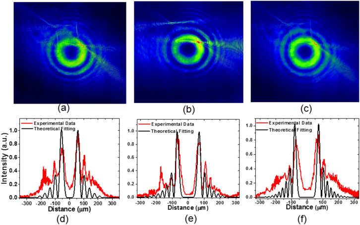
The laser patterns with Laguerre-Gaussian (LG0,l) modes with  = 0, 1, and 2 and unknown chirality were obtained by tuning the pump power of the laser diode27. The laser wavelength of 1.08 μm corresponded to a SP vortex wavelength of 1.06 μm as shown above. Focusing the laser beam on the surfaces of the PVLs as shown in Fig. 1, the SP vortices can be acquired. The patterns of SP vortices obtained with LG00 mode and right-handed rotated PVLs with the geometric topological charge m of −4, −7 and −10 are shown in Fig. 2 (a), (b) and (c). The intensity distribution of cross sections (red line) through the centers of obtained SP patterns are presented in Fig. 2 (d), (e) and (f). The theoretical intensity distribution equals to
  defined in eq. 2 shown in the Discussion part and is also shown in (d), (e) and (f) (black line) of Fig. 2 with order and topological charge of n = −4, −7 and −10. Since the peaks near the centers are much stronger than the outside ones26 and the relative position of peaks is determined by the orders of Bessel and Laguerre-Gaussian functions, we can find that in these figures, the relative position of experimental and theoretical peaks near the centers agrees well in principle, and by which we can determine the order of the Bessel functions and the orbital angular momentum per photon of SP vortices. The discrepancies may be generated by the imperfection of the PVLs, the dispersion of the focal lens and the sensitivity of the CCD.
Figure 1. Experimental configuration of generated SP vortices.
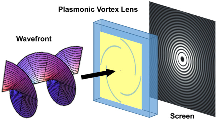
Light beams with the helical wavefront were focused on the surfaces of PVLs. The generated patterns were recorded with a CCD which was placed in a plane immediately behind the plane of the vortex lens as close as possible (z ≈ 0).
Figure 2. Experimental patterns and theoretical analysis of the SP vortices.
(a)–(c) Experimental patterns of SP vortices using a linearly polarized LG00 mode and PVL with m = −4, −7 and −10, respectively. (d)–(f) Experimental data (red lines) of the intensity distribution through the centers of obtained SP vortex patterns corresponding the patterns (a)–(c), respectively, and the theoretical fitting (black lines) of experimental data (red lines) with respective  functions shown in eq.(2) with n = −4, −7 and −10 and the adjusted size of the pattern.
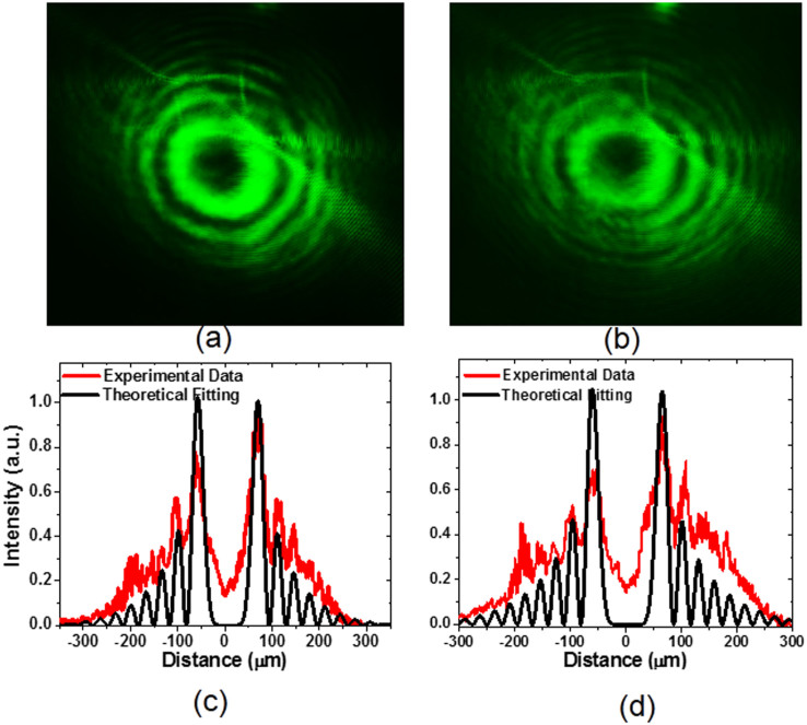
Increasing the pump power of the laser diode, light beams with LG0,l ( = 1 and 2) modes were achieved due to the increased nonlinearity including thermal focusing and Kerr effect in the gain medium which decreased the oscillating mode size in the cavity26. We found that compared to those shown in Fig. 2, the topological charges n of obtained SPPs increased by 1 or 2 depending on the topological charge
  of incident light beams. As representative results, the patterns with
  = 1 and 2, and m = −4 are shown in (a) and (b) of Fig. 3. The achieved experimental patterns and theoretical analysis of SP vortices with
  = 1 and 2, and n = −7 can be found in Supplementary Information. The intensity distribution of cross sections (red line) through the center is presented in the in (c) and (d) of this figure with topological charges of −5 and −6. From this figure, the total angular momentum per photon of SP vortices is
  . The results above also indicate that the chirality of the incident LG0,l modes is the same as the structure of the PVLs which is right-hand rotation and the signs of the topological charge of LG0,l modes should be minus (
 or −2). Therefore, the total angular momentum per photon of the SP vortices can be described with
  and the total angular momentum is conserved.
Figure 3. Experimental patterns and theoretical analysis of the SP vortices using a PVL with m = −4.
(a) and (b) Experimental patterns using linearly polarized LG0,−1 and LG0,−2 modes and a PVL with m = −4. (c) and (d) Experimental data (red lines) of the intensity distribution through the centers of obtained SP vortex patterns corresponding the patterns (a) and (b), respectively, and the theoretical fitting (black lines) of experimental data (red lines) with respective  functions shown in eq. (2) with n = −5 and −6 and the adjusted size of the pattern.
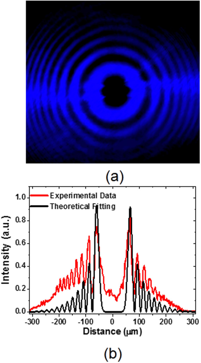
In order to investigate the angular momentum conservation deeply, the mirror symmetry operation for the PVLs was made by inverting the surface of PVLs. The structure of PVLs became left-handed rotation which is opposite to the incident light beams with LG0,l modes. In this condition, the sign of the PVLs' geometric topological charge m is positive, and the total topological charge is n = l + m. As representative results, the patterns with l = −1 and m = 10 are shown in Fig. 4 (a). The intensity distribution of cross sections (red line) through the center are presented in Fig. 4 (b) of this figure with topological charges of 9. It should be noted that the results show the PVLs can also be used as an optoelectronic device for determination of the topological charge of incident light beams and the total angular momentum is conserved during the process of SPP generation.
Figure 4. Experimental patterns and theoretical analysis of the SP vortices using a PVL with m = 10.
(a) Experimental patterns using linearly polarized LG0,−1 mode and a PVL with m = 10. (b) Experimental data (red lines) of the intensity distribution through the centers of obtained SP vortex patterns corresponding the patterns (a), and the theoretical fitting (black lines) of experimental data (red lines) with respective  functions shown in eq. (2) with n = 9 and the adjusted size of the pattern.
Considering the previous results with left- and right-hand polarized light beams with respective spin angular momentum of +1 and −1 and PVLs7, the results from this work indicate that similar to light waves in 2D spaces, the total angular momentum is conserved in all the entire process of SPP generation and the SP vortices should inherit the angular momentum of incident light beams and subwavelength PVLs. SP vortices have been identified to be capable to highly improve the resolution in fluorescence microscopy28. This work offers a possible choice for the high-resolution fluorescence microscopy. It can also be expected that this work would unveil the potential of SPPs in possible applications with tunable optical angular momentum per photon.
In conclusion, the optical angular momentum conservation rule is identified for optical vortex beams and PVLs with geometric topological charges. The generated angular momentum per photon of SP vortices is determined and can be tuned by the topological charge of incident vortex beams besides the geometric topological charges of PVLs. It can be expected that this work will unveil the potential of SPPs in the subwavelength region in some aspects.
Discussion
Only 20 years ago, the Laguerre-Gaussian (LGp,l) laser modes which are eigen modes of a laser cavity described in cylindrical coordinates were recognized to have orbital angular momentum per photon of  originating from their helical wavefront structure with phase dependence exp(ilφ)9. Recently, we reported the direct generation of LG0,l modes using a pump source with doughnut shaped intensity distribution to enforce the cylindrical symmetry of the generating system27. In the scheme, the orbital angular momentum per photons can be adjusted by the nonlinearity of the medium, e.g. thermal focal or Kerr effects. In the present study of SP vortex generation, the directly generated LG0l modes were used as incident light beam as shown in Fig. 1. A polarizer was inserted between the laser and the PVL to keep the linear polarization and zero spin angular momentum per photon of light9. The wavelength of the incident laser was centered at 1.08 μm.
The incident electric field Ein is the LGp,l laser mode with linear polarization along X direction  :
:
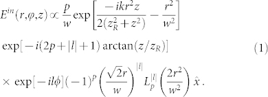 |
Here, p and l are the radial and azimuthal indexes of the mode respectively, k is the wavenumber of light in free space, w is the beam waist, zR is the Rayleigh rang of the mode, and  is the Laguerre polynomials. By theoretically analysis shown in Supplementary Information, the corresponding z-directional field electric field of the SP vortices is mathematically represented by the n-th order Bessel function Jn(x) and Laguerre-Gaussian function with a spiral phase profile given with a scalar equation by:
 |
With the angular momentum operator  and eqs. (3) and (4), it can be found that the LGp,l laser mode possesses the orbital angular momentum of
  per photon, and the generated SP vortices have orbital angular momentum of
  per photon which represents the twisted wavefront. Therefore, PVL can be considered possessing geometric topological charges of
  similar to the quasi-angular-momentum of quadratic nonlinear crystals having a geometrically twisted susceptibility pattern29,30. Because the Laguerre-Gaussian mode can keep its form unchanged during propagation and Bessel beam is diffraction-free and self-healing9,31,32, the generated SP vortex pattern should have some special propagating properties and the optical angular momentum
  per photon of SP vortices can be achieved by fitting observed patterns with the Bessel and Laguerre-Gaussian functions shown in eq. (2). The intensity of observed patterns is
  . Analogous to left- and right-handed circularly polarized light which carries respective spin angular momentum
  per photon14, geometric topological charges of the left-handed rotated PVLs are defined to be m, and those of the right-handed are −m.
Methods
Plasmonic vortex lenses (PVLs) design
The PVLs were designed to satisfy the following equation1:
 |
for 0 ≤ φ < 2π. Here, mod(mφ, 2π) represents the remainder of the division of mφ by 2π, ri is the inner radius defined as the distance from the center to the nearest point of the rim, the radius rm(φ) describes the rim of and interface between the gold film and quartz glass substrate with slits of 260 nm, λsp = 1.06 μm is the SP wavelength, and  is the polar unit vector. Since the transmission of the quartz glass substitute is high (about 97%) for the 1 μm light, the recoupling of SPPs and the SP vortex can be negligible. For
  the equation can be shown as:
 |
and the other divisions are the repeat operation on incident light of this division.
For air, the relative dielectric constant εair = 1, and for substrate, the relative dielectric constant εqua = 3.7. The relative dielectric of Au is calculated with a Drude model2:
 |
Here, ω is the frequency of the incident laser frequency, and ε∞, ωD and γD are the parameter set to fit empirical data for the real and imaginary part of the gold dielectric constant. For the wavelength at about 1 μm, the parameters are chosen as ε∞ = 11.4577, ωD = 9.4027 eV and γD = 0.08314 eV. The calculated gold dielectric constant at the wavelength λin of 1.08 μm is εAu = −55.2 + i4.8. Using the solved Maxwell's equations, the frequency-dependent SP vortices wavelength is3:
 |
The wavelength for a gold-air interface is calculated λSP = 0.98λin = 1.06 μm, at which condition, the momentum mismatching Δk = 0.
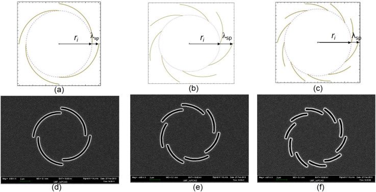
The detailed calculation for the design of PVLs and the designed PVLs with m = 4, 7 and 10 are available in Fig. 5. Analogous to the right- and left-handed rotating polarized light, the PVL slit patterns correspond to right-handed rotation looking from the bottom. The generated pattern of the SP vortices was directly recorded by a charge-coupled device (CCD).
Figure 5. Designed plasmonic vortex lenses.
(a), (b) and (c) The theoretical curves of the gold/quartz interface with m = 4, 7 and 10, respectively, calculated with eq.3. (d), (e) and (f) The designed PVLs with m = 4, 7 and 10, respectively.
Author Contributions
H.H. Yu and H.J. Zhang contributed equally to this work, conceived the experiments, performed the experiments, collected and analyzed the data, and wrote the paper; H.F. Yang and X.G. Xu prepared the Plasmonic vortex lenses; Y.C. Wang and S. Han performed the experiments; Z.P. Wang, J.Y. Wang and V. Petrov helped with the data analysis, theoretical calculation and paper writing.
Supplementary Material
Supplementary information
Acknowledgments
This work is supported by the National Natural Science Foundation of China (Nos. 51025210, 51102156, 51021062), Grant for State Key Program of China (No. 2010CB630702), the Program of Introducing Talents of Discipline to Universities in China (111 program).
References
- Barnes W. L., Dereux A. & Ebbesen T. W. Surface plasmon subwavelength optics. Nature 424, 824–830 (2003). [DOI] [PubMed] [Google Scholar]
- Ritchie R. H. Plasma Losses by Fast Electrons in Thin Films. Phys. Rev. 106, 874–881 (1957). [Google Scholar]
- Chang S. H., Gray S. K. & Schatz G. C. Surface plasmon generation and light transmission by isolated nanoholes and arrays of nanoholes in thin metal films. Opt. Express 13, 3150–3165 (2005). [DOI] [PubMed] [Google Scholar]
- Lalanne P., Hugonin J. P. & Rodier J. C. Theory of surface plasmon generation at nanoslit apertures. Phys. Rev. Lett. 95, 263902 (2005). [DOI] [PubMed] [Google Scholar]
- Lezec H. J. et al. Beaming light from a subwavelength aperture. Science 297, 820–822 (2002). [DOI] [PubMed] [Google Scholar]
- Lerman G. M., Yanai A. & Levy U. Demonstration of nanofocusing by the use of plasmonic lens Illuminated with radially polarized light. Nano Lett. 9, 2139–2143 (2009). [DOI] [PubMed] [Google Scholar]
- Kim H. et al. Synthesis and dynamic switching of surface plasmon vortices with plasmonic vortex lens. Nano Lett. 10, 529–536 (2010). [DOI] [PubMed] [Google Scholar]
- Shen Z. et al. Visualizing orbital angular momentum of plasmonic vortices. Opt. Lett. 37, 4627–4269 (2012). [DOI] [PubMed] [Google Scholar]
- Allen L., Padgett M. J. & Babiker M. The orbital angular momentum of light. Prog. Opt. 39, 291–372 (1999). [Google Scholar]
- Grier D. G. A revolution in optical manipulation. Nature 424, 810–816 (2003). [DOI] [PubMed] [Google Scholar]
- Padgett M. & Bowman R. Tweezers with a twist. Nature Photon. 5, 343–348 (2011). [Google Scholar]
- Foo G., Palacios D. M. & Swartzlander G. A. Jr Optical vortex coronagraph. Opt. Lett. 30, 3308–3310 (2005). [DOI] [PubMed] [Google Scholar]
- Furhapter S., Jesacher A., Bernet S. & Ritsch M. Spiral interferometry. Opt. Lett. 30, 1953–1955 (2005). [DOI] [PubMed] [Google Scholar]
- Molina T. G., Torres J. P. & Torner L. Twisted photons. Nature Phys. 3, 305–310 (2007). [Google Scholar]
- Scott T. F., Kowalski B. A., Sullivan A. C., Bowman C. N. & McLeod R. R. Two-color single-photon photoinitiation and photoinhibition for subdiffraction photolithography. Science 324, 913–917 (2009). [DOI] [PubMed] [Google Scholar]
- Wang J. et al. Terabit free-space data transmission employing orbital angular momentum multiplexing. Nature Photon. 6, 488–496 (2012). [Google Scholar]
- Zürch M., Kern C., Hansinger P., Dreischuh A. & Spielmann Ch. Strong-field physics with singular light beams. Nature Phys. 8, 743–746 (2012). [Google Scholar]
- Toyoda K. et al. Transfer of light helicity to nanostructures. Phys. Rev. Lett. 110, 143603 (2013). [DOI] [PubMed] [Google Scholar]
- Němec P. et al. Experimental observation of the optical spin transfer torque. Nature Phys. 8, 411–415 (2012). [Google Scholar]
- O'Neil A. T., MacVicar I., Allen L. & Padgett M. J. Intrinsic and extrinsic nature of the orbital angular momentum of a light beam. Phys. Rev. Lett. 88, 053601 (2002). [DOI] [PubMed] [Google Scholar]
- Marrucci L., Manzo C. & Paparo D. Optical spin-to-orbital angular momentum conversion in inhomogeneous anisotropic media. Phys. Rev. Lett. 96, 163905 (2006). [DOI] [PubMed] [Google Scholar]
- Dholakia K., Simpson N. B., Padgett M. J. & Allen L. Second-harmonic generation and the orbital angular momentum of light. Phys. Rev. A 54, 3742–3745 (1996). [DOI] [PubMed] [Google Scholar]
- Mair A., Vaziri A., Weihs G. & Zeilinger A. Entanglement of the orbital angular momentum states of photons. Nature 412, 313–316 (2001). [DOI] [PubMed] [Google Scholar]
- Tan P. S. et al. Phase singularity of surface plasmon polaritons generated by optical vortices. Opt. Lett. 36, 3287–3289 (2011). [DOI] [PubMed] [Google Scholar]
- Raether H. Surface plasmons on smooth and rough surfaces and on gratings. Springer Tracts Mod. Phys. 111, 1–133 (1988). [Google Scholar]
- Gorodetski Y., Drezet A., Genet C. & Ebbesen T. W. Generating far-field orbital angular momenta from near-field optical chirality. Phys. Rev. Lett. 110, 203906 (2013). [DOI] [PubMed] [Google Scholar]
- Zhao Y. G. et al. Direct generation of optical vortex pulses. Appl. Phys. Lett. 101, 031113 (2012). [Google Scholar]
- Tan P. S., Yuan X. C., Yuan G. H. & Wang Q. High-resolution wide-field standing-wave surface plasmon resonance fluorescence microscopy with optical vortices. Appl. Phys. Lett. 97, 241109 (2010). [Google Scholar]
- Bloch N. V. et al. Twisting light by nonlinear photonic crystals. Phys. Rev. Lett. 108, 233902 (2012). [DOI] [PubMed] [Google Scholar]
- Nikitin A. Yu., Zueco D., García-Vidal F. J. & Martín-Moreno L. Electromagnetic wave transmission through a small hole in a perfect electric conductor of finite thickness. Phys. Rev. B 78, 165429 (2008). [Google Scholar]
- Durnin J., Miceli J. J. Jr & Eberly J. H. Diffraction-free beams. Phys. Rev. Lett. 58, 1499–1501 (1987). [DOI] [PubMed] [Google Scholar]
- Arlt J. & Dholakia K. Generation of high-order Bessel beams by use of an axicon. Opt. Commun. 177, 297–301 (2000). [Google Scholar]
Associated Data
This section collects any data citations, data availability statements, or supplementary materials included in this article.
Supplementary Materials
Supplementary information


