Abstract
Purpose
The goal of this study was to develop a novel multi-point plastic scintillation detector (mPSD) capable of measuring the dose accurately at multiple positions simultaneously using a single optical transmission line.
Methods
A 2-point mPSD used a band-pass approach that included splitters, color filters, and an EMCCD camera. The 3-point mPSD was based on a new full-spectrum approach, in which a spectrograph was coupled to a CCD camera. Irradiations of the mPSDs and of an ion chamber were performed with a 6-MV photon beam at various depths and lateral positions in a water tank.
Results
For the 2-point mPSD, the average relative differences between mPSD and ion chamber measurements for the depth-dose were 2.4±1.6% and 1.3±0.8% for BCF-60 and BCF-12, respectively. For the 3-point mPSD, the average relative differences over all conditions were 2.3±1.1%, 1.6±0.4%, and 0.32±0.19% for BCF-60, BCF-12, and BCF-10, respectively.
Conclusions
This study demonstrates the practical feasibility of mPSDs. This type of detector could be very useful for pre-treatment quality assurance applications as well as an accurate tool for real-time in vivo dosimetry.
Keywords: scintillation dosimetry, multi-point, plastic scintillation detector, spectrometry, optical fiber
INTRODUCTION
As interest in plastic scintillation detectors (PSDs) in radiation therapy has grown over the past several years, these detectors have been applied to a variety of fields and have been subject to many practical evolutions. In 1992, Beddar et al. studied PSDs for application in external beam radiation therapy and showed many of their advantages, including their water-equivalence, small size, fast response and the independence of their energy and dose-rate responses (Beddar et al., 1992a, b). The PSD system was composed of a plastic scintillator, 2 silica fiber light guides, and 2 photomultiplier tubes. The use of the extra fiber and photomultiplier tube allowed the Cerenkov light to be subtracted from the signal of interest using the background fiber technique (Beddar et al., 1992c). In 1997, Aoyama et al. started using scintillating fibers, which are cylindrical scintillators with a cladding that enhances the internal total reflection of scintillation light and increases the amount of light coupled into the transmission optical fiber (Aoyama et al., 1997). To improve the water equivalence of the detector, Clift et al. replaced the silica optical guide with a plastic optical fiber in 2000 (Clift and Sutton, 2000).
Various approaches have been proposed to address the problem of Cerenkov light and obviate the need for the additional background fiber (and photodetector), since it was not reliable under high-dose gradients (Beierholm et al., 2008; Clift and Sutton, 2000; Fontbonne et al., 2002; Lambert et al., 2008). The technique introduced by Fontbonne et al. in 2002, in which the output from the detector is measured in 2 different optical windows, has been used widely and was shown to be very versatile (Archambault et al., 2006; Archambault et al., 2010; Beierholm et al., 2008; Fontbonne et al., 2002; Frelin et al., 2005; Guillot et al., 2011a; Guillot et al., 2011b; Lacroix et al., 2008; Therriault-Proulx et al., 2011a). The dose (d) is obtained using the following equation:
| (1) |
where fj is the calibration factor and mj the measured light intensity in spectral window j.
Red-green-blue photodiodes (Fontbonne et al., 2002; Therriault-Proulx et al., 2011b) and arrays of photomultiplier tubes (Beierholm et al., 2008) have been used to implement PSD setups with this technique, but it is more practical to use a CCD camera for applications involving a large number (e.g. > 50) of measurement points because such cameras can record the output from multiple detectors simultaneously. In 2008, Lacroix et al. (Lacroix et al., 2008) used a polychromatic CCD camera in the development of a 1-dimensional array of detectors for quality assurance applications. Then, in 2011, Guillot et al. developed a 2-dimensional array for quality assurance applications; the array was made of 781 PSDs and used monochrome cameras with optical filters, and its performance has been shown to be advantageous over other arrays of detectors (Guillot et al., 2011a). This photodetection setup was previously introduced by Archambault et al. for the development of an in vivo dosimetry application (Archambault et al., 2010). Guillot et al. also demonstrated that the choice of conditions for the calibration of the PSD was critical to the accuracy of the detector (Guillot et al., 2011b).
Even though PSDs are known to be the advantageous over other detectors, their use is hampered by the requirement for an optical fiber to be connected to each single point of measurement. Therefore, the development of multi-point applications is cumbersome and expensive. Moreover, in constrained space (e.g., in vivo measurements), PSD usage is limited to only a few points, typically between 1 and 5. Thus, we sought to develop a multi-point PSD (mPSD) capable of measuring the dose accurately at multiple positions simultaneously along a single optical transmission line. The challenge behind multi-point dosimetry using PSDs along a single transmission line is the superposition of a plurality of signals. The total light signal is composed of scintillation light from different scintillators as well as light produced within the optical guide (i.e., Cerenkov light). Innovative approaches for calibration and dose measurement were brought from theory (Archambault et al., 2012) to practice with the development of experimental techniques that made these approaches feasible, and performance of these novel mPSDs was validated for high-energy external beam irradiations. We developed 2- and 3-point detectors as examples to demonstrate the practical feasibility of using mPSDs for accurate dose measurements.
MATERIALS AND METHODS
We built an mPSD (see Fig. 1) consisting of 2 different scintillating elements (BCF-12 and BCF-60; Saint-Gobain Crystals, Hiram, OH, USA) that were each 2 mm long and 1 mm in diameter. The scintillating elements were separated from each other using a 28-mm-long, 1-mm-diameter piece of clear optical fiber (Eska GH-4001; Mitsubishi Rayon Co., Ltd., Tokyo, Japan). These scintillating elements were optically coupled to a single 20-m-long, 1-mm-diameter collection optical fiber (Eska GH-4001) to guide the light to the photodetector. The entire detector was made light-tight using a black polyethylene jacket whose outer diameter was 2.2 mm and a 3-mm-long, 1-mm-diameter polyethylene cap.
Figure 1.

Details of the 2-point plastic scintillation detector construction. The light-tight jacket covered the entire length of the detector; it is shown only partially covering the detector here so that the other elements are visible in the figure. L, length; d, diameter; Scint., scintillating element.
To assess the doses deposited within various scintillating volumes, we assumed that the total signal was a linear superposition of each light-emitting component (including the stem effect). The polychromatic Cerenkov removal technique introduced by Fontbonne et al. (Fontbonne et al., 2002) also relies on this assumption, although Fontbonne et al. assumed a superposition of only 2 spectra. Here, we applied our recently developed theoretical framework for mPSDs (Archambault et al., 2012).
In brief, to account for the additional scintillating elements, terms were added to equation 1. For the 2-point mPSD, the dose equation to a scintillating element is as follows:
| (2) |
where mj are the measurements made in the j optical spectral windows and fj,X are the associated calibration factors for each scintillating element. It is important to note that each scintillating element has its own set of calibration factors; that is, the calibration factors form a matrix, not a vector.
To implement this approach for multi-point dosimetry, the photodetection part of the mPSD requires a hyperspectral capability (i.e., a simultaneous collection of the information over a plurality of spectral bands). According to equation 2, with the 2-point mPSD, the signal must be resolved in a minimum of 3 spectral windows simultaneously. The photodetection setup used for the 2-point mPSD is presented in Fig. 2. The light was divided using a network of optical fiber splitters (DieMount GmbH, Wernigerode, Germany). The output from each branch (approximately 25% of the incoming light for this setup) was transmitted through a band-pass wavelength filter (Roscolux; Rosco, Stamford, CT), and each filter possessed its specific spectral transmission bands. The filters were selected to optimize the transmission of 1 light-emitting element—scintillation or stem effect—while minimizing the transmission of the other elements. The filters’ outputs were imaged on an EMCCD camera (Luca-R; Andor Technology, Belfast, N. Ireland) using a camera objective (Model 06B; CBC, Commack, NY). The background image was removed from each image and, following the application of switch-median filtering (Archambault et al., 2008), the intensity within each light spot was summed. The resulting light intensities are represented by mj in equation 2. After a proper calibration—to determine fj,X—the dose to each scintillating element could be calculated from a single image acquisition.
Figure 2.
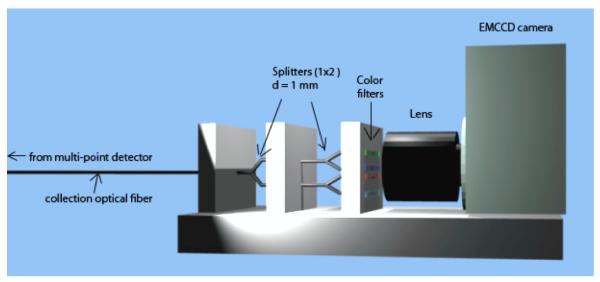
Photodetection part of the 2-point plastic scintillation detector. Light was separated by optical splitters and transmitted through different color filters (wavelength band-pass filters), and output was imaged on an EMCCD camera. d, diameter.
Calibration
To determine all 3 calibration factors, a minimum of 3 irradiation conditions had to be used. Generalizing from the recommendations of Guillot et al. (Guillot et al., 2011b) for a single-point detector, irradiation conditions were selected such that one maximized the Cerenkov emission while minimizing the scintillation contributions, the second deposited approximately the same dose to both scintillating elements, and the third deposited different doses to each scintillating element. Table I summarizes the irradiation conditions used for calibration.
Table I.
Irradiation conditions used to calibrate the 2-point plastic scintillation detector .
| Condition | Irradiation | Details |
|---|---|---|
| Cerenkov-optimized | 6 MeV electrons | Lead-shielded scintillators (d = 0); irradiation of optical fiber only |
| Similar dose to each scintillating element |
6-MV photon beam |
mPSD perpendicular to the beam; 10-cm × 10-cm field, SSD = 100 cm; depthBCF-60 = depthBCF-12 = 3 cm; dBCF-60 ≈ dBCF-12 ≠ 0 |
| Different dose to each scintillating element |
6-MV photon beam |
mPSD parallel to the beam; 10-cm × 10-cm field, SSD = 100 cm; depthBCF-60 = 5 cm; depthBCF-12 = 8 cm; dBCF-60 ≠ dBCF-12 ≠ 0 |
d, dose; SSD, source-to-surface distance.
Experiments
The 2-point mPSD was used to measure dose in a water tank (30 cm × 30 cm × 30 cm) with motorized-controlled displacements at various depths for a 6-MV photon beam (Varian Clinac 2100; Palo Alto, CA) with a 10-cm × 10-cm field size. Measurements were restricted to the 6 MV beam since no significant differences are expected with other energies from the linear accelerator (Beddar et al., 1992a, b). Irradiations of 50 MU at 600 MU/minute were performed. Measurements were done with the mPSD in both horizontal and vertical positions. The dose deposited by a 20-cm × 20-cm field at a 10-cm depth was also determined. Doses were calculated using equation 2 and compared with dose measurements obtained using an ion chamber (CC-04) under the same irradiation conditions.
A 3-point mPSD was also built. Its construction is presented in Fig. 3. It differed from the 2-point mPSD only by its additional scintillating element (BCF-10; Saint-Gobain Crystals, Hiram, OH), which was added between the 2 original scintillating elements (BCF-60 and BCF-12). In the 3-point mPSD, the scintillating elements were separated by 23-mm-long pieces of optical fiber (Eska GH-4001). The emission spectra of the 2 scintillating elements in the 2-point mPSD were quite different, which allowed us to select the band-pass filters accordingly and use equation 2. The addition of a third element made it more challenging to accomplish this task. The emission spectrum of the BCF-10 scintillating element overlapped substantially with the spectra of the BCF-12 and the stem effect (see Fig. 4), making it difficult to determine the best selection of band-pass filters to use. The decision was made to implement a different and innovative approach to measure the dose to each scintillating element accurately.
Figure 3.

Details of the 3-point plastic scintillation detector construction. The light-tight jacket covered the entire length of the detector; it is shown only partially covering the detector here so that the other elements are visible in the figure. L, length; d, diameter; Scint., scintillating element.
Figure 4.
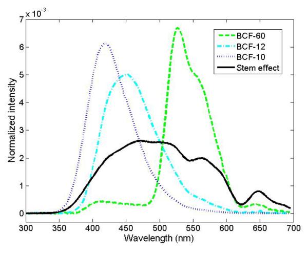
Spectra of the light-emitting component involved in this study. Each spectrum was obtained separately, but using the same probe (i.e. the 3-scintillator detector) during the calibration of the detector and normalized to the area under the curve.
A spectrograph (Shamrock; Andor Technology, Belfast, N. Ireland) coupled to a CCD camera (iDus; Andor Technologies, Belfast, N. Ireland) were used to measure the optical spectrum of the incoming light. With this setup, each component of the spectrum corresponds to 1 pixel on the CCD camera. The collection optical fiber (Eska GH-4001) was connected to the spectrograph through a SubMiniature version A (Thorlabs, Newton, NJ) connector.
In this dose measurement approach, as for the 2-point mPSD, it is assumed that the detected light is a linear superposition of the light coming from each light-emitting component. Therefore, the measured light spectrum (m) can be expressed as a linear superposition of each component normalized emission spectrum (ri) as follows:
| (3) |
where xi represents the intensity factor from each light-emitting component i. This can be represented by a highly over-determined set of linear equations when accounting for each individual wavelength:
| (4) |
| (5) |
The left pseudo-inverse technique (Archambault et al., 2012) is used to solve this system of equations for x (the array containing each of the contributions):
| (6) |
To calculate the dose to each scintillating element, one must perform at least 1 irradiation with a known dose (di,calib.) to each scintillating element. The intensity value is calculated for that situation (xi,calib.), and the dose for any condition can therefore be calculated using a simple cross-product ratio:
| (7) |
Calibration
A challenge of this technique is to obtain the individual (i.e. non-superposed) light emission spectrum from each light-emitting component as part of the calibration process. In this experiment, a superficial therapy unit (Philips RT-250; Philips Corp., Eindhoven, Holland) x-ray beam at 125 kVp was used to irradiate each scintillating element separately. A lead block was used to collimate (2 mm wide opening) the beam and prevent light production from other components. At 125 kVp, the production of Cerenkov light is impossible because the entire energy spectrum of the beam was below the Cerenkov production threshold of 178 keV in PMMA (the material composing the collection optical fiber). The stem effect spectrum was obtained by irradiating the collection optical fiber with a 6-MV photon beam (Varian Clinac 2100; Palo Alto, CA) prior to assembling the mPSD. All spectra were normalized to the area under the curve, as presented in Fig. 4.
To complete the calibration process, the mPSD was irradiated in a horizontal position with 100 MUs of a 6-MV photon beam. A 10-cm × 10-cm field size was used with the detector at a depth of 10 cm (source-to-surface distance = 100 cm) inside a water tank. The precise dose to each scintillating element was determined by measurements obtained using an ion chamber (CC-04). Once calibrated, the mPSD was able to calculate doses to the 3 scintillating elements from any single spectrum acquisition using equation 7.
Experiments
Using a 6-MV photon beam (Varian 2100 Clinac) with a source-to-surface distance of 100 cm, irradiations of 100 MU at 600 MU/minute were performed 3 times at each position for both the ion chamber and mPSD measurements. For each acquired spectrum, the background spectrum was subtracted. A moving median filter across the wavelengths was then applied to remove the outlying values caused by stray radiation. To increase the signal-to-noise ratio, the resulting spectrum was averaged over bins that were approximately 2.5 nm wide. The dose to each scintillating element was obtained using spectral decomposition, following the process explained earlier (equations 4-7).
Profile measurements were obtained for a 10-cm × 10-cm field at depths of 5 cm and 10 cm. The detector was then irradiated with a different field size (20 cm × 20 cm). A depth-dose measurement was also obtained for depths ranging from 1.5 cm to 20 cm. Finally, the profile of the beam was obtained with a 45-degree wedge (that is, with different doses to each scintillating element). Ion chamber measurements were obtained under the same irradiation conditions for comparison.
RESULTS
2-point mPSD
Depth-dose absolute measurements obtained with the mPSD horizontal and vertical are presented in Fig. 5. The average relative differences between the mPSD and the ion chamber measurements were 1.6 ± 1.4% for the horizontal configuration and 3.1 ± 1.8% for the vertical configuration for BCF-60, and 0.9 ± 0.6% for the horizontal configuration and 1.6 ± 1.0% for the vertical configuration for BCF-12. The average relative differences for measurement of a 20-cm × 20-cm field at 10-cm was of 6.8 ± 2.7% for BCF-60 and 2.2 ± 1.3% for BCF-12.
Figure 5.
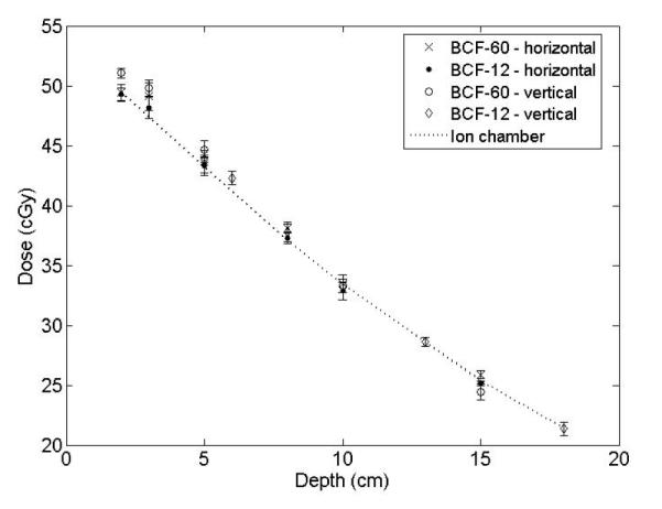
Depth-dose measurements obtained using the 2-point plastic scintillation detector and the ion chamber.
3-point mPSD
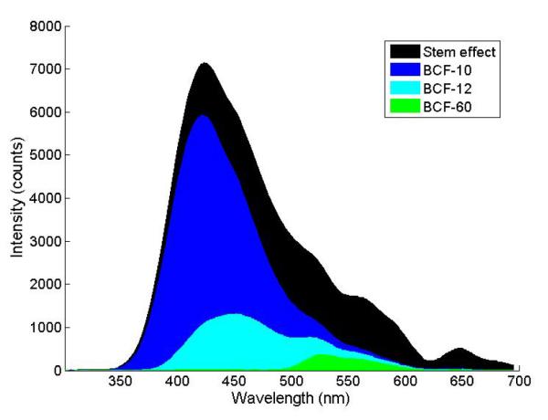
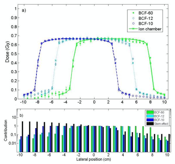
The approach proposed for the 3-point detector allows determining the contribution from each light-emitting component to the total signal, which was impossible with the other approach. This contribution varied as a function of the optical wavelength. Figure 6 shows an example of the contribution from each component for the known-dose irradiation condition used for calibration of the 3-point mPSD (10-cm × 10-cm field at a 10-cm depth). The dose profile measurements at a 10-cm depth are shown in Fig. 7a for both the mPSD and the ion chamber. The average contributions from each component are represented for various positions in Fig. 7b. The relative differences between the mPSD and the ion chamber measurements were calculated for this profile measurement as well as for all other irradiation conditions. Figure 8 shows the relative differences between depth-dose measurements obtained with the 3-point mPSD and those obtained with the ion chamber. A summary of relative differences between 3-point mPSD and ion chamber depth-dose and profile measurements is presented in Table II. Average relative differences between the mPSD and ion chamber measurements over the entire range of irradiation conditions were 2.3 ± 1.1%, 1.6 ± 0.4%, and 0.3 ± 0.2% for BCF-60, BCF-12, and BCF-10, respectively. Irradiation from the 20-cm × 20-cm field size at a 10-cm depth yielded an accuracy of 1.3 ± 4.4%, 1.6 ± 2.4, and 1.5 ± 0.3 for BCF-60, BCF-12, and BCF-10, respectively.
Figure 6.
Contribution of each light-emitting component to the total signal used for calibration of the 3-point plastic scintillation detector.
Figure 7.
a) Comparison of measurements obtained with each scintillation element and measurements obtained with an ion chamber for the calibration of the 3-point plastic scintillation detector (6-MV photon beam, 10-cm × 10-cm field, 10-cm depth). Error bars are 1 standard deviation, calculated from the 3 measurements. b) Relative contribution of each component to the total signal. Data were normalized to the average of data measured for calibration (lateral position = 0 cm).
Figure 8.
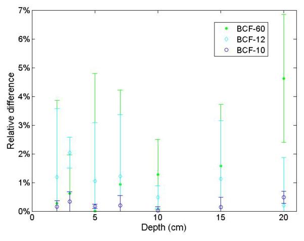
Relative differences between depth-dose measurements obtained from the 3-point plastic scintillation detector and from the ion chamber.
Table II.
Average ± standard deviation and maximum relative differences between measurements obtained using the 3-point plastic scintillation detector and those obtained using the ion chamber for 100 MUs irradiations.
| Relative difference (%) |
||
|---|---|---|
| Scintillating element | Average ± SD | Max. |
| BCF-60 | ||
| Profile (depth = 10 cm) | 2.1 ± 1.4 | 4.2 ± 0.7 |
| Profile (depth = 5 cm) | 2.0 ± 1.5 | 3.8 ± 0.5 |
| Depth-dose | 1.3 ± 1.4 | 4.6 ± 2.2 |
| 45-degree wedge | 3.9 ± 2.4 | 7.9 ± 3.7 |
| BCF-12 | ||
| Profile (depth = 10 cm) | 1.6 ± 1.1 | 3.9 ± 0.4 |
| Profile (depth = 5 cm) | 1.7 ± 1.3 | 2.6 ± 2.8 |
| Depth-dose | 1.1 ± 0.5 | 2.0 ± 0.5 |
| 45-degree wedge | 2.1 ± 1.1 | 4.1 ± 2.1 |
| BCF-10 | ||
| Profile (depth = 10 cm) | 0.3 ± 0.2 | 0.9 ± 0.4 |
| Profile (depth = 5 cm) | 0.2 ± 0.3 | 0.6 ± 0.2 |
| Depth-dose | 0.2 ± 0.1 | 0.5 ± 0.2 |
| 45-degree wedge | 0.6 ± 0.3 | 1.3 ± 0.6 |
DISCUSSION
Both mPSDs used in this study were shown to be in good agreement with the expected dose values as measured by the ion chamber under a variety of conditions. This demonstrates that mPSDs can be used to measure dose simultaneously at multiple points along a line using a single collection optical fiber. All processing to eliminate stray radiation and improve the signal-to-noise ratio was performed on a single image or spectrum, a technique that will be helpful in the development of real-time in vivo applications in which it would be impossible to do multiple irradiations (Archambault et al., 2008). The latter could be used for quality-assurance applications. The ability to process multiple images or spectra should lead to higher accuracy and precision.
The feasibility of measuring the dose with the mPSD in horizontal and vertical configurations was demonstrated using the 2-point mPSD. The detector appeared to show better accuracy while measuring doses in a horizontal setup than in a vertical setup, although the difference was not statistically significant (horizontal, 1.6 ± 1.4% for BCF-60 and 0.9 ± 0.6% for BCF-12; vertical, 3.1 ± 1.8% for BCF-60 and 1.6 ± 1.0% for BCF-12) if the standard deviation is considered. The increase in the transmission of Cerenkov light along the collection optical fiber in a vertical setup could explain the differing results between the 2 setups. Indeed, even if the production of Cerenkov was somewhat similar in both cases, a part of the optical fiber in the radiation field was at angle to the beam in the vertical setup leading to a notable increase in the amount of Cerenkov coupled in it (Beddar et al., 1992c).
For the 3-point mPSD measurements, the greatest differences compared with the ion chamber measurements were recorded in the penumbra of the beam (see Fig. 7a), which is the position with the highest dose gradients. As shown in Table II, measurements with the 45-degree wedge led to the largest differences and associated standard deviation, even though the average relative differences were less than 4%. Because the mPSD was under a higher dose gradient for the 45-degree wedge than for flat fields, most of the increase in uncertainty was likely due to the effect of positioning. Also, the presence of this physical wedge likely attenuated more of the signal, leading to a worse signal-to-noise ratio than for beams without any strongly attenuating medium in their path. In general, the technique used to account for the other light signals in the 3-point mPSD was efficient, even with varying contributions to the total signal from each light-emitting component (see Fig. 7b).
It was found that for both detectors and for all of the irradiation conditions, accuracy was highest for the scintillating element closest to the photodetection part of the mPSD. A weaker attenuation of the emitted scintillation light for these elements explains this finding; the light had to go through fewer interfaces and was less subject to optical loss. However, for the 3-point mPSD, the difference in accuracy between the 2 most distal scintillators appeared to be negligible, probably because of the superposition of 2 opposite effects: one scintillation element (BCF-12) was less subject to attenuation from multiple interfaces, but its emission spectrum (see BCF-12 in Fig. 3) overlapped more with the emission spectra of the other elements and was harder to accurately decouple from the total light compared with the BCF-60 scintillating element (see Fig. 3).
Because the various components of the mPSD we used for this study were coupled directly and the splicing and polishing of each component were done by hand, there are many ways the construction process could be improved to decrease the differences in light-intensity attenuation. The use of an index matching gel or glue (Ayotte et al., 2006), the addition of a reflector at the end of the detector (Letourneau et al., 1999), and the use of an industrial polishing machine to obtain a clean perpendicular cut at the ends of all scintillating and transmitting components are among possible improvements that would minimize the differences in attenuation between the scintillating elements. Changing the order of the scintillating elements so that it is based on scintillation efficiency and degree of similarity to the other components would also lead to more consistent accuracy between the scintillating elements. For the 3-point mPSD used in this study, swapping the BCF-12 and BCF-10 scintillating elements would probably lead to better overall accuracy of the mPSD. However, using scintillating elements with more distinct emission spectra would be even better. Optimization of the optical chain related to mPSDs is a goal for future work.
Even with more superposed signals coming from additional scintillating elements, the mPSDs presented in this study performed as well as or better than single-point detectors presented by others (Archambault et al., 2010; Lacroix et al., 2008; Lambert et al., 2008). Lacroix et al. reported a maximum relative difference to the expected dose of 1.6% for a 6-MV photon beam depth-dose measurement using an array of 29 single-element PSDs (Lacroix et al., 2008), and the PSD that Lambert et al. used, which had an air-core fiber, showed accuracy within 1.5% of the ion chamber measurements collected under the same irradiation conditions(Lambert et al., 2008). In our study, the proximal scintillating element of the 2-point mPSD achieved depth-dose measurements within an average of 1.6 ± 1.0% of the ion chamber measurements, and the 3-point mPSD in our study achieved depth-dose measurement accuracy within a maximum of 0.5 ± 0.2%. Archambault et al. (Archambault et al., 2010) reported that their PSDs agreed to within 0.3 ± 0.4% with the treatment planning for irradiation of a 200-cGy dose to the detector, which is in the same range as the reported accuracy for the BCF-10 scintillating element in our study (see Table I) for a maximum dose of 100 cGy.
In our study, we decided to use a different approach for the 3-point mPSD than we did for the 2-point mPSD. However, there is no theoretical limitation in using the approach shown for the 2-point mPSD for detectors with more than 2 scintillating elements. The maximum number of signals that can be resolved with this approach is defined only by the number of band-pass filters used. However, the selection of band-pass filters has to be made very cautiously to account for the plurality of scintillating elements and emission spectra. The use of optimal bandpass filters could lead to results as good as those obtained using the full-spectrum approach with a spectrometry setup (Archambault et al., 2012). Furthermore, for a defined set of scintillating spectra, the performance of the system is inherently related to the selected physical filters. The use of a spectrometry setup obviates the need for multiple physical band-pass filters. In fact, the band-pass theoretical approach could be implemented using the spectrometry setup used in this study: different regions of the spectrum would be integrated and act as the measurements Mi in equation 2. It is also important to note that for the splitter setup, the use of a CCD camera is not mandatory because an array of photodetectors, such as photodiodes, avalanche photodiodes, photomultiplier tubes, or silicon photomultipliers, could be used without any loss of generality. However, if a spectrometry setup is used, it is best to take advantage of the spectral information obtained by implementing the technique used here for the 3-point mPSD. Even with an additional scintillating component, this technique appeared to be more accurate and precise than the band-pass approach.
Using mPSDs to measure dose at multiple positions simultaneously, in real-time, and with a compact water-equivalent detector is a groundbreaking innovation that will facilitate the development of both in vivo applications during radiation therapy and quality assurance applications prior to the treatments. The development of mPSDs is particularly important when the space to insert detectors is limited, as is often the case for in vivo dosimetry inside catheters or spatially constrained orifices. Access to multiple points of measurement from a single detector makes dose measurement less invasive for patients. The development of arrays of detectors will also be eased by the use of mPSDs either by reducing the number of required fibers or allowing access to an additional dimension for the same number of collection fibers.
CONCLUSION
In this study, we showed that it is feasible to measure dose simultaneously at 2 and 3 points using scintillation detectors made of multiple scintillating elements coupled to a single collection optical fiber. This technique could be very useful for pre-treatment quality assurance as well as for the development of an efficient tool for real-time in vivo verification of dose delivery. There is no doubt that the advantages of this innovative technique will enhance the advantages of PSDs and may lead to their increased use for clinical applications. The system we used in this study was developed in-house, and further optimizations of the optical chain must be performed. Therefore, the accuracy of mPSDs should improve, increasing the possible number of dose measurement points per detector and/or decreasing the spatial resolution of the detectors.
ACKNOWLEDGMENTS
This work was supported in part by a Natural Sciences and Engineering Research Council Discovery grant (262105 and 385773) and a National Cancer Institute grant (1R01CA12019801A2). F.T.-P. was supported by the Natural Sciences and Engineering Research Council and Fonds Québécois de la Recherche sur la Nature et les Technologies.
Footnotes
US Patent pending.
REFERENCES
- Aoyama T, Koyama S, Tsuzaka M, Maekoshi H. A depth-dose measuring device using a multichannel scintillating fiber array for electron beam therapy. Med. Phys. 1997;24:1235–9. doi: 10.1118/1.598143. [DOI] [PubMed] [Google Scholar]
- Archambault L, Beddar AS, Gingras L, Roy R, Beaulieu L. Measurement accuracy and Cerenkov removal for high performance, high spatial resolution scintillation dosimetry. Med. Phys. 2006;33:128–35. doi: 10.1118/1.2138010. [DOI] [PubMed] [Google Scholar]
- Archambault L, Briere TM, Beddar S. Transient noise characterization and filtration in CCD cameras exposed to stray radiation from a medical linear accelerator. Med. Phys. 2008;35:4342–51. doi: 10.1118/1.2975147. [DOI] [PMC free article] [PubMed] [Google Scholar]
- Archambault L, Briere TM, Poenisch F, Beaulieu L, Kuban DA, Lee A, Beddar S. Toward a real-time in vivo dosimetry system using plastic scintillation detectors. Int J Rad. Onc. Biol. Phys. 2010;78:280–7. doi: 10.1016/j.ijrobp.2009.11.025. [DOI] [PMC free article] [PubMed] [Google Scholar]
- Archambault L, Therriault-Proulx F, Beddar S, Beaulieu L. A mathematical formalism for hyperspectral, multipoint plastic scintillation detectors. Phys. Med. Biol. 2012 doi: 10.1088/0031-9155/57/21/7133. in press. [DOI] [PubMed] [Google Scholar]
- Ayotte G, Archambault L, Gingras L, Lacroix F, Beddar S, Beaulieu L. Surface preparation and coupling in plastic scintillator dosimetry. Med. Phys. 2006;33:3519–25. doi: 10.1118/1.2256300. [DOI] [PubMed] [Google Scholar]
- Beddar AS, Mackie TR, Attix FH. Water-equivalent plastic scintillation detectors for high-energy beam dosimetry: I. Physical characteristics and theoretical considerations. Phys. Med. Biol. 1992a;37:1883–900. doi: 10.1088/0031-9155/37/10/006. [DOI] [PubMed] [Google Scholar]
- Beddar AS, Mackie TR, Attix FH. Water-equivalent plastic scintillation detectors for high-energy beam dosimetry: II. Properties and measurements. Phys. Med. Biol. 1992b;37:1901–13. doi: 10.1088/0031-9155/37/10/007. [DOI] [PubMed] [Google Scholar]
- Beddar AS, Mackie TR, Attix FH. Cerenkov light generated in optical fibres and other light pipes irradiated by electron beams. Phys. Med. Biol. 1992c;37:925–35. [Google Scholar]
- Beierholm AR, Andersen CE, Lindvold LR, Flemming K-K, Medin J. A comparison of BCF-12 organic scintillators and Al2O3:C crystals for real-time medical dosimetry. Radiation Measurements. 2008;43:898–903. [Google Scholar]
- Clift MA, Sutton RA. Dealing with Cerenkov radiation generated in organic scintillator dosimeters by bremsstrahlung beams. Physics in Medicine and. 2000;45:1165–82. doi: 10.1088/0031-9155/45/5/307. [DOI] [PubMed] [Google Scholar]
- Fontbonne JM, Iltis G, Ban G, Battala A, Venhes JC, Tillier J, Bellaize N, Lebrun C, Tamain B, Mercier K, Motin JC. Scintillating fiber dosimeter for radiation therapy accelerator. IEEE Trans. Nucl. Sci. 2002;49:2223–7. [Google Scholar]
- Frelin AM, Fontbonne JM, Ban G, Colin J, Labalme M, Battala A, Isambert A, Vela A, Leroux T. Spectral discrimination of Cerenkov radiation in scintillating dosimeters. Med. Phys. 2005;32:3000–6. doi: 10.1118/1.2008487. [DOI] [PubMed] [Google Scholar]
- Guillot M, Beaulieu L, Archambault L, Beddar S, Gingras L. A new water-equivalent 2D plastic scintillation detectors array for the dosimetry of megavoltage energy photon beams in radiation therapy. Med. Phys. 2011a;38:6763–74. doi: 10.1118/1.3664007. [DOI] [PubMed] [Google Scholar]
- Guillot M, Gingras L, Archambault L, Beddar S, Beaulieu L. Spectral method for the correction of the Cerenkov light effect in plastic scintillation detectors: A comparison study of calibration procedures and validation in Cerenkov light-dominated situations. Med. Phys. 2011b;38:2140–50. doi: 10.1118/1.3562896. [DOI] [PMC free article] [PubMed] [Google Scholar]
- Lacroix F, Archambault L, Gingras L, Guillot M, Beddar AS, Beaulieu L. Clinical prototype of a plastic water-equivalent scintillating fiber dosimeter array for QA applications. Med. Phys. 2008;35:3682–90. doi: 10.1118/1.2953564. [DOI] [PubMed] [Google Scholar]
- Lambert J, Yin Y, McKenzie DR, Law S, Suchowerska N. Cerenkov-free scintillation dosimetry in external beam radiotherapy with an air core light guide. Phys. Med. Biol. 2008;53:3071–80. doi: 10.1088/0031-9155/53/11/021. [DOI] [PubMed] [Google Scholar]
- Letourneau D, Pouliot J, Roy R. Miniature scintillating detector for small field radiation therapy. Med. Phys. 1999;26:2555–61. doi: 10.1118/1.598793. [DOI] [PubMed] [Google Scholar]
- Therriault-Proulx F, Briere TM, Mourtada F, Aubin S, Beddar S, Beaulieu L. A phantom study of an in vivo dosimetry system using plastic scintillation detectors for real-time verification of 192Ir HDR brachytherapy. Med. Phys. 2011a;38:2542–51. doi: 10.1118/1.3572229. [DOI] [PMC free article] [PubMed] [Google Scholar]
- Therriault-Proulx F, Beddar S, Briere TM, Archambault L, Beaulieu L. Technical Note: Removing the stem effect when performing Ir-192 HDR brachytherapy in vivo dosimetry using plastic scintillation detectors: A relevant and necessary step. Med. Phys. 2011b;38:2176–9. doi: 10.1118/1.3562902. [DOI] [PMC free article] [PubMed] [Google Scholar]


