Abstract
Bubble-based microfluidic devices have been proven to be useful for many biological and chemical studies. These bubble-based microdevices are particularly useful when operated at the trapped bubbles' resonance frequencies. In this work, we present an analytical expression that can be used to predict the resonant frequency of a bubble trapped over an arbitrary shape. Also, the effect of viscosity on the dispersion characteristics of trapped bubbles is determined. A good agreement between experimental data and theoretical results is observed for resonant frequency of bubbles trapped over different-sized rectangular-shaped structures, indicating that our expression can be valuable in determining optimized operational parameters for many bubble-based microfluidic devices. Furthermore, we provide a close estimate for the harmonics and a method to determine the dispersion characteristics of a bubble trapped over circular shapes. Finally, we present a new method to predict fluid properties in microfluidic devices and complement the explanation of acoustic microstreaming.
INTRODUCTION
Oscillating bubbles have been proven to be useful in controlling fluids and particles in many lab-on-a-chip applications.1 These bubble-based microfluidic systems were most effective when excited at the bubbles' resonance frequencies.2, 3 In their early-stage development, bubble-based microsystems comprised unbounded spherical bubbles in microchannels with random bubble sizes and locations. In recent years, researchers have expanded the functionalities of bubble-based microfluidic systems by trapping bubbles over solid structures.4, 5, 6, 7, 8, 9, 10 These trapped-bubbles can have prescribed sizes, locations, and shapes and thus offer superior performance. For example, microfluidic devices using bubbles trapped across horseshoe-shaped structures (HSS) have effectively demonstrated several distinct functionalities (such as mixing, gradient generation, and enzymatic reaction).7, 9, 10, 11, 12, 13
Although microfluidic devices using surface-trapped bubbles are effective, determining the bubbles' resonant frequencies remains a significant challenge. Experimentally, these are identified by sweeping the frequency and visually analyzing the bubbles' amplitude for maximum oscillation. This process can be time-consuming and prone to error. Though theoretical analysis for spherical bubbles exists, it is inapplicable for trapped-bubbles and hence do not guide the device design.13, 14, 15, 16, 17
Although analysis of the trapped-bubble, i.e., liquid-gas interface, has not been attempted, extensive analysis of unbounded liquid-gas and liquid-liquid interfaces has been performed.17, 18, 19, 20, 21, 22 In the case of bounded interfaces, formulation of a liquid-liquid interface has been developed.23, 24, 25 Attempts have also been made to analyze a cylindrical-shaped liquid-gas interface trapped over rectangular shapes.26, 27 Here, we extend the above approaches to determine the dispersion characteristics of the oscillation of trapped bubbles. We believe that with its advantages in accuracy and versatility, the theoretical analysis presented here could serve as a powerful tool for designing and optimizing many bubble-based microfluidic devices.
In this work, we theoretically investigate the resonance frequencies of liquid-gas interface trapped over horseshoe-shaped structures and compare with experimental observations. First, the capillary wave dispersion characteristics of the liquid-gas interface are derived from velocity potentials. Next, using Taylor-series expansion, the effect of viscosity on dispersion relations is determined. An extension of our theoretical approach for trapped-bubbles over arbitrary planar geometries is discussed. Later, the dispersion characteristics of liquid-gas interface, of commonly used liquids, are presented. Estimated resonant frequencies over rectangular horseshoe-shaped structures are compared with experimental data and explanations are provided. Following that, an inverse method to determine the physical properties of fluids is proposed. Finally, the microstreaming phenomenon is discussed based on the evaluated velocity potentials.
EXPERIMENTS
Polydimethylsiloxane (PDMS) microfluidic channels of dimensions 240 μm × 155 μm × 1000 μm were prepared using standard soft lithography and mold replica techniques. Fig. 1 shows a typical arrangement of the horseshoe-shaped structure in a microfluidic channel. Nine horseshoe-shaped structures, each with different widths (b) varying from 30 to 110 μm, were prepared. The height (a) and length (h) of the structures were fixed as 60 and 155 μm, respectively. When the channel is filled with fluid (e.g., de-ionised (DI) water), the fluid passes by the structure and induces a single bubble (liquid-gas interface) due to surface tension.6, 7, 8, 9 It is observed that with these dimensions of horseshoe structure an interface can be developed even at high flow rates of DI water. It is known that ambient gases diffuse in and out of the bubble through the PDMS28, 29 by a process known as rectified diffusion.30, 31 Since this microsystem is operated at low transducer voltages (8 Vpp), diffusion effects were not observed. Furthermore, these experiments, at room temperature and ambient pressure, were performed soon after the bubbles were trapped. Hence, in this preliminary study, the diffusion effects were not considered.
Figure 1.
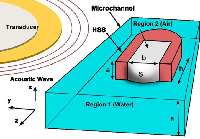
Schematic of a microchannel with a HSS in the center. Region 1, external to the HSS, is filled by a liquid (e.g., water) and region 2, inside the HSS, is occupied by air. The dimensions of the HSS (a, b, and h) and the amplitude of the water-air interface (S) are labeled in the figure. A piezoelectric transducer is used for acoustic activation of the bubble trapped at the HSS.
A piezoelectric transducer (Model No. 273-073, RadioShack), driven by a function generator (Hewlett Packard 8116A), was bonded next to the microfluidic device on the same glass substrate using epoxy. Upon actuating the piezoelectric transducer, the liquid-gas interface, here water-air, is set into oscillation. These oscillations result in a strong recirculating flow pattern in the liquid closer to the interface. This phenomenon, known as acoustic streaming, is most efficient when the interface is excited at its resonance frequency. Identification of resonance of interface oscillation was made by visual observation via a fast microscope, SA4 fastcam, Photron. Experiments were performed with three sets of horseshoe-shaped structures of all sizes. For each set of experiments, nine horseshoe-shaped-structures, of the mentioned sizes, are used in micro-channels, and the corresponding resonant frequencies are determined. The resonance frequency of the interface was determined experimentally by sweeping the excitation frequency from 5 kHz to 100 kHz, at a driving voltage of 8 Vpp.
THEORY
For the purpose of analysis, the region outside the horseshoe-shaped structures, in front of the interface S(x,y,t), is referred as region 1 and the region inside the horseshoe structures as region 2 (Fig. 1). Region 1 is filled with a liquid and region 2 is occupied by ambient air. Although region 1 could be filled with several streams of liquid, in this first study, we focus on the case of region 1 being completely filled with only one liquid (e.g., water). At equilibrium, at the liquid-air interface, the surface-tension forces balance the difference of pressure from both regions. To avoid repetitive explanations and use of the word “liquid-gas interface” or “water-air interface” from now on, the word “interface” will refer to the “liquid-gas interface” trapped across the horseshoe structure.
Broadly, the interface oscillation is guided by acoustic force, gravity, and capillary waves.32 Bond number,19 the ratio of buoyancy forces and surface tension forces, was found to be of the order of 10−4 for the horseshoe-shaped structures employed. Hence, we neglected the effect of gravity on fluid motion. Based on experimental observations, the interface is considered to be a near-flat surface in shape. If we only consider acoustic waves while neglecting capillary waves, the horseshoe structure can be considered as a rigid cuboid with the interface as a flexible membrane.33, 34, 35 For such a case, the resonant frequencies are calculated to be in the MHz range,36 while it is observed experimentally that resonant frequencies are in kHz range. This confirms the dominance of capillary force over acoustic force on the interface in the frequency range that we employ (5–100 kHz). Thus, the behavior of this bubble-based system is studied for only capillary wave forces. We assume the liquid to be inviscid;21 therefore, the pressure and velocity distribution in the system can be characterized by velocity potentials.15, 19, 20, 21 Let and denote the velocity potentials18, 19, 33 of regions 1 and 2, respectively; vz is the velocity of the interface in z direction; η is the viscosity of the liquid in region 1; is the interface amplitude; σ is surface tension of the interface; are the density of fluids in regions 1 and 2, respectively; and a, b, and h are the dimensions of horseshoe structure. For a small perturbation in the interface shape, we analyze the system to determine the dispersion relation and resonant frequencies. Since the interface oscillates in the z direction, the motion of the gas in region 2 is primarily normal to the interface; i.e., the velocity components of the gas normal to the walls of the horseshoe-shaped structure in the x, y directions, and are given by
| (1) |
| (2) |
where Eq. 2 is obtained from Eq. 1 using the definition of velocity potential. Let denotes the root-mean squared value of F(x,y) over the space variables x, y. The mean velocity of the interface at the open face of the horseshoe structure (z = 0) must be the same as that of the air velocity in region 2, given by
| (3) |
Experimentally, it is observed that the interface is pinned at the edges of the horseshoe structure's open face leading to the following boundary conditions for
| (4) |
Before the activation of the piezoelectric transducer, the interface is observed to be nearly flat, so
| (5) |
To be physically consistent, the velocity of the fluid away from the interface must diminish to zero. Hence, an exponential decay in the velocity profile as shown in Eq. 6 is considered. To satisfy Eqs. 1, 2, 3, 4, 5 and the expected exponential decay along the z-direction, the velocity potentials and interface amplitude will have the following form:
| (6) |
| (7) |
where is the wavenumber in the z-direction in region 2, is the amplitude of interface oscillation, are the wavenumbers along x, y directions, respectively, and m and n are the mode numbers along the cross-section dimensions, x and y. For liquid motion in region 1, described by the velocity potential, wavenumbers in directions parallel to interface, kx, ky, remain unchanged for a shear-free interface. Equating the velocity of the interface with velocity of fluid in region 1 at z = 0, the boundary condition given by
| (8) |
is imposed. Also, the incompressibility condition for the liquid yields
| (9) |
which shows that ψ satisfies the Laplace equation. On solving Eqs. 7, 8, 9, we obtain the velocity potential
| (10) |
Here, denotes the wavenumber in region 1 in the z direction. The relation between the wavenumbers, ,, can be determined from the continuity condition in the z direction37 across the interface given by
| (11) |
where Z1 and Z2 are the acoustic impedances and and are the speeds of sound for the fluids in regions 1 and 2, respectively. For a two-dimensional near-flat interface, the radius of curvature (R) can be approximated38
| (12) |
For the typical size of the horseshoe-shaped structures employed here (60 μm × 70 μm × 100 μm), it is experimentally observed that the amplitude of interface oscillation, 5–8 μm, is much smaller than the depth (h), 100 μm. In these cases, the variations in pressure can be written in terms of the average displacements or velocities similarly to the case of a kettledrum.37 Hence, the pressure variations are quantified by their root mean-squared spatial average over the interface area. For a small perturbation of the interface, the variations in pressure across the interface are balanced by the surface-tension forces18 as represented by
| (13) |
Here, at denotes the velocity at the interface. The first two terms in Eq. 13 denote the backpressure induced by the fluids in regions 2 and 1, respectively, due to the interface oscillations while the third term gives the effect of viscosity. In order to determine the minor effects of viscosity on interface behavior, we perform a perturbation analysis of frequency similar to established methods.17, 20, 22, 33, 35 Hence, the temporal damping constant and undamped resonant frequency ( are related to the complex angular resonant frequency by
| (14) |
Using Eqs. 6, 7, 10, and 13 in Eq. 14, the angular resonant frequencies are given by
| (15) |
where is the effective wavenumber and is the effective density. Thus, the resonant frequencies () of the interface are
| (16) |
The spatial damping is related to the complex wavenumber form as follows:17, 20, 22, 32, 35
| (17) |
The effect of viscosity on the system is determined in terms of the spatial and temporal damping constant. For the wavenumber , using a Taylor series expansion with respect to ω and retaining only the first-order term, the relation between spatial damping constant ( and temporal damping constant can be expressed as17, 34
| (18) |
Although experiments are conducted employing a rectangular horseshoe structure to obtain closed-form results, we extend the theory to derive the resonance characteristics of an interface trapped across a different, but simple, geometry−cylinder. Here, the interface is assumed to be pinned over a circular-cylindrical horseshoe-shaped structure of circular cross-section radius c. For a cylindrical coordinate system, the velocity potentials for the gas inside the horseshoe structure, ; the liquid outside the horseshoe structure, 39 and the interface amplitude, are given as
| (19) |
| (20) |
and
| (21) |
respectively. For the case of an interface pinned to the boundary, the boundary conditions are
| (22) |
Here, denotes the Bessel function of order v, is the amplitude of the interface, and , are the wavenumbers in the radial and the angular direction, respectively. For an initial small curvature of the interface, the radius of curvature can be approximated as38
| (23) |
For a small perturbation of the interface, the variations in pressure across the interface are balanced with surface tension forces as
| (24) |
Substituting Eqs. 19, 20, 21, 22, 23 in Eq. 24, the resonant frequencies can be estimated numerically.
RESULTS AND DISCUSSION
Dispersion
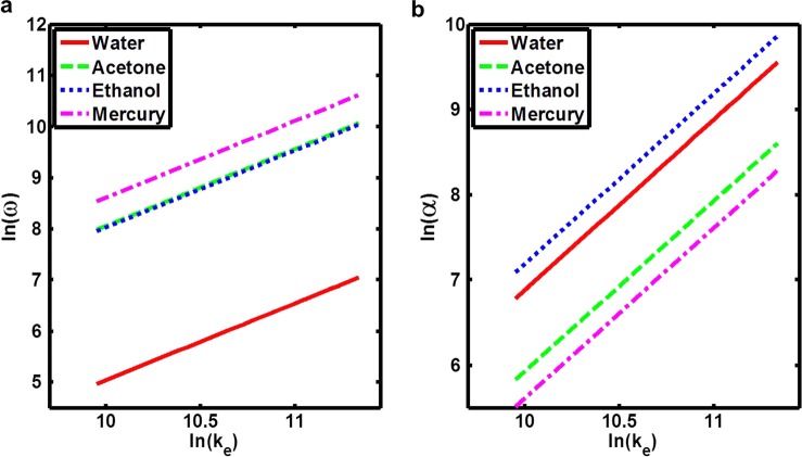
For the discussion and analysis presented in this sub-section, the properties of the fluids employed for simulations are shown in Table TABLE I. In separate simulations, water, acetone, ethanol, and mercury are assumed to occupy region 1 of the microchannel. Region 2 is always assumed to be occupied by ambient air. The range of frequencies applied in bubble-based microfluidic devices is 5–100 kHz. The corresponding dispersion relation for the capillary waves is determined using Eq. 15. The logarithmic dispersion relation and the temporal attenuation coefficient for these fluids are shown in Fig. 2. For the dispersion curves shown in Figs. 2a, 2b, the properties of fluids (acetone and ethanol) were close enough to display similar wave characteristics in the kHz range.
TABLE I.
Relevant physical properties of the various fluids used in the simulations.
| Density (kg/m3) | Bulk modulus (GPa) | Surface tension (N/m) | Viscosity in (m N/s m2) | |
|---|---|---|---|---|
| Air | 1.18 × 10⁻³ | 0.00 | … | … |
| Water | 1000.00 | 22.90 | 7.19 | 1.00 |
| Acetone | 791.00 | 0.92 | 23.70 | 0.31 |
| Ethanol | 789.50 | 0.90 | 22.27 | 1.07 |
| Mercury | 5430.00 | 28.50 | 487.00 | 1.53 |
Figure 2.
Simulated dispersion relations for the liquid-air interface. The gas considered in region 2 is air at 25 °C. ω is the angular frequency of the interface oscillation, α is the temporal damping constant of the wave, and is the effective wavenumber.
Resonant frequencies and harmonics
For an interface bounded by water in region 1 and air in region 2 over a rectangular horseshoe structure of cross-sectional dimensions: 60 μm × 65 μm, the resonant frequencies for different oscillation modes (harmonics) are estimated using the real part of Eq. 16. A plot is shown in Fig. 3a. Different mode shapes are shown in Fig. 3b where the numbers indicate the mode number.
Figure 3.
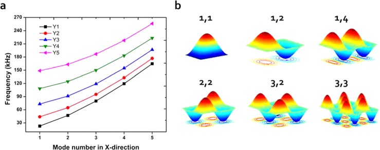
Simulated resonant frequencies for various oscillation modes of the rectangular-shaped interface. The vertical axis indicates the resonant frequencies for different mode numbers of the rectangular water-air interface. Y1, Y2, Y3, Y4, and Y5 denote the 1st, 2nd, 3rd, 4th, and 5th mode number of the interface in y-direction.
Comparison with experiments
Nine different sized horseshoe-shaped structures were fabricated, where one cross-section dimension (a) was kept constant at 60 μm and the other dimension (b) is varied from 30 to 110 μm. Experiments were performed following the procedure mentioned in Sec. 2. A comparison of the first resonant frequencies (f11) from theory and experiments for different cross section width (b) is shown in Fig. 4. Errors, represented as lines in Fig. 4, are determined by performing the experiments on three different sets of horseshoe-shaped structures. For each set of experiments, a new set comprising nine horseshoe-shaped-structures of the mentioned sizes is used in micro-channels. A slight deviation is observed between experimental results and theoretical predictions. The reason for this can be explained as follows: As the aspect ratio (b/a) deviates from unity, the amplitude of the capillary waves increases and the curvature becomes larger, thus, violating the assumptions employed to calculate the radius of curvature.
Figure 4.
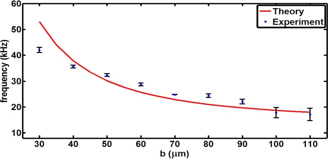
Comparison of experimentally determined resonant frequencies with theory for different cross-section dimension (b) of the horseshoe-shaped structure. The fixed dimension (a) is 60 μm. In these experiments, region 1 is filled by water and region 2 by air.
Estimation of fluid properties: Surface tension and viscosity
From the analytical expression for resonant frequencies, the fluid properties, surface tension, and viscosity can be determined from Eq. 16. In experiments, using a function generator, the frequencies are swept from lowest (∼5 kHz) to highest (∼100 kHz), and the amplitude of interface is determined by the high-speed camera. Experimentally, the frequencies that cause a local maximum in amplitude are considered as resonant frequencies. Based on similar analysis performed elsewhere,22 the surface tension of the liquid for different gases inside the horseshoe structure can be determined using
| (25) |
For fluids with unknown viscosities, the microsystem can be triggered at a known resonant frequency (of the interface) and turned off. The decay in amplitude of oscillation of the bubble, post trigger, can be measured and the viscosity can be estimated using Eq. 18. A plot for the decay in amplitude of the bubble is shown in Fig. 5.
Figure 5.
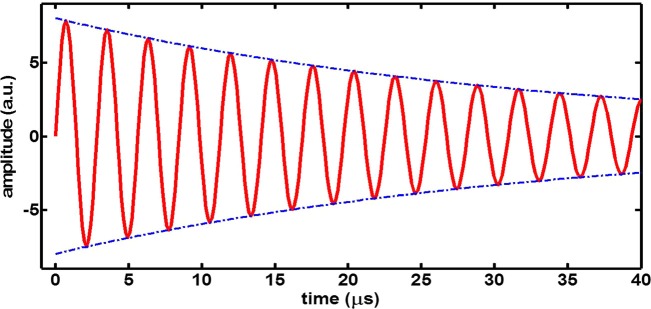
The simulated decay in bubble oscillation amplitude for a viscous medium at resonance frequency is shown in red. This simulated result is examined for the horseshoe structure designed in experiments described in sub-section (e). The blue line indicates the decrement in amplitude of bubble oscillation.
Microstreaming
The microstreaming phenomenon, which enhances mixing and facilitates generation of concentration gradients, is also observed near the interface (Fig. 6a). Early works have explained this phenomenon based on velocity potentials and stream functions.40, 41 More recently, a detailed analysis has been done for microchannels using perturbation theory accounting the effects of second-order velocity.42, 43, 44, 45 Using these theories40, 41, 42, 43, 44, 45 for the velocity potentials determined in our analysis, streaming velocities in the presence of a horseshoe structure-bound interface are determined. Fig. 6 demonstrates the development of streamlines in the presence of an acoustic field. Using the velocity potentials, given by Eqs. 6, 10, the streamlines near the interface in both regions 1 and 2 are plotted in Fig. 6b. Although streamlines in the air medium (region 1) are not visible through the microscope, these can be examined through simulations, shown in Fig. 6b. Fig. 6 indicates that our theory can qualitatively predict the flow patterns generated by an oscillating bubble trapped inside a horseshoe structure. The discrepancies between the experiments and simulations can be attributed to the fact that the horseshoe structure was assumed to be present in an infinite medium. Also, the width of the horseshoe structure boundaries was assumed to be infinitesimally thin. Future research will aim to address these issues and design more effective lab-on-a-chip systems by considering a time-domain three-dimensional simulation.
Figure 6.
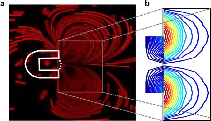
Streamlines illustrated in the presence of an acoustic field. (a) Experimentally observed acoustic streaming around the air-water interface. (b) Simulated streamlines based on derived velocity potentials. Lines shown represent streamlines at natural frequency (f11) near an air-water interface bound over the horseshoe structure of dimensions a and b: 65 and 70 μm, respectively. Box is shown only to correlate the experimental and simulated streamlines in water (region 2).
SUMMARY
In conclusion, the resonant frequencies for bubbles trapped in solid structures have been estimated theoretically. The theoretical results match well with experimental data. The dispersion relations for the trapped-bubbles have been derived. We have shown that by estimating the resonant frequencies from both experiments and theory, the physical properties of fluids, such as surface tension and viscosity, can be determined. We expect that the analysis presented here will be valuable in designing and fabricating more effective bubble-based microfluidic systems. Future work will focus on developing theoretical models accounting for higher curvatures of interface and the diffusion of air.
ACKNOWLEDGMENTS
This research was supported by National Institutes of Health (Director's New Innovator Award No. 1DP2OD007209-01), National Science Foundation, and the Penn State Center for Nanoscale Science (MRSEC) under Grant No. DMR-0820404. Components of this work were conducted at the Penn State node of the NSF-funded National Nanotechnology Infrastructure Network. The authors thank Daniel Ahmed, Yuliang Xie, Yanhui Zhao, and Joseph Rufo for their inputs.
References
- Hashmi A., Yu G., Collette M. R., Heiman G., and Xu J., Lab Chip 12, 4216 (2012). 10.1039/c2lc40424a [DOI] [PubMed] [Google Scholar]
- Tho P., Manasseh R., and Ooi A., J. Fluid Mech. 576, 191 (2007). 10.1017/S0022112006004393 [DOI] [Google Scholar]
- Rogers P. and Neild A., Lab Chip 11, 3710 (2011). 10.1039/c1lc20459a [DOI] [PubMed] [Google Scholar]
- Hashmi A. and Heiman G., Microfluid. Nanofluid. 14, 591 (2013). 10.1007/s10404-012-1077-5 [DOI] [Google Scholar]
- Liu R. H., Yang J., Pindera M. Z., Athavale M., and Grodzinski P., Lab Chip 2, 151 (2002). 10.1039/b201952c [DOI] [PubMed] [Google Scholar]
- Lapsley M. I., Ahmed D., Chindam C., Guo F., Lu M., Wang L., and Huang T. J., “Monitoring acoustic bubble oscillations with an optofluidic interferometer,” 16th International Conference on Miniaturized Systems for Chemistry and Life Sciences, Oct. 2012, pages 1906–1908. Available at http://www.rsc.org/images/loc/2012/pdf/W.7.164.pdf.
- Ahmed D., Mao X., Shi J., Juluri B. K., and Huang T. J., Lab Chip 9, 2738 (2009). 10.1039/b903687c [DOI] [PubMed] [Google Scholar]
- Tovar A. R., Patel M. V., and Lee A. P., Microfluid. Nanofluid. 10, 1269 (2011). 10.1007/s10404-010-0758-1 [DOI] [Google Scholar]
- Ahmed D., Mao X., Juluri B. K., and Huang T. J., Microfluid. Nanofluid. 7, 727 (2009). 10.1007/s10404-009-0444-3 [DOI] [Google Scholar]
- Ahmed D., Chan C. Y., Lin S.-C. S., Muddana H. S., Nama N., Benkovic S. J., and Huang T. J., Lab Chip 13, 328 (2013). 10.1039/c2lc40923b [DOI] [PMC free article] [PubMed] [Google Scholar]
- Glynne-Jones P. and Hill M., Lab Chip 13, 1003 (2013). 10.1039/c3lc41369a [DOI] [PubMed] [Google Scholar]
- Capretto L., Cheng W., Hill M., and Zhang X., Top. Curr. Chem. 304, 27 (2011). 10.1007/128_2011_150 [DOI] [PubMed] [Google Scholar]
- Xie Y., Ahmed D., Lapsley M. I., Lin S.-C. S., Nawaz A. A., Wang L., and Huang T. J., Anal. Chem. 84, 7495 (2012). 10.1021/ac301590y [DOI] [PMC free article] [PubMed] [Google Scholar]
- Strasberg M., J. Acoust. Soc. Am. 25, 536 (1953). 10.1121/1.1907076 [DOI] [Google Scholar]
- Leighton T. G., The Acoustic Bubble (Academic Press, 1992). [Google Scholar]
- Miller D. L. and Nyborg W. L., J. Acoust. Soc. Am. 73, 1537 (1983). 10.1121/1.389415 [DOI] [Google Scholar]
- Earnshaw J. C. and McLaughlin A. C., Proc. R. Soc. Edinburgh, Sect. A: Math. Phys. Sci. 433, 1889 (1991). Available at http://www.jstor.org/stable/51923. [Google Scholar]
- Landau L. D. and Lifshitz E. M., “ Course of theoretical physics,” in Fluid Mechanics (Pergamon, 1987). [Google Scholar]
- Lucassen J., Trans. Faraday Soc. 64, 2221 (1968). 10.1039/tf9686402221 [DOI] [Google Scholar]
- Reynders E. H. L. and Lucassen J., Adv. Colloid Interface Sci. 2, 347 (1970). 10.1016/0001-8686(70)80001-X [DOI] [Google Scholar]
- Debnath L., Nonlinear Water Waves (Academic Press, 1994). [Google Scholar]
- Behroozi F., Smith J., and Even W.. Am. J. Phys. 78, 1165 (2010). 10.1119/1.3467887 [DOI] [Google Scholar]
- Benjamin T. B. and Scott J. C.. J. Fluid Mech. 92, 241 (1979). 10.1017/S0022112079000616 [DOI] [Google Scholar]
- Benjamin T. B. and Eagle J. G., IMA J. Appl. Math. 35, 91 (1985). 10.1093/imamat/35.1.91 [DOI] [Google Scholar]
- Bruus H., Theoretical Microfluidics (Oxford University Press, 2008). [Google Scholar]
- Wang C., Rallabandi B., and Hilgenfeldt S., Phys. Fluids 25, 022002 (2013). 10.1063/1.4790803 [DOI] [Google Scholar]
- Xu J. and Attinger D.. Phys. Fluids 19, 108107 (2007). 10.1063/1.2790968 [DOI] [Google Scholar]
- Lu C., Sun Y., Harley S. J., and Glascoe E. A., in Proceedings of TOUGH Symposium, Lawrence Berkeley National Laboratory, Berkeley, California, September 17–19, 2012.
- Merkel T. C., Bondar V. I., Nagai K., Freeman B. D., and Pinnau I.. J. Polym. Sci., Part B: Polym. Phys. 38, 415 (2000). [DOI] [Google Scholar]
- Hsieh D.-Y. and Plesset M. S., J. Acoust. Soc. Am. 33, 206 (1961). 10.1121/1.1908621 [DOI] [Google Scholar]
- Eller A. and Flynn H. G., J. Acoust. Soc. Am. 37, 493 (1965). 10.1121/1.1909357 [DOI] [Google Scholar]
- Behroozi F., Eur. J. Phys. 25, 115 (2004). 10.1088/0143-0807/25/1/014 [DOI] [Google Scholar]
- Behroozi F. and Perkins A., Am. J. Phys. 74, 957 (2006). 10.1119/1.2215617 [DOI] [Google Scholar]
- Kolevzon V., Gerbeth G., and Pozdniakov G., Phys. Rev. E 55, 3134 (1999). 10.1103/PhysRevE.55.3134 [DOI] [Google Scholar]
- Lee K. Y., Chou T., Chung D. S., and Mazur E, J. Phys. Chem. 97, 12876 (1993). 10.1021/j100151a039 [DOI] [Google Scholar]
- Behroozi P., Cordray K., Griffin W., and Behroozi F., Am. J. Phys. 75, 407 (2007). 10.1119/1.2710482 [DOI] [Google Scholar]
- Kinsler L. E., Fray A. R., Coppens A. B., and Sanders J. V., Fundamentals of Acoustics (John Wiley and Sons, 2000). [Google Scholar]
- Seifert U., Adv. Phys. 46, 13 (1997). 10.1080/00018739700101488 [DOI] [Google Scholar]
- See general solutions to Laplacian equation in cylindrical coordinates. http://planetmath.org/laplaceequationincylindricalcoordinates works – last accessed on July 1, 2013.
- Lighthill J., J. Sound Vib. 61, 391 (1978). 10.1016/0022-460X(78)90388-7 [DOI] [Google Scholar]
- Rednikov A. Y. and Sadhal S. S., J. Fluid Mech. 667, 426 (2011). 10.1017/S0022112010004532 [DOI] [Google Scholar]
- Bruus H., Lab Chip 12, 20 (2012). 10.1039/c1lc20770a [DOI] [PubMed] [Google Scholar]
- Sadhal S. S., Lab Chip 12, 2292 (2012). 10.1039/c2lc40202e [DOI] [PubMed] [Google Scholar]
- Frampton K. D., Minor K., and Martin S., Appl. Acoust. 65, 1121 (2004). 10.1016/j.apacoust.2004.03.005 [DOI] [Google Scholar]
- Frampton K. D., Martin S. E., and Minor K., Appl. Acoust. 64, 681 (2003). 10.1016/S0003-682X(03)00005-7 [DOI] [Google Scholar]


