Abstract
Objective
This article describes the development and application of a novel multi-axis hand dynamometer for quantifying two-dimensional grip force magnitude and direction in the flexion-extension plane of the fingers.
Methods
A three-beam reconfigurable form dynamometer, containing two active beams for measuring orthogonal forces and moments regardless of point of force application, was designed, fabricated and tested. Maximum grip exertions were evaluated for sixteen subjects gripping cylindrical handles varying in diameter.
Results
Mean grip force magnitudes were 231 N (SD=67.7 N), 236 N (72.9 N), 208 N (72.5 N), and 158 N (45.7 N) for 3.81 cm, 5.08 cm, 6.35 cm and 7.62 cm diameter handles, respectively. Grip force direction rotated clockwise and the centre of pressure moved upward along the handle as handle diameter increased.
Conclusions
Given that the multi-axis dynamometer simultaneously measures planar grip force magnitude and direction, and centre of pressure along the handle, this novel sensor design provides more grip force characteristics than current sensor designs that would improve evaluation of grip characteristics and model-driven calculations of musculoskeletal forces from dynamometer data.
Keywords: 2D grip force, multi-axis grip dynamometer, handle design
1. Introduction
Frequent and intensive use of hand-operated instruments, such as knives, drills, or electronic devices, has been associated with increased risk for chronic musculoskeletal injuries (National Institute for Occupational Safety and Health, 1997; National Research Council, 2001). An essential aspect of controlling external hand loading is to understand the normal and shear (tangential) forces created between the fingers and the handle. If these relationships were better understood, one could better estimate internal biomechanical loading and design handles that minimize musculoskeletal forces.
The Jamar dynamometer (J. A. Preston Corporation, Clifton, NJ, USA) has been the standard instrument for quantifying grip strength for many years. Similar dynamometers have been used to characterize normative grip capacities for large and diverse groups of people (Blackwell, et al., 1999, Harkonen, et al., 1993, Mathiowetz et al., 1985). Although simple and easy to use, this type of dynamometer measures force in only one direction and has a handle form factor that is not representative of most handles encountered in everyday activities.
Improved grip dynamometers have been designed, but limitations related to the ease, detail and accuracy of grip force measurements and handle shape still exist (Amis, 1987, Edgren, Radwin, & Irwin, 2004, Fowler & Nicol, 1999, McGorry, 2001; Radwin, et al., 1991). Amis (1987) developed a dynamometer that can only measure force exerted by one finger at a time, replicate only a cylindrical handle shape, and is specific for a given hand size. The dynamometer described in Fowler et al. (1999) is also limited by an inability to measure force from multiple fingers simultaneously. Additionally, the sensor cannot divide the total finger force into the contribution from each finger segment. While Radwin et al. (1991) used a dynamometer to measure force vectors, their instrument cannot resolve the contribution from individual finger segments and it must be gripped twice (Edgren et al. 2004). Finally, McGorry (2001) developed a dynamometer that can compute grip force direction only in cases where very careful anthropometric measurements are made of the hand gripping the handle.
Instrumented gloves and force sensor mats applied to handles provide another method for measuring grip force (Hall, 1997, Kong & Freivalds, 2003, Kong, et al., 2004, Kong & Lowe, 2005, Radwin et al., 1992, Seo et al., 2007, Seo & Armstrong, 2008) but important limitations exist. While a glove eliminates the need for the handle to be instrumented, the presence of the glove and embedded sensors may affect grasp interaction between the hand and handle. Also, while force sensor mats enable measurement of force for each finger segment, each sensor requires calibration and can only measure normal force. Furthermore, force sensor mats may shift during use or may be difficult to appropriately contour to account for the geometry of an arbitrarily shaped object. In addition, glove- or handle-mounted sensors may not provide coverage for the entire finger or hand and therefore do not necessarily measure all of the grip force.
If external hand forces can be measured more accurately and easily such that one can more accurately estimate internal musculoskeletal loading with the aid of a biomechanical model, the ergonomic design of hand held tools and devices could be improved. To this end, a multi-axis grip dynamometer was developed. Our multi-axis dynamometer has the benefits of computing the location of finger force application and preventing thumb forces from confounding finger force, both of which can improve the accuracy of grip force measurements. Like the sensor presented in Radwin et al. (1991), different caps can be affixed to the dynamometer in order to mimic a wide variety of handle sizes and geometries. Additional benefits of our dynamometer include continuous measurement of grip force such that the rate of force development, fatigue and force variability can be easily determined. This dynamometer has been tested for repeatability and validity in both younger and older adults (Irwin and Sesto, 2010). The objectives of this paper are to describe the development and application of the multi-axis grip dynamometer.
2. Methods
2.1 Dynamometer Design
The strain gauge dynamometer described in Radwin et al. (1991), and as used in Edgren et al. (2004), was the basis for the design of the multi-axis dynamometer. The design objectives for the dynamometer required it to: 1) measure force up to a defined force limit, 2) have sufficient sensitivity to measure very small forces, 3) isolate the forces produced by fingers, 4) measure two independent force vectors per beam (including magnitude, angle and vertical centre of pressure) 5) make all the relevant measurements in one grip exertion, and 6) adapt to a wide range of handle sizes and handle geometries.
As described in Radwin et al. (1991), an array of strain gauges can be arranged at the base of a cantilever beam so that shear stresses are maximized and therefore the effects of bending stresses are theoretically completely removed. This is described mechanically as:
| (1) |
where
σ = bending stress in the beam
M = moment from applied load-
c = distance from neutral axis
I = moment of inertia
By mounting the strain gauges in pockets milled at the base, the distance from the neutral axis “c” approaches zero, bending stresses are minimized, and all the strain measured by the gauges is shear. Since the load application point does not alter the shear strain (see Equation 2), the shear strain measurement is the same regardless of point of load application along the cantilever such that:
| (2) |
where
τ = shear stress
V = shear force
Q = shear flow
T = thickness
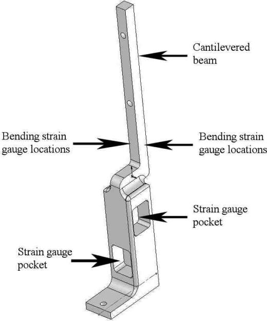
Depending on the curvature and shape of a handle, the point of force application along the finger should affect the force readings. The dynamometer was therefore designed to account for and quantify force vector angles. Compared to the Radwin et al. (1991) design, the new dynamometer beam includes an additional array of strain gauges in pockets orthogonal to the original set (Figure 1). The gages were mounted on the neutral axis of the pocket web with the grid lines oriented at 45°. These gauges allow force measurement in the perpendicular direction. Therefore, forces can be measured in both transverse directions so a more complete profile of the forces involved in gripping is obtained.
Figure 1.
Strain Gauge Locations.
In addition to the strain gauges mounted in the pockets, another two sets of bending strain gauges are mounted, without pockets, close to the base of the cantilever beam (Figure 1). These strain gauges detect bending moments. Along with the force measurements from the pocket gauges, which are unaffected by point of application, these gauges are used to determine the location that the resultant grip force is applied along the long axis of the beam (Equation 3). Recording the vertical position of the hand on the dynamometer allows estimation of the contribution of each finger to the overall grip force such that:
| (3) |
where
M = bending moment due to applied force
F = applied force
H = vertical distance from the bending moment strain gauges to the point of force application.
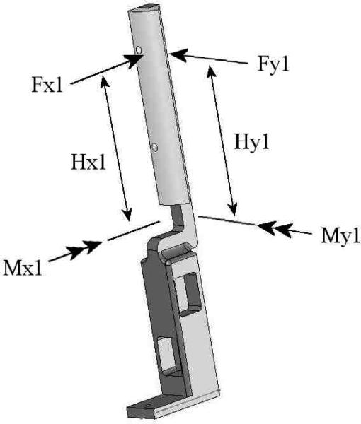
The strain gages were configured as a full Wheatstone bridge. Micro-Measurement (Raleigh, NC) strain gages packaged as rosette were used and were 350 Ω and compensated for 2024-T81 aluminum. Since the lower (instrumented) section of each beam is larger than the cantilevered section, the cantilevered segment is offset from the bottom segment to allow multiple beams to be mounted close together without interference. This is important for simulating small diameter handles. Figure 2 defines all of the variables that are measured using a single instrumented beam. The value for each variable is described in Table 1.
Figure 2.
Measurement Capabilities of One Instrumented Beam
Table 1.
Measurement of dynamometer variables.
| Variable | Measurement Method |
|---|---|
| F1x | Strain gauges mounted in pockets |
| F1y | |
| M1x | Strain gauges mounted on side of beam |
| M1y | |
| H1y | Calculated from M1x = H1y * F1y |
| H1x | Calculated from M1y = H1x * F1x |
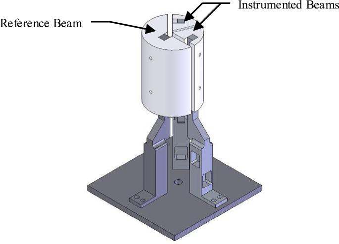
The three aluminium beams, with associated caps, are depicted in Figure 3. Two of the beams are instrumented as in Figure 1, and a third is a non-instrumented static reference beam. The instrumented beams are designed to be sensitive enough to detect forces in the range of 5 N to 250 N, yet be sufficiently stiff to resist deflections of more than a few millimetres when large forces are applied.
Figure 3.
Dynamometer with 7.62 cm Diameter Caps
The static reference beam serves two functions. First it is a stationary reference point from which the instrumented beam deflections, and therefore the forces applied, can be measured. Second it eliminates artefact forces produced by the thumb. An adjustable flange is connected to the thumb beam and its cap when gripping smaller diameter handles to ensure the thumb does not come into contact with the instrumented beams. When the flange is present, the thumb exerts force against the flange so it does not interfere with the measured finger forces.
2.2 Dynamometer Calibration
2.2.1 Procedure
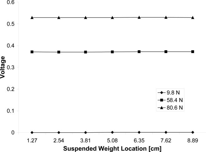
A calibration study of the multi-axis dynamometer was conducted to ensure force linearity, sensitivity, and accuracy in measuring multiple force vector information. Each beam was calibrated independently. The beams were oriented and rigidly clamped horizontally. Three known weights (9.8 N, 58.4 N, 80.6 N) were suspended at seven points along the long axis of the beam (1.27cm from the bending gauges to 8.89cm in 1.27cm increments) similar to Radwin et al. (1991) and the resulting output voltage was measured. The bending moment strain gauges, designed to help determine the location on the long axis where the resultant force acts, were calibrated in a similar fashion.
2.2.2 Data Analysis
Linear regression analyses were performed to investigate variation in output voltage due to suspended weight location for various applied loads. Linear regression analysis was also performed to examine output voltage due to applied bending moment.
2.3 Pilot Maximal Grip Force Study
2.3.1 Subjects
Sixteen subjects (eight male and eight female) participated in the maximum grip force study. Participants ranged in age from 22 to 41 years old. Average hand length was 18.77cm (SD=1.47 cm) and average hand breadth was 8.13cm (0.65 cm). Subjects were all right-hand dominant and were required to be injury-free in the right arm. Participants were interviewed and demographic data were collected. They were paid on an hourly basis and the experimental protocol was reviewed and approved by the University of Wisconsin Human Subjects Committee.
2.3.2 Procedure
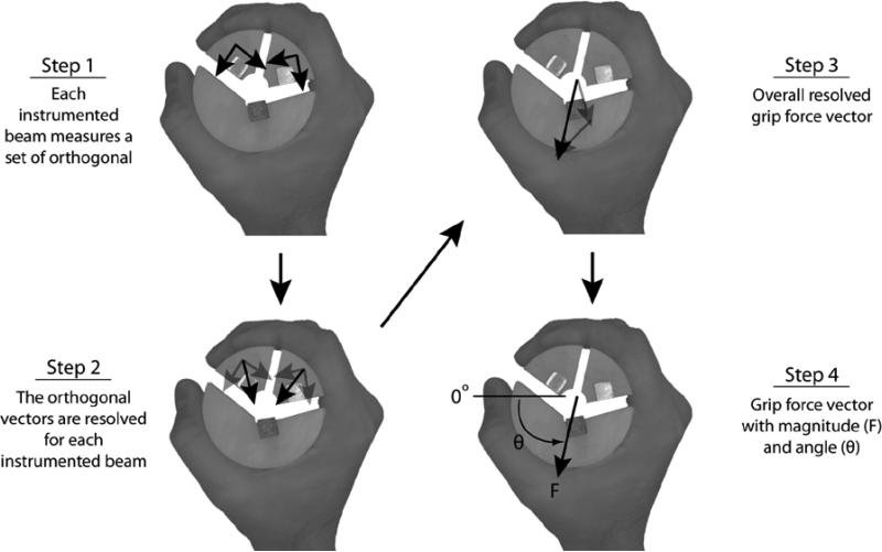
Grip force testing was conducted according to the procedures recommended by the American Society of Hand Therapists (Mathiowetz et al., 1985). Subjects were seated with elbow joint flexed at approximately 90° with the forearm and wrist in a neutral position. The MCP joints were aligned with the vertical gap between the proximal instrumented beam and the reference beam on the handle to ensure consistent hand placement for calculation of vertical centres of pressure (Fig. 4).
Figure 4. Hand Placement and Grip Force Measurement.
For each subject, the metacarpophalangeal joints were aligned with the vertical gap between the proximal instrumented beam and the reference beam on the handle to ensure consistent hand placement for calculation of vertical centres of pressure. Components of grip force are measured by proximal and distal instrumented beams (Step 1). Grip force is calculated after a series of vector additions (Steps 2-4). The origin of the force is located at the center of the instrumented (fingers) and reference (thumb) beams.
Subjects were instructed to squeeze the multi-axis dynamometer using maximum force for five seconds. The start and stop times were announced by the experimenter. The experimenter visually inspected the force data after each trial and selected the portion of the force output after the grip forces had stabilized. Two replications were performed at each of four handle sizes (handle 1 = 3.81 cm, handle 2 = 5.08 cm, handle 3 = 6.35 cm, and handle 4 = 7.62 cm) for a total of eight exertions. A three-minute rest was given between trials. The order in which the handles were presented was randomized.
2.3.3 Data Analysis
The resultant of the orthogonal force components measured by each instrumented beam was calculated. The grip force vector (F) magnitude and angle were then calculated by finding the vector sum of the resultant vectors of each instrumented beam (Fig. 4). The magnitude of F was used to determine which replication produced the maximum grip force. Only the data from the trial producing the maximum grip force was used in the analysis. For each beam, the centres of pressure were averaged.
Hand sizes were divided into the largest and smallest 50% based on median hand length (n=8 for both groups). The effects of handle diameter on grip force characteristics (magnitude, direction, centre of pressure) were evaluated using the analysis of variance and post-hoc Bonforoni pairwise analysis. In cases where a characteristic varied linearly with handle diameter, a regression analysis was performed.
3. Results
3.1 Dynamometer Design
As expected the output voltages from the pocket strain gauges were insensitive to the location of applied force along the length of the dynamometer (Fig. 5). Also, output voltage from bending moment strain gauges varied linearly with bending moment (R2=0.99).
Figure 5. Strain Gauges Characteristics.
The strain gauges mounted in the pockets produce the same force measurement regardless of point of force application.
3.2 Pilot Maximum Grip Force Study
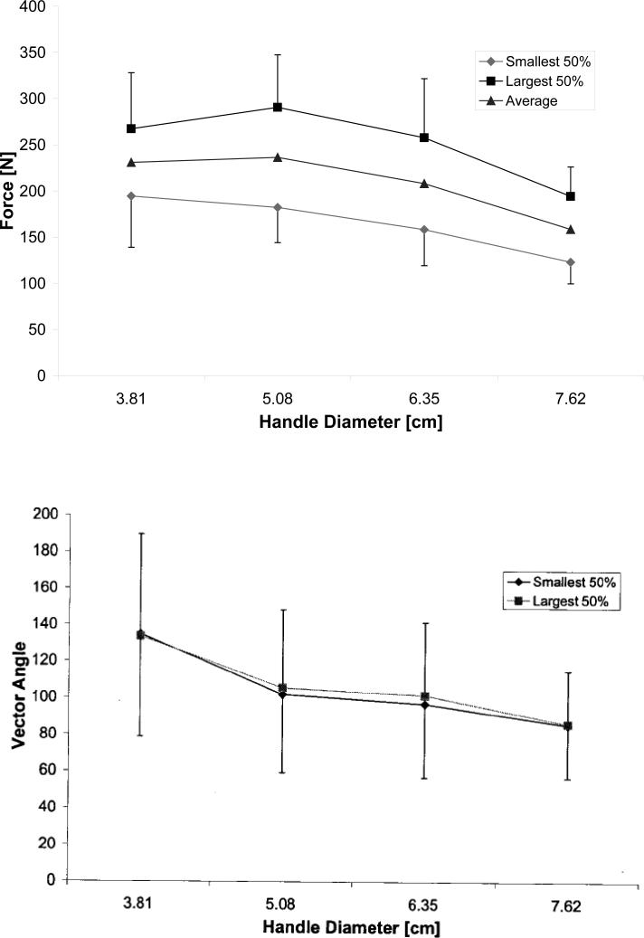
With few exceptions, grip force magnitude decreased and the grip force vector rotated clockwise, i.e., away from the thumb tip (see angle reference in Step 4, Fig. 4), with an increase in grip handle diameter. Specifically, mean grip force magnitudes were 231 N (SD=67.7 N), 236 N (72.9 N), 208 N (72.5 N), and 158 N (45.7 N) for the 3.81 cm, 5.08 cm, 6.35 cm, and 7.62 cm diameter handles, respectively. Significant differences existed for all comparisons except for handle 1 vs. both handles 2 and 3 (Fig. 6; F(3,13) = 27.286, p<0.01). Corresponding mean resultant grip force directions were 134 deg (13.6 deg), 107 deg (4.7 deg), 99.2 deg (8.2 deg), and 85.9 deg (7.9 deg). Significant differences existed for all comparisons except for handle 2 vs. handle 3 (F(3,13) = 27.286, p<0.01).
Figure 6. Grip Force Magnitude and Directional Variations with Handle Diameter.
Grip force magnitude decreased with increase in handle diameter (p<0.05) except when comparing force magnitudes for handle 1 and handle 2, and handle 1 and handle 3. Grip force vector direction decreased with increase in handle diameter (p<0.05) except when comparing force directions for handle 2 and handle 3. A decrease in force vector direction corresponds to clockwise rotation in force vector toward the thumb-tip (Fig. 5).
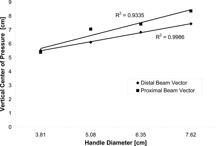
Vertical centres of pressure for the both the proximal (F(3,8)=5.0,p<0.05) and distal (F(3,13)=19.8,p<0.05) instrumented beams moved upward, in the direction of the radial side of the palm, with grip handle diameter (Fig. 7) and varied proportionally with handle diameter. The coefficient of determination for the variation in the proximal beam was 0.9335 and for the distal beam, 0.9986.
Figure 7. Vertical Centers of Pressure Variations with Handle Diameter.
Vertical center of pressure for each instrumented beam increased linearly with grip handle diameter.
4. Discussion
The goals of the study were to describe the development and application of a novel multi-axis dynamometer that measures 2D grip force in the flexion-extension plane of the fingers. The novel sensor design permitted continuous measurement of force that could account for contributions from different segments of the finger, provided separate segments were in contact with the proximal and distal instrumented beams. Force measurement was made independent of the point of force application while simultaneously measuring applied handle torque that permitted calculation of the centre of pressure of force. The handle was modifiable for different grip sizes and object geometries, and only needed to be gripped once to measure force and centre of pressure. We believe this multi-axis grip dynamometer, an extension of previous work from our laboratory (Radwin et al., 1991; Edgren et al., 2004), is the first of its kind and represents an enhancement to current grip force dynamometers in the field.
The calibration results demonstrate favourable characteristics of the dynamometer design. The calibration for the pocket strain gauges illustrate that the dynamometer could be gripped arbitrarily without impacting grip force measurement. This characteristic enables straightforward use of the dynamometer particularly in circumstances where subjects may tend to grip differently, e.g., for a range of different hand sizes, or following injury or disease. The calibration results for the bending moment strain gauges show well-defined, simple relationship between output voltage, applied force and location of applied force. It is no surprise that there was a linear relationship between output voltage in the bending moment strain gauges and the applied bending moment.
The novel design of the dynamometer facilitates estimation of the relative contributions of proximal and distal finger segments during gripping when such finger segments were aligned with each instrumented beam. Specifically, this was accomplished by integrating output of the strain gauges mounted on the surface of the beams that measured bending moments with output of the pocket-mounted strain gauges used to find the vertical centres of pressure (Equation 3). As previously shown, grip force vector direction decreased with increasing handle diameter, i.e., the force rotated clockwise toward the thumb for all subjects (Figs. 4, 6). This result agrees with that of a previous study (Edgren et al., 2004) in which two-dimensional grip force was measured in men and women with various sized hands using two grip exertions in orthogonal directions. We also showed that maximum grip force variation with handle diameter was shaped like an inverted-U, in which grip force initially increased and then decreased with increasing handle diameter (Fig. 6). This variation is consistent with previous studies in which other handle shapes were employed but only the normal force component of grip force was measured (Edgren et al., 2004; Fitzhugh, 1973; Oh and Radwin, 1993). This agreement suggests that grip force variation is robust to handle shape and that the normal force component predominates the other grip force components.
Grip force variation with handle diameter could be reflective of underlying changes in muscle architecture, e.g., muscle fiber lengths. Increases in handle diameter required finger joints to extend, which in turn produced elongations in the long finger flexor muscles, flexor digitorum superficialis (FDS) and flexor digitorum profundus (FDP). If the lengths of these muscles were such that they operated on the ascending limb of their force-length curves during grip of the smaller handles (diameters of 3.81 cm to 5.08 cm) and on the descending limb during grip of the larger handles (diameters of 5.08 cm to 7.62 cm), then well known changes in muscle force generation capacity due to muscle length variations (Aubert et al., 1951) could contribute to the measured grip force profile. Alterations in muscle moment arms while handling differ size handles could also contribute to grip force variation. Drawing conclusions from possible muscle moment arm changes, however, is less straightforward. Results from a recent cadaveric study (Franko et al., 2011) showed that changes in FDS and FDP moment arms due to finger extension are not monotonic; though, for most joints, the changes appear to be small over a large joint range (0 to 80 degrees of flexion). Perhaps, then, FDS and FDP muscle moment arm changes did not contribute much to variations in grip force with handle diameter. Finally, muscle activation could have influenced grip force as well. In the absence of direct muscle activity measurements or model predictions, it is difficult to speculate how it could have affected grip force measurement. Nevertheless, presumed changes in muscle fibre lengths remain a highly plausible contributing factor given that it was possible for changes in FDS and FDP muscle force generation capacity to mirror that of grip force variation with handle diameter. This is a topic for future research.
In this study, we also illustrated that the centre of pressure moved up the handle toward the index and middle fingers as handle diameter increased (Fig. 7). Such displacement of the vertical centre of pressure could be explained by reduced force contribution from the smaller fingers. Perhaps, as the handle diameter increased, the smaller fingers gradually extended to postures where it was increasingly difficult to exert force on the handle. As a result, the center of pressure moved up and away from the smaller fingers toward the larger fingers. The results from previous research intimates that the position of the vertical center of pressure remained constant. Amis (1987) reported that the contribution percentage of normal force for each finger was relatively consistent across handle diameters which would result in no change of the centre of pressure. It is possible that including shear force, as well as normal force, in the measurement of force vectors helps to explain differences in finger force contributions between studies. Radwin et al. (1992) demonstrated similar results to the current study with the index and middle fingers contributing more to the overall pinch force as load level increased. These findings may be useful in the design of hand-held products and equipment. For example, the centre of pressure data could be used to position triggers and buttons in the most beneficial places. It could also be used to design tapered handles which take advantage of the measured trend that certain fingers produce proportionately more force at certain handle diameters.
This multi-axis dynamometer also has numerous additional potential applications including use as a clinical evaluation instrument (Irwin and Sesto, 2010) as well as for ergonomic design. Clinically, researchers have been attempting to link grip strength to overall body strength and general health (Onder et al., 2005, Rantanen et al., 1999, Voorbij & Steenbekkers, 2001). In addition to simply measuring grip force, this dynamometer could be used to non-invasively evaluate injury, disease or age related deficits in maintenance and control of musculoskeletal structures.
Grip force measurements may also serve as direct input to the appropriate musculoskeletal model. Force magnitude and direction, and grasp contact point locations—which are unavailable with most grip dynamometers—are integral inputs for biomechanical models for calculation of musculoskeletal kinetics. Calculation of joint or musculotendon forces andstresses in the hand, that are influenced by grip force direction and location of vertical center of pressure, might lead to improved hand biomechanical models.
5. Conclusions
In this study, we described the development and application of a novel multi-axis hand dynamometer for quantifying grip force magnitude and direction in the flexion-extension plane of the fingers. This dynamometer was capable of measuring forces produced by different finger segments and prevents confounding influence from the thumb in a single exertion by the hand. Enhanced capabilities of this dynamometer could provide more accurate measurements of grip force that improve model-driven calculations of musculoskeletal kinetics which could, in turn, improve ergonomic design of devices that interface with the hand, e.g. multi-degree-of-freedom handles like joystick controllers or medical instruments. The dynamometer could also be potentially used as a tool to assist in evaluation of musculoskeletal injury. As stated earlier, we believe this multi-axis grip dynamometer is the first of its kind and represents an enhancement to current grip force dynamometers in the field.
Practitioner Summary.
The dynamometer was designed to isolate and describe force vectors produced by the finger segments. It may be particularly more suitable than current grip force dynamometers for improving model-based estimations of musculoskeletal forces and stresses that could ultimately improve ergonomic design of devices that interface with the hand.
Acknowledgments
The contents of this paper were developed under grant T32 AG000265 (Carnes) from the National Institute of Aging.
References
- Amis AA. Variation of finger forces in maximal isometric grasp tests on a range of cylinder diameters. Journal of Biomedical Engineering. 1987;9(4):313–320. doi: 10.1016/0141-5425(87)90079-3. [DOI] [PubMed] [Google Scholar]
- Aubert X, Roquet ML, Van der Elst J. The tension-length diagram of the frog's sartorius muscle. Arch. Intern. de Physiol. 1951;59:239–241. doi: 10.3109/13813455109145002. [DOI] [PubMed] [Google Scholar]
- Blackwell JR, Kornatz KW, Heath EM. Effect of grip span on maximal grip force and fatigue of flexor digitorum superficialis. Applied Ergonomics. 1999;30(5):401–405. doi: 10.1016/s0003-6870(98)00055-6. [DOI] [PubMed] [Google Scholar]
- Das B, Jongkol P, Ngui S. Snap-on-handles for a non-powered hacksaw: An ergonomics evaluation, redesign and testing. Ergonomics. 2005;48(1):78–97. doi: 10.1080/00140130410001686366. [DOI] [PubMed] [Google Scholar]
- Edgren CS, Radwin RG, Irwin CB. Grip force vectors for varying handle diameters and hand sizes. Human Factors. 2004;46(2):244–251. doi: 10.1518/hfes.46.2.244.37337. [DOI] [PubMed] [Google Scholar]
- Fitzhugh FE. Occupational Health and Safety Engineering Technical Report. Dept. of Industrial and Operations Engineering, The University of Michigan; 1973. Grip Strength Performance in Dynamic Gripping Tasks. [Google Scholar]
- Fowler NK, Nicol AC. A force transducer to measure individual finger loads during activities of daily living. Journal of Biomechanics. 1999;32(7):721–725. doi: 10.1016/s0021-9290(99)00054-8. [DOI] [PubMed] [Google Scholar]
- Franko OI. Moment arms of the human digital flexors. Journal of Biomechanics. 2011;44:1987–1990. doi: 10.1016/j.jbiomech.2011.04.025. [DOI] [PMC free article] [PubMed] [Google Scholar]
- Hall C. External pressure at the hand during object handling and work with tools. International Journal of Industrial Ergonomics. 1997;20(3):191–206. [Google Scholar]
- Harkonen R, Piirtomaa M, Alaranta H. Grip strength and hand position of the dynamometer in 204 finnish adults. Journal of Hand Surgery-British and European Volume. 1993;18B(1):129–132. doi: 10.1016/0266-7681(93)90212-x. [DOI] [PubMed] [Google Scholar]
- Irwin CB, Sesto ME. Reliability and validity of the MAP (Multi-Axis Profile) dynamometer with younger and older participants. Journal of Hand Therapy. 2010;23(3):281–288. doi: 10.1016/j.jht.2010.02.002. [DOI] [PMC free article] [PubMed] [Google Scholar]
- Irwin CB, Kage CC, Gruben KG, Sesto ME. Examination of older females’ grip characteristics.. Human Factors and Engineering Society 54th annual meeting; Submitted for publication. [Google Scholar]
- Irwin CB, Radwin RG. A new method for estimating hand internal loads from external measurements. Ergonomics. 2007;19:1–12. doi: 10.1080/00140130701526408. [DOI] [PubMed] [Google Scholar]
- Keir PJ, Mogk JPM. The development and validation of equations to predict grip force in the workplace: Contributions of muscle activity and posture. Ergonomics. 2005;48(10):1243–1259. doi: 10.1080/00140130500277591. [DOI] [PubMed] [Google Scholar]
- Kong YK, Freivalds A, Kim SE. Evaluation of handles in a maximum gripping task. Ergonomics. 2004;47(12):1350–1364. doi: 10.1080/00140130410001715697. [DOI] [PubMed] [Google Scholar]
- Kong YK, Freivalds A. Evaluation of meat-hook handle shapes. International Journal of Industrial Ergonomics. 2003;32(1):13–23. [Google Scholar]
- Kong YK, Lowe BD. Optimal cylindrical handle diameter for grip force tasks. International Journal of Industrial Ergonomics. 2005;35(6):495–507. [Google Scholar]
- Mathiowetz V, Kashman N, Volland G, Weber K, Dowe M, Rogers S. Grip and pinch strength - normative data for adults. Archives of Physical Medicine and Rehabilitation. 1985;66(2):69–74. [PubMed] [Google Scholar]
- McGorry RW. A system for the measurement of grip forces and applied moments during hand tool use. Applied Ergonomics. 2001;32(3):271–279. doi: 10.1016/s0003-6870(00)00062-4. [DOI] [PubMed] [Google Scholar]
- National Institute for Occupational Safety and Health Muscoloskeletal disorders and workplace factors. 1997. Chapter 5.
- National Research Council . Musculoskeletal disorders and the workplace. National Academy Press; 2001. [Google Scholar]
- Oh S, Radwin R. Pistol grip power tool handle and trigger size effects on grip exertions and operator preference. Human Factors. 1993;35(3):551–569. doi: 10.1177/001872089303500311. [DOI] [PubMed] [Google Scholar]
- Onder G, Penninx BWJH, Ferrucci L, Fried LP, Guralnik JM, Pahor M. Measures of physical performance and risk for progressive and catastrophic disability: Results from the women's health and aging study. Journals of Gerontology Series A-Biological Sciences and Medical Sciences. 2005;60(1):74–79. doi: 10.1093/gerona/60.1.74. [DOI] [PubMed] [Google Scholar]
- Radwin RG, Masters GP, Lupton FW. A linear force-summing hand dynamometer independent of point of application. Applied Ergonomics. 1991;22(5):339–345. doi: 10.1016/0003-6870(91)90393-v. [DOI] [PubMed] [Google Scholar]
- Radwin RG, Oh S, Jensen TR, Webster JG. External finger forces in submaximal static prehension. Ergonomics. 1992;35(3):275–288. doi: 10.1080/00140139208967813. [DOI] [PubMed] [Google Scholar]
- Rantanen T, Guralnik JM, Foley D, Masaki K, Leveille S, Curb JD, et al. Midlife hand grip strength as a predictor of old age disability. Jama-Journal of the American Medical Association. 1999;281(6):558–560. doi: 10.1001/jama.281.6.558. [DOI] [PubMed] [Google Scholar]
- Seo N, Armstrong T, Ashton-Miller J, Chaffin D. The effect of torque direction and cylindrical handle diameter on the coupling between the hand and a cylindrical handle. Journal of Biomechanics. 2007;40(14):3236–3243. doi: 10.1016/j.jbiomech.2007.04.023. [DOI] [PubMed] [Google Scholar]
- Seo N, Armstrong T. Investigation of grip force, normal force, contact area, hand size, and handle size for cylindrical handles. Human Factors. 2008;50(5):734–744. doi: 10.1518/001872008X354192. [DOI] [PMC free article] [PubMed] [Google Scholar]
- Voorbij AIM, Steenbekkers LPA. The composition of a graph on the decline of total body strength with age based on pushing, pulling, twisting and gripping force. Applied Ergonomics. 2001;32(3):287–292. doi: 10.1016/s0003-6870(00)00068-5. [DOI] [PubMed] [Google Scholar]
- Zhang YQ, Niu IB, Kelly-Hayes M, Chaisson CE, Aliabadi P, Felson DT. Prevalence of symptomatic hand osteoarthritis and its impact on functional status among the elderly - the framingham study. American Journal of Epidemiology. 2002;156(11):1021–1027. doi: 10.1093/aje/kwf141. [DOI] [PubMed] [Google Scholar]
- Zhang YQ, Niu JB, Kelly-Hayes M, Aliabadi P, Felson DT. Prevalence of symptomatic hand osteoarthritis and its impact on functional status: The framingham study. Arthritis and Rheumatism. 2001;44(9):S225–S225. [Google Scholar]


