Abstract
Polymer-based microneedles have drawn much attention in transdermal drug delivery resulting from their flexibility and biocompatibility. Traditional fabrication approaches are usually time-consuming and expensive. In this study, we developed a new double drawing lithography technology to make biocompatible SU-8 microneedles for transdermal drug delivery applications. These microneedles are strong enough to stand force from both vertical direction and planar direction during penetration. They can be used to penetrate into the skin easily and deliver drugs to the tissues under it. By controlling the delivery speed lower than 2 μl/min per single microneedle, the delivery rate can be as high as 71%.
Microelectromechanical systems (MEMS) technology has enabled wide range of biomedical devices applications, such as micropatterning of substrates and cells,1 microfluidics,2 molecular biology on chips,3 cells on chips,4 tissue microengineering,5 and implantable microdevices.6 Transdermal drug delivery using MEMS based devices can delivery insoluble, unstable, or unavailable therapeutic compounds to reduce the amount of those compounds used and to localize the delivery of potent compounds.7 Microneedles for transdermal drug delivery are increasingly becoming popular due to their minimally invasive procedure,8 promising chance for self-administration,9 and low injury risks.10 Moreover, since pharmaceutical and therapeutic agents can be easily transported into the body through the skin by microneedles,11, 12 the microneedles are promising to replace traditional hypodermic needles in the future. Previously, various microneedles devices for transdermal drug delivery applications have been reported. They have been successfully fabricated by different materials, including silicon,13 stainless steel,14 titanium,15 tantalum,16 and nickel.17 Although microneedles with these kinds of materials can be easily fabricated into sharp shape and offer the required mechanical strength for penetration purpose, such microneedles are prone to be damaged18 and may not be biocompatible.19 As a result, polymer based microneedles, such as SU-8,20, 21 polymethyl meth-acrylate (PMMA),22, 23 polycarbonates (PCs),24, 25 maltose,26, 27 and polylactic acid (PLA),28, 29 have caught more and more attentions in the past few years. However, in order to obtain ultra-sharp tips for penetrating the barrier layer of stratum corneum,30 conventional fabrication technologies, for instances, PDMS (Polydimethylsiloxane) molding technology,31, 32 stainless steel molding technology,33 reactive ion etching technology,34 inclined UV (Ultraviolet) exposure technology,35 and backside exposure with integrated lens technology36 are time-consuming and expensive. In this paper, we report an innovative double drawing lithography technology for scalable, reproducible, and inexpensive microneedle devices. Drawing lithography technology37 was first developed by Lee et al. They leveraged the polymers' different viscosities under different temperatures to pattern 3D structures. However, it required that the drawing frames need to be regular cylinders, which is not proper for our devices. To solve the problem, the new double drawing lithography is developed to create sharp SU-8 tips on the top of four SU-8 pillars for penetration purpose. Drugs can flow through the sidewall gaps between the pillars and enter into the tissues under the skin surface. The experiment results indicate that the new device can have larger than 1N planar buckling force and be easily penetrated into skin for drugs delivery purpose. By delivering glucose solution inside the hydrogel, the delivering rate of the microneedles can be as high as 71% when the single microneedle delivery speed is lower than 2 μl/min.
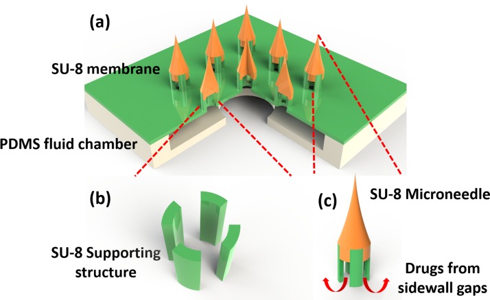
An array of 3 × 3 SU-8 supporting structures was patterned on a 140 μm thick, 6 mm × 6 mm SU-8 membrane (Fig. 1a). Each SU-8 supporting structure included four SU-8 pillars and was 350 μm high. The four pillars were patterned into a tubelike shape on the membrane (Fig. 1b). The inner diameter of the tube was 150 μm, while the outer diameter was 300 μm. SU-8 needles of 700 μm height were created on the top of SU-8 supporting structures to ensure the ability of transdermal penetration. Two PDMS layers were bonded with SU-8 membrane to form a sealed chamber for storing drugs from the connection tube. Once the microneedles entered into the tissue, drugs could be delivered into the body through the sidewall gaps between the pillars (Fig. 1c).
Figure 1.
Schematic illustration of the SU-8 microneedles. (a) Overview of the whole device; (b) SU-8 supporting structures made of 4 SU-8 pillars; and (c) enlarged view of a single SU-8 microneedle.
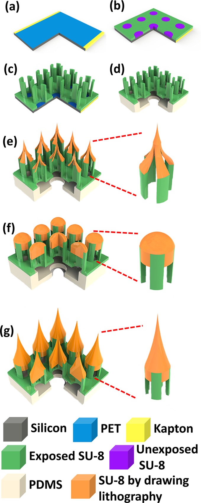
The fabrication process of SU-8 microneedles is shown in Fig. 2. SU-8 microneedles fabrication started from a layer of Polyethylene Terephthalate (PET, 3M, USA) film pasted on the Si substrate by sticking the edge area with kapton tape (Fig. 2a). The PET film, a kind of transparent film with poor adhesion to SU-8, was used as a sacrificial layer to dry release the final device from Si substrate. A 140 μm thick SU-8 layer was deposited on the top of this PET film. To ensure a uniform surface of this thick SU-8 layer, the SU-8 deposition was conducted in two steps coating. After exposed under 450 mJ/cm2 UV, the membrane pattern could be defined (Fig. 2b). In order to ensure an even surface for following spinning process, another 350 μm SU-8 layer was directly deposited on this layer in two steps without development. With careful alignment, an exposure of 650 mJ/cm2 UV energy was performed on this 350 μm SU-8 layer to define the SU-8 supporting structures (Fig. 2c). The SU-8 structure could be easily released from the PET substrate by removing the kapton tape and slightly bending the PET film. Two PDMS layers were bonded with this SU-8 structure by a method reported by Zhang et al.38 (Fig. 2d).
Figure 2.
Fabrication process for SU-8 microtubes. (a) Attaching a PET film on the Si substrate; (b) exposing the first layer of SU-8 membrane without development; (c) depositing and patterning two continuous SU-8 layers as sidewall pillars; (d) releasing the SU-8 structure from the substrate and bonding it with PDMS; (e) drawing hollowed microneedles on the top of supporting structures; (f) baking and melting the hollowed microneedles to allow the SU-8 flow in the gaps between pillars; and (g) drawing second time on the top of the melted SU-8 flat surface to get microneedles.
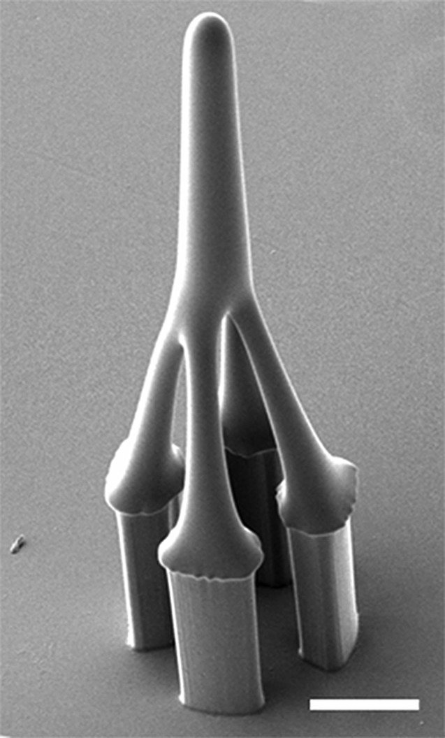
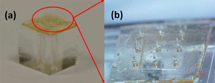
In our previous work,39 we used one time stepwise controlled drawing lithography technology for the sharp tips integration. However, since the frame used to conduct drawing process in present study is a four-pillars structure rather than a microtube, the conventional drawing process can only make a hollowed tip but not a solid tip structure (Fig. 3). This kind of tip was fragile and could not penetrate skin in the practical testing process. To solve the problem, we developed an innovative double drawing lithography process. After bonding released SU-8 structure with PDMS layers (Fig. 2d), we used it to conduct first time stepwise controlled drawing lithography37 and got hollowed tips (Fig. 2e). Briefly, the SU-8 was spun on the Si substrate and kept at 95 °C until the water inside completely vaporized. Device of SU-8 supporting structures was fixed on a precision stage. Then, the SU-8 supporting structures were immersed into the SU-8 by adjusting the precision state. The SU-8 were coated on the pillars' surface. Then, the SU-8 supporting structures were drawn away from the interface of the liquid maltose and air. After that, the temperature and drawing speed were increased. Since the SU-8 was less viscous at higher temperature, the connection between the SU-8 supporting structures and surface of the liquid SU-8 became individual SU-8 bridge, shrank, and then broke. The end of the shrunk SU-8 bridge forms a sharp tip on the top of each SU-8 supporting structure when the connection was separated. After the hollowed tips were formed in the first step drawing process, the whole device was baked on the hotplate to melt the hollowed SU-8 tips. Melted SU-8 reflowed into the gaps between four pillars and the tips became domes (Fig. 2f). Then, a second drawing process was conducted on the top of melted SU-8 to form sharp and solid tips (Fig. 2g). The final fabricated device is shown in Fig. 4.
Figure 3.
A hollowed SU-8 microneedle fabricated by single drawing lithography technology (scale bar is 100 μm).
Figure 4.
Optical images for the finished SU-8 microneedles.
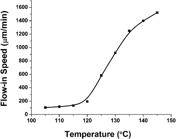
During the double drawing process, as long as the heated time and temperature were controlled, the SU-8 flow-in speed of SU-8 inside the gaps could be precisely determined. The relationship between baking temperature and flow-in speed was studied. As shown in Fig. 5, the flow-in speed is positive related to the baking temperature. The explanation for this phenomena is that the SU-8's viscosity is different under different baking temperatures.40 Generally, baked SU-8 has 3 status when temperature increases, solid, glass, and liquid. The corresponding viscosity will decrease and the SU-8 can also have higher fluidity. When the baking temperature is larger than 120 °C, the flow-in speed will increase sharply. But, if the baking temperature is higher, the SU-8 will reflow in the gaps too fast, which makes the flow-in depth hard to be controlled. There is a high chance that the whole gaps will be blocked, and no drugs can flow through these gaps any more. Considering that the total SU-8 supporting structure is only 350 μm high, we choose 125 °C as baking temperature for proper SU-8 flow-in speed and easier SU-8 flow-in depth control.
Figure 5.
The relationship between flow-in speed and baking temperature.
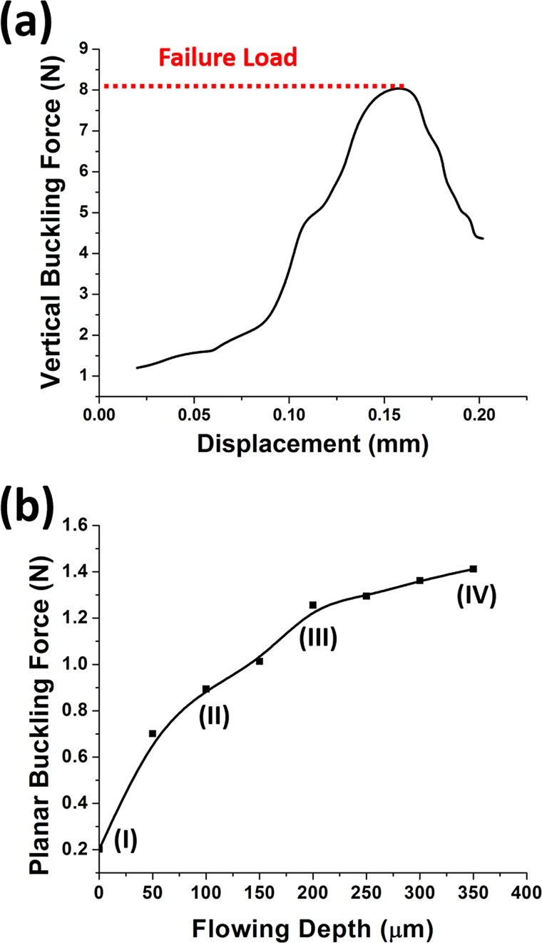
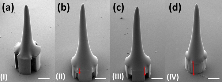
To ensure the adequate stiffness of the SU-8 microneedles in vertical direction, Instron Microtester 5848 (Instron, USA) was deployed to press the microneedles with the similar method reported by Khoo et al.41 As shown in Fig. 6a, the vertical buckling force was as much as 8.1N, which was much larger than the reported minimal required penetration force.42 However, in the previous practical testing experiments, even though the microneedles were strong enough in vertical direction, the planar shear force induced by skin deformation might also break the interface between SU-8 pillars and top tips. In our new device with four pillars supporting structure, the SU-8 could flow inside the sidewall gaps between the pillars to form anchors. These anchors could enhance microneedles' mechanical strength and overcome the planar shear force problems. Moreover, the anchors strength could be improved by controlling the SU-8 flow-in depth. Fig. 7 shows that the flow-in depth increases when the baking time increases as the baking time increases at 125 °C. Fig. 6b shows that the corresponding planar buckling force can be improved to be larger than 1 N by increasing flow-in depth. Some sidewall gaps at bottom are kept on purpose for drugs delivery; hence, the flow-in depth is chosen as 200 μm.
Figure 6.
(a) Measurement of the vertical buckling force. (b) The planar buckling force varies under different flow-in depth (I, II, III, and IV corresponding to the certain images in Fig. 7).
Figure 7.
Different flow-in depth inside the gaps between SU-8 pillars. (a) 0 μm; (b) 100 μm; (c) 200 μm; and (d) 350 μm (scale bar is 100 μm).
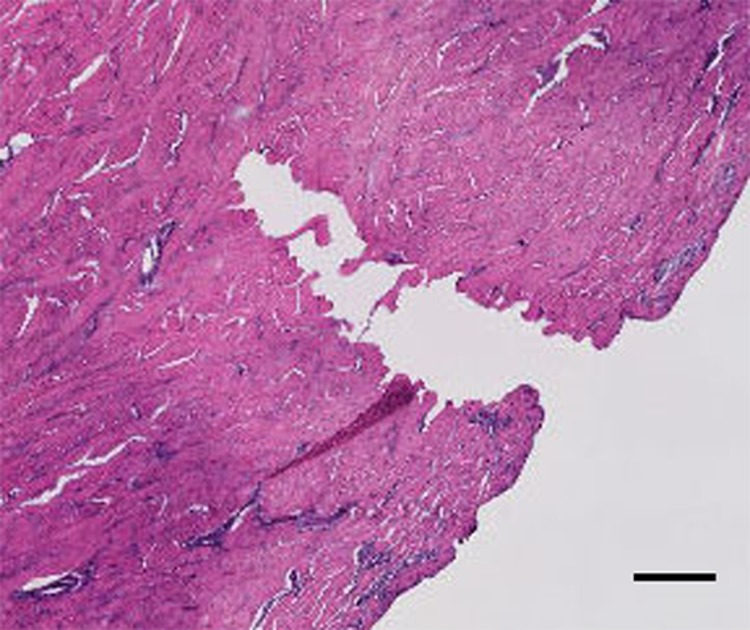
The penetration capability of the 3 × 3 SU-8 microneedles array is characterized by conducting the insertion experiment on the porcine cadaver skin. 10 microneedles devices were tested and all of them were strong enough to be inserted into the tissue without any breakage. Histology images of the skin at the site of one microneedle penetration were derived to prove that the sharp conical tip was not broken during the insertion process (Fig. 8). It also shows penetrated evidence because the hole shape is the same as the sharp conical tip.
Figure 8.
Histology image of individual microneedle penetration (scale bar is 100 μm).
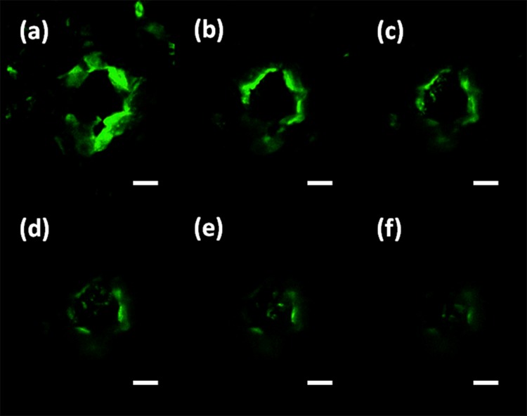
In order to verify that the drug solution can be delivered into tissue from the sidewall gaps of the microneedles, FITC (Fluorescein isothiocyanate) (Sigma Aldrich, Singapore) solution was delivered through the SU-8 microneedles after they were penetrated into the mouse cadaver skin. The representative results were then investigated via a confocal microscope (Fig. 9). The permeation pattern of the solution along the microchannel created by microneedles confirmed the solution delivery results. The black area was a control area without any diffused florescent solution. In contrast, the illuminated area in Fig. 9 indicates the area where the solution has diffused to it. These images were taken consecutively from the skin surface down to 180 μm with 30 μm intervals. The diffusion area had a similar dimension with the inserted microneedles. It has proved that the device can be used to deliver drugs into the body.
Figure 9.
Images of confocal microscopy to show the florescent solution is successfully delivered into the tissue underneath the skin surface. (a) 30 μm; (b) 60 μm; (c) 90 μm; (d) 120 μm; (e) 150 μm; and (f) 180 μm (scale bar is 100 μm).
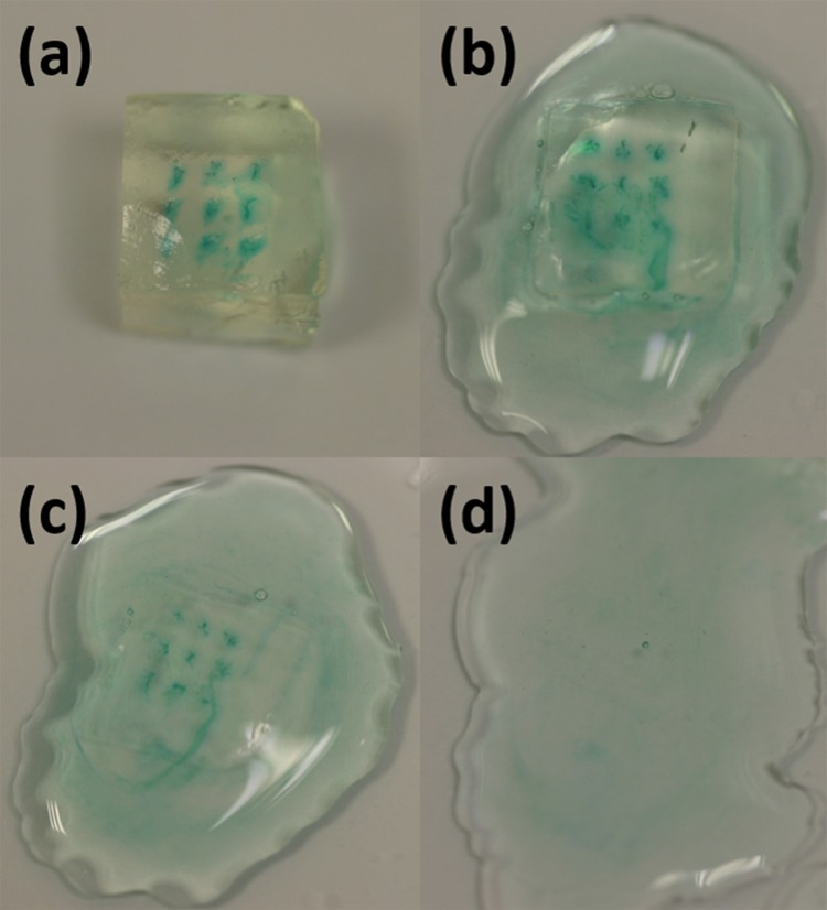
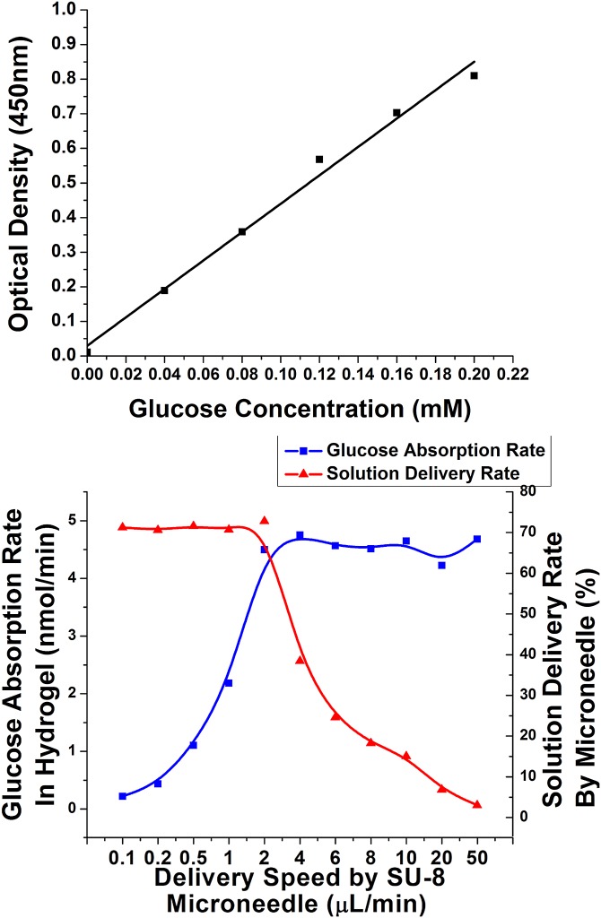
Due to the uneven surface of deformed skin, there is always tiny gap happened between tips of some microneedles and local surface skin. The microneedles could not be entirely inserted into the tissue. Drugs might leak to the skin surface through the sidewall gaps under certain driven pressure. Hydrogel absorption experiment was conducted to quantify the delivery rate (i.e., the ratio of solution delivered into tissues in the total delivered volume) and to optimize the delivery speed. Using hydrogel as the tissue model for quantitative analysis of microneedle releasing process was reported by Tsioris et al.43 The details are shown here. Gelatin hydrogel was prepared by boiling 70 ml DI (Deionized) water and mixing it with 7 g of KnoxTM original unflavored gelatin powder. The solution was poured into petri dish to 1 cm high. Then, the petri dish was put into a fridge for half an hour. Gelatin solution became collagen slabs. The collagen slabs were cut into 6 mm × 6 mm sections. A piece of fully stretched parafilm (Parafilm M, USA) was tightly mounted on the surface of the collagen slabs. This parafilm was used here to block the leaked solution further diffusing into the collagen slab in the delivery process. Then, the microneedles penetrated the parafilm and went into the collagen slab. Controlled by a syringe pump, 0.1 ml–0.5 mg/ml glucose solution was delivered into the collagen slab under different speeds. Methylene Blue (Sigma Aldrich, Singapore) was mixed into the solution for better inspection purpose (Fig. 10a). Then, the collagen slabs was digested in 1 mg/ml collagenase (Sigma Aldrich, Singapore) at room temperature (Fig. 10b). It took around 1 h that all the collagen slabs could be fully digested (Fig. 10d). The solution was collected to measure the glucose concentration with glucose detection kit (Abcam, Singapore). Briefly, both diluted glucose standard solution and the collected glucose solution were added into a series of wells in a well plate. Glucose assay buffer, glucose enzyme, and glucose substrate were mixed with these samples in the wells. After incubation for 30 min, their absorbance were examined by using a microplate reader at a wavelength of 450 nm. By comparing the readings with the measured concentration standard curve (Fig. 11a), the glucose concentration in the hydrogel, the glucose absorption rate in the hydrogel, and the solution delivery rate by microneedles could be measured and calculated. As shown in Fig. 11b, when the delivering speed of a single microneedle increased from 0.1 μl/min to 2 μl/min, the glucose absorption rate also increased. Most of the glucose solution from microneedles could go into the hydrogel. The delivered rate could be as high as 71%. The rest solution leaked from sidewall gaps and blocked by parafilm. However, when the delivered speed for a single microneedle was larger than 2 μl/min, the hydrogel absorption rate was saturated. More and more solution could not go into the hydrogel but leak from the sidewall gaps. Then, the delivered rate decreased. Therefore, 2 μl/min was chosen as the optimized delivery speed for the microneedle.
Figure 10.
Glucose solution could be delivered into the hydrogel, and the collagen stabs were dissolved by collagenase.
Figure 11.
(a) Standard curve for glucose detection; (b) glucose absorption rate and solution delivery rate in a single needle corresponding to different delivery speed.
In conclusion, a drug delivery device of integrated vertical SU-8 microneedles array is fabricated based on a new double drawing lithography technology in this study. Compared with the previous biocompatible polymer-based microneedles fabrication technology, the proposed fabrication process is scalable, reproducible, and inexpensive. The fabricated microneedles are rather strong along both vertical and planar directions. It is proved that the microneedles were penetrated into the pig skin easily. The feasibility of drug delivery using SU-8 microneedles is confirmed by FITC fluorescent delivery experiment. In the hydrogel absorption experiment, by controlling the delivery speed under 2 μl/min per microneedle, the delivery rate provided the microneedle is as high as 71%. In the next step, the microneedles will be further integrated with microfluidics on a flexible substrate, forming a skin-patch like drug delivery device, which may potentially demonstrate a self-administration function. When patients need an injection treatment at home, they can easily use such a device just like using an adhesive bandage strip.
Acknowledgments
This work was supported by the ARF-Tier2 from Ministry of Education (MOE) under Grant Nos. R-263000598112 and R-398000068112 and by National Research Foundation (NRF), Singapore, under the NRF2011NRF-CRP001-057 Program (WBS:R263000A27281).
References
- Folch A., Annu. Rev. Biomed. Eng. 2, 227 (2000). 10.1146/annurev.bioeng.2.1.227 [DOI] [PubMed] [Google Scholar]
- Whitesides G. M., Nature 442, 368 (2006). 10.1038/nature05058 [DOI] [PubMed] [Google Scholar]
- Craighead H., Nature 442, 387 (2006). 10.1038/nature05061 [DOI] [PubMed] [Google Scholar]
- El-Ali J., Sorger P. K., and Jensen K. F., Nature 442, 403 (2006). 10.1038/nature05063 [DOI] [PubMed] [Google Scholar]
- Khademhosseini A., Langer R., Borenstein J., and Vacanti J. P., Proc. Natl. Acad. Sci. U.S.A. 103, 2480 (2006). 10.1073/pnas.0507681102 [DOI] [PMC free article] [PubMed] [Google Scholar]
- Polla D. L., Erdman A. G., Robbins W. P., Markus D. T., Diaz-diaz J., Rizq R., Wang A., and Krulevitch P., Annu. Rev. Biomed. Eng. 2, 551 (2000). 10.1146/annurev.bioeng.2.1.551 [DOI] [PubMed] [Google Scholar]
- LaVan D. A., McGuire T., and Langer R., Nat. Biotechnol. 21, 1184 (2003). 10.1038/nbt876 [DOI] [PubMed] [Google Scholar]
- Zahn J. D., Talbot N. H., LiePmann D., and Pisano A. P., Biomed. Microdevices 2, 295 (2000). 10.1023/A:1009907306184 [DOI] [Google Scholar]
- Sullivan S. P., Koutsonanos D. G., Martin M. D. P., Lee J. W., Zarnitsyn V., Choi S.-O., Murthy N., Compans R. W., Skountzou I., and Prausnitz M. R., Nat. Med. 16, 915 (2010). 10.1038/nm.2182 [DOI] [PMC free article] [PubMed] [Google Scholar]
- Shah U. U., Roberts M., Orlu Gul M., Tuleu C., and Beresford M. W., Int. J. Pharm. 416, 1 (2011). 10.1016/j.ijpharm.2011.07.002 [DOI] [PubMed] [Google Scholar]
- Prausnitz M. R., Adv. Drug Delivery Rev. 56, 581 (2004). 10.1016/j.addr.2003.10.023 [DOI] [PubMed] [Google Scholar]
- Lo W., Ghazaryan A., Tso C.-H., Hu P.-S., Chen W.-L., Kuo T.-R., Lin S.-J., Chen S.-J., Chen C.-C., and Dong C.-Y., Appl. Phys. Lett. 100, 213701 (2012). 10.1063/1.3701135 [DOI] [Google Scholar]
- Wilke N., Mulcahy A., Ye S.-R., and Morrissey A., Microelectron. J. 36, 650 (2005). 10.1016/j.mejo.2005.04.044 [DOI] [Google Scholar]
- Gill H. S., Denson D. D., Burris B. A., and Prausnitz M. R., Clin. J. Pain 24, 585 (2008). 10.1097/AJP.0b013e31816778f9 [DOI] [PMC free article] [PubMed] [Google Scholar]
- Matriano J. A., Cormier M., Johnson J., Young W. A., Buttery M., Nyam K., and Daddona P. E., Pharm. Res. 19, 63 (2002). 10.1023/A:1013607400040 [DOI] [PubMed] [Google Scholar]
- Omatsu T., Chujo K., Miyamoto K., Okida M., Nakamura K., Aoki N., and Morita R., Opt. Express 18, 17967 (2010). 10.1364/OE.18.017967 [DOI] [PubMed] [Google Scholar]
- Mansoor I., Liu Y., Häfeli U. O., and Stoeber B., J. Micromech. Microeng. 23, 085011 (2013). 10.1088/0960-1317/23/8/085011 [DOI] [Google Scholar]
- Yang M. and Zahn J. D., Biomed. Microdevices 6, 177 (2004). 10.1023/B:BMMD.0000042046.07678.2e [DOI] [PubMed] [Google Scholar]
- Jin C. Y., Han M. H., Lee S. S., and Choi Y. H., Biomed. Microdevices 11, 1195 (2009). 10.1007/s10544-009-9337-1 [DOI] [PubMed] [Google Scholar]
- Chaudhri B. P., Ceyssens F., De Moor P., Van Hoof C., and Puers R., J. Micromech. Microeng. 20, 064006 (2010). 10.1088/0960-1317/20/6/064006 [DOI] [Google Scholar]
- Yoon Y., Park J., and Allen M. G., J. Microelectromech. Syst. 15, 1121 (2006). 10.1109/JMEMS.2006.879669 [DOI] [Google Scholar]
- Moon S. J. and Lee S. S., J. Micromech. Microeng. 15, 903 (2005). 10.1088/0960-1317/15/5/002 [DOI] [Google Scholar]
- Pérennès F., Marmiroli B., Matteucci M., Tormen M., Vaccari L., and Di Fabrizio E., J. Micromech. Microeng. 16, 473 (2006). 10.1088/0960-1317/16/3/001 [DOI] [Google Scholar]
- You S.-K., Noh Y.-W., Park H.-H., Han M., Lee S. S., Shin S.-C., and Cho C.-W., J. Drug Target. 18, 15 (2010). 10.3109/10611860903115274 [DOI] [PubMed] [Google Scholar]
- Oh J.-H., Park H.-H., Do K.-Y., Han M., Hyun D.-H., Kim C.-G., Kim C.-H., Lee S. S., Hwang S.-J., Shin S.-C., and Cho C.-W., Eur. J. Pharm. Biopharm. 69, 1040 (2008). 10.1016/j.ejpb.2008.02.009 [DOI] [PubMed] [Google Scholar]
- Kolli C. S. and Banga A. K., Pharm. Res. 25, 104 (2008). 10.1007/s11095-007-9350-0 [DOI] [PubMed] [Google Scholar]
- Li G., Badkar A., Nema S., Kolli C. S., and Banga A. K., Int. J. Pharm. 368, 109 (2009). 10.1016/j.ijpharm.2008.10.008 [DOI] [PubMed] [Google Scholar]
- Aoyagi S., Izumi H., and Fukuda M., Sens. Actuators, A 143, 20 (2008). 10.1016/j.sna.2007.06.007 [DOI] [Google Scholar]
- Choi C. K., Kim J. B., Jang E. H., Youn Y.-N., and Ryu W. H., Small 8, 2483 (2012). 10.1002/smll.201200441 [DOI] [PubMed] [Google Scholar]
- Prausnitz M. R. and Langer R., Nat. Biotechnol. 26, 1261 (2008). 10.1038/nbt.1504 [DOI] [PMC free article] [PubMed] [Google Scholar]
- Wang P.-C., Paik S.-J., Kim J., Kim S.-H., and Allen M. G., in 2011 IEEE 24th International Conference on Micro Electro Mechanical Systems (MEMS) (IEEE, 2011), pp. 1039–1042. [Google Scholar]
- Moga K. A, Bickford L. R., Geil R. D., Dunn S. S., Pandya A. A, Wang Y., Fain J. H., Archuleta C. F., O'Neill A. T., and Desimone J. M., Adv. Mater. 25(36), 5060 (2013). 10.1002/adma.201300526 [DOI] [PMC free article] [PubMed] [Google Scholar]
- Yung K. L., Xu Y., Kang C., Liu H., Tam K. F., Ko S. M., Kwan F. Y., and Lee T. M. H., J. Micromech. Microeng. 22, 015016 (2012). 10.1088/0960-1317/22/1/015016 [DOI] [Google Scholar]
- Choi Y., McClain M. A, LaPlaca M. C., Frazier A. B., and Allen M. G., Biomed. Microdevices 9, 7 (2007). 10.1007/s10544-006-9004-8 [DOI] [PubMed] [Google Scholar]
- Yoon Y.-K., Park J.-H., Lee J.-W., Prausnitz M. R., and Allen M. G., J. Micromech. Microeng. 21, 025014 (2011). 10.1088/0960-1317/21/2/025014 [DOI] [Google Scholar]
- Park J.-H., Yoon Y.-K., Choi S.-O., Prausnitz M. R., and Allen M. G., IEEE Trans. Biomed. Eng. 54, 903 (2007). 10.1109/TBME.2006.889173 [DOI] [PubMed] [Google Scholar]
- Lee K., Lee H. C., Lee D.-S., and Jung H., Adv. Mater. 22, 483 (2010). 10.1002/adma.200902418 [DOI] [PubMed] [Google Scholar]
- Zhang Z., Zhao P., Xiao G., Watts B. R., and Xu C., Biomicrofluidics 5, 46503 (2011). 10.1063/1.3659016 [DOI] [PMC free article] [PubMed] [Google Scholar]
- Xiang Z., Wang H., Pant A., Pastorin G., and Lee C., Biomicrofluidics 7, 026502 (2013). 10.1063/1.4798471 [DOI] [PMC free article] [PubMed] [Google Scholar]
- Lee K. and Jung H., Biomaterials 33, 7309 (2012). 10.1016/j.biomaterials.2012.06.065 [DOI] [PubMed] [Google Scholar]
- Khoo H. S., Liu K.-K., and Tseng F.-G., J. Micromech. Microeng. 13, 822 (2003). 10.1088/0960-1317/13/6/305 [DOI] [Google Scholar]
- Olatunji O., Das D. B., Garland M. J., Belaid L. U. C., and Donnelly R. F., J. Pharm. Sci. 102, 1209 (2013). 10.1002/jps.23439 [DOI] [PubMed] [Google Scholar]
- Tsioris K., Raja W. K., Pritchard E. M., Panilaitis B., Kaplan D. L., and Omenetto F. G., Adv. Funct. Mater. 22, 330 (2012). 10.1002/adfm.201102012 [DOI] [Google Scholar]


