

Abstract
The importance and advantages of three-dimensional (3D) cell cultures have been well-recognized. Tumor cells cultured in a 3D culture system as multicellular tumor spheroids (MTS) can bridge the gap between in vitro and in vivo anticancer drug evaluations. An in vitro 3D tumor model capable of providing close predictions of in vivo drug efficacy will enhance our understanding, design, and development of better drug delivery systems. Here, we developed an in vitro 3D tumor model by adapting the hydrogel template strategy to culture uniformly sized spheroids in a hydrogel scaffold containing microwells. The in vitro 3D tumor model was to closely simulate an in vivo solid tumor and its microenvironment for evaluation of anticancer drug delivery systems. MTS cultured in the hydrogel scaffold are used to examine the effect of culture conditions on the drug responses. Free MTS released from the scaffold are transferred to a microfluidic channel to simulate a dynamic in vivo microenvironment. The in vitro 3D tumor model that mimics biologically relevant parameters of in vivo microenvironments such as cell-cell and cell-ECM interactions, and a dynamic environment would be a valuable device to examine efficiency of anticancer drug and targeting specificity. These models have potential to provide in vivo correlated information to improve and optimize drug delivery systems for an effective chemotherapy.
Keywords: 3D tumor model, multicellular tumor spheroids, hydrogel, microfluidic channel, drug delivery systems
INTRODUCTION
In vitro cell culture methods have been very easy and economical in elucidating complex cellular mechanisms. In tissue culture systems, the 2-dimensional (2D) cellular microenvironment is very different from in vivo conditions where cells are exposed to the three-dimensional (3D) environment. In addition, tumor cells in vivo are exposed to a controlled 3D microenvironment that is tightly regulated with respect to interactions with the surrounding cells, growth factors, and extracellular matrix (ECM) molecules.1 Hence, an in vivo 3D microenvironment must be closely mimicked in the in vitro conditions to understand the tumor microenvironment and to develop drug delivery systems.
In cancer research, an in vitro tumor model is a valuable and essential tool for the assessment of therapeutic drug efficiency prior to in vivo studies. The development of clinically translatable drug delivery systems requires thorough evaluation of their in vitro tumor targeting efficiency, therapeutic efficacy, cytotoxicity, and biocompatibility. The in vitro therapeutic efficacy of anticancer drugs is generally evaluated by using flat 2D cellular monolayers cultured in a plastic tissue culture flask as opposed to expensive and arduous in vivo studies. The dependence of in vivo drug efficacy on tumor microenvironments is not well understood because of the morphological differences of the tumor cells and the lack of cell-cell and cell-extracellular matrix interactions in 2D cultures.2–4 In an effort to bridge the gap between in vitro and in vivo drug evaluations, several methods have been developed to culture tumor cells in three dimensions as multicellular spheroids for better simulation of solid tumors. Some of the methods to culture multicellular tumor spheroids (MTS) include hanging drop, liquid layover, rotary bioreactor, and the use of ECM scaffolds.5–11 Studies using MTS reported discrepancies in anticancer drug responses in comparison to monolayer models.12–15 The importance and advantages of 3D cell cultures have been well-recognized and are presently being explored for developing efficient anticancer drug delivery systems.5,16–18 Although drug responses of the MTS demonstrated a very close resemblance to in vivo solid tumors, in many cases, the impact of the in vivo extracellular environment on a drug delivery system is often disregarded. An in vitro 3D tumor model capable of providing close predictions of in vivo drug efficacy will enhance our understanding, design, and development of better drug delivery systems15.19 Consequently, it is vital to develop in vitro 3D tumor models to minimize disparities of drug efficacies between the in vitro and in vivo studies.
The purpose of this study was to develop an in vitro 3D tumor model as a tool for evaluating therapeutic efficiency of an anticancer drug. In our study, we demonstrated (1) the culture of uniformly sized MTS in a hydrogel scaffold containing microwells and (2) further applications in a microfluidic channel to evaluate therapeutic efficiency of doxorubicin (DOX), an anthracycline antibiotic which intercalate DNA.16 The hydrogel scaffold was fabricated to contain microwells of predefined geometry and dimensions in which tumor cells formed MTS. MTS were used to examine the effect of culture condition and distribution of the anticancer drug. MTS removed from the scaffold are loaded in a microfluidic channel simulating dynamic fluidic movement of in vivo microenvironment. Drug distribution and therapeutic efficiency have been monitored by light and fluorescence microscopes.
MATERIALS AND METHODS
Materials
Gelatin, type A, from porcine, fetal bovine serum (FBS), bovine serum albumin (BSA), and doxorubicin hydrochloride were obtained from Sigma-Aldrich Chemical Co. (St. Louis, MO). Glutaraldehyde, EM grade was obtained from Polysciences, Inc. (Warrington, PA). Human breast cancer cells MCF-7 were obtained from ATCC (Manassas, VA). Dulbecco’s modified Eagle’s medium (DMEM), trypsin/EDTA, Dulbecco’s phosphate buffered saline (DPBS), penicillin/streptomycin, and l-glutamine were obtained from GIBCO (Carlsbad, CA). Phenol-free Matrigel was obtained from BD Biosciences (San Jose, CA). Primary antibodies, α-6 integrin (rabbit oligoclonal), and E-cadherin (mouse monoclonal) were obtained from Invitrogen (Camarillo, CA); CellMask, Alexa fluor conjugated secondary antibodies, DAPI, and a Live/Dead viability/cytotoxicity kit for mammalian cells were obtained from Molecular Probe (Carlsbad, CA). A photoresist SU-8 (2075) and developer were obtained from MicroChem (Newton, MA). Polydimethylsiloxane (PDMS) was purchased as Sylgard 184 kit from Dow Corning (Midland, MI).
Fabrication of a Master Template and a Hydrogel Scaffold
A master template was fabricated by photolithography as described previously and soft lithography using polydimethylsiloxane (PDMS).20,21 First a silicon wafer was fabricated to contain molds of predetermined size and shape. Then the mixed silicon elastomer base and curing agent (10:1, w/w ratio) was poured onto the silicon wafer containing molds and cured at 100 °C for 1 h. A PDMS mater template contained circular posts of 50 µm diameter and 30 µm height.
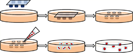
This master template was used to imprint patterns on the hydrogel scaffold as displayed in Figure 1A. A warm gelatin solution (30% w/v, 10 mL, pH adjusted with 2 M HCl) was mixed with glutaraldehyde (1% v/v, final concentration). The gelatin solution was transferred onto the master template containing posts and kept at 60 °C for 2 h. Upon removing the master template, the cross-linked hydrogel scaffold containing wells was placed in a Petri dish then rinsed with PBS-100 mM glycine three times and sterilized in 70% ethanol solution. Before the cell seeding, the template was rinsed with DPBS and culture medium. Glutaraldehyde, a common cross-link agent due to its easy handling and effective and rapid cross-linking ability stabilized gelatin and prevented disintegration and degradation in aqueous solution.22 In spite of known cytotoxicity of glutaraldehyde, bioprostheses cross-linked with glutaraldehyde have been clinically accepted.23
Figure 1.

Overall schematic of fabrication of a hydrogel scaffold containing microwells and formation of MTS consisting of MCF-7 cells. (A) A master template was pressed into the gelatin solution mixed with HCl and glutaraldehyde followed by warming at 60 °C to allow cross-linking. Upon removal of the master template, the hydrogel scaffold containing microwells was rinsed prior to cell seeding. (B) MCF-7 cells suspended in 50% Matrigel solution were transferred onto the hydrogel scaffold. After MTS were formed, Matrigel encapsulating MTS were released from the hydrogel scaffold.
Cell Culture and MTS Formation
Human breast cancer cells, MCF-7, were maintained in DMEM supplemented with 10% FBS, 100 IU/mL penicillin, 100 µg/mL streptomycin, and 2 mM l-glutamine. The MCF-7 cells were incubated at 37 °C with 5% CO2, and the growth medium was exchanged every other day. At 90% confluency, cells were trypsinized, centrifuged (Eppendorf, Germany), and resuspended in ice-cold 50% Matrigel so that the cell concentration was 1 × 10⁶ cells per mL. An aliquot of MCF-7 suspension was transferred onto the surface of the hydrogel scaffold as shown in Figure 1B. The surface of the scaffold was gently swiped across aiding cells to settle within the microwells. After one hour of incubation at 37 °C, the culture medium was added to the culture vessel and maintained at 37 °C with 5% CO2. The MTS formation was observed using a phase contrast microscope (Eclipse TS100, Nikon, Japan). To release MTS from the hydrogel, the MTS were rinsed with chilled serum-free medium or DPBS. Gentle agitation or scraping the surface with a cell scraper assisted in the removal of the MTS from the microwells and the MTS in solution were collected in a microcentrifuge tube and centrifuged for 60 s.
Scanning Electron Microcopy (SEM) and Immunofluorescence of MTS
All stages of characterization were performed at room temperature unless noted otherwise. For SEM images, the MTS were fixed with 4% glutaraldehyde and postfixed with 1% osmium tetroxide. The specimens were dehydrated with serial concentrations of ethanol. After critical point drying in liquid CO2 and gold sputter coating, the MTS were imaged using JSM-840 (JEOL Ltd., Japan).
For fluorescence images, the plasma membranes of the MCF-7 cells consisting of MTS were stained with CellMask orange stain (5 µg/mL, Ex/Em: 554 nm/567 nm) to distinguish individual cells within the MTS. For immunofluorescence images, the MTS were fixed with 4% formaldehyde and permeabilized with 0.1% Triton X-100. After blocking with 3% BSA in staining buffer for 2 h, primary antibodies were applied against: α-6 integrin (1:100) and E-cadherin (1:100). Fluorophore-conjugated secondary antibodies, Alexa fluor 488 goat antirabbit IgG (1:400), and Alexa fluor 630 goat antimouse IgG (1:400) were added. All staining buffers contained 0.2% Triton X-100, 0.1% BSA, and 0.05% Tween 20 in PBS. Fluorescence images were obtained using a confocal laser scanning microscope (Olympus FV1000/IX81, Japan) with 488 nm, 563 nm, and 647 nm laser lines equipped. Images were postprocessed using FV10-ASW 3.1.
Fabrication of a Microfluidic Channel and Experimental Setup
The microfluidic channel containing center and side channels was fabricated with a negative photoresist, SU-8 2075, and PDMS by standard photolithography technique (Figure 2A). First, a SU-8 photoresist layer was spin-coated onto the surface of a silicon wafer (University Wafer; South Boston, MA). After exposure to UV light through a photomask containing a pattern of the microfluidic channel, the undesired sections of the SU-8 layer were etched. The PDMS solution was poured into a SU-8 mold and cured. Then, the PDMS layer was peeled off, and then inlet and outlet ports were punched on the left and right sides of the microfluidic channel, respectively. The PDMS layer was treated with oxygen plasma and bonded with a glass slide to form the microfluidic channel. As shown in Figure 2B, the center channel located in between two side channels was to be filled with MTS. Fresh culture medium was constantly provided through both side channels to the center channel by diffusion. The width, length, and height of the center channel were measured at 900 µm, 2700 µm, and 100 µm, respectively, and the total volume of the center channel was 243 nL. The width of the side channel was 300 µm. Square PDMS pillars (100 µm × 100 µm) located on the upper and lower sides of the center channel were lined every 100 µm to set boundaries between the side and the center channels. The fabricated chip was placed on a microscope incubator stage (Okolab, Italy) to maintain 37 °C and 5% CO2 and the inlet and outlet ports were connected via tubing to syringes containing culture medium and vials, respectively (Figure 2C). For real-time observation of cellular behaviors in the microfluidic channel, an inverted microscope (Olympus IX71, Japan) was used.
Figure 2.

Overall schematic of a microfluidic channel and experimental setup. (A) Schematic of fabrication of a microfluidic channel. (B) Design and bright field image of the microfluidic channel. The black arrow shows the direction of medium flow. Scale bar: 300 µm. (C) Schematic of experimental setup of the microfluidic channel.
To load the MTS in the microfluidic channel, the free MTS were resuspended in ice-cold Matrigel solution (50% v/v Matrigel in DMEM), then added to the reservoir located at the inlet of the center channel. Negative pressure through the outlet of the channel was applied which allowed MTS-Matrigel mixture to leave the reservoir and fill the center channel. Once the center channel was filled, the microfluidic channel was incubated for one hour allowing the Matrigel to polymerize. The culture medium was constantly supplied through both side channels by a programmed syringe pump, and the medium flow velocity was set at 30 µL/h, equivalent to 278 µm/s. This value was obtained based on the blood fluid velocity in tumor, 100–800 µm/s.24
Cytotoxicity of DOX in the 3D Tumor Model
Cytotoxicity of DOX was evaluated in vitro in the 3D tumor model. Two forms of DOX were studied; water-soluble doxorubicin hydrochloride (DOX-HCl) and DOX loaded disulfide bonded methoxypoly(ethylene glycol)-(cysteine)4-poly(d,l-lactic acid) micelles were synthesized and provided by Seung-Young Lee (Purdue University, West Lafayette, IN). Lee et al. reported that the DOX micelles were approximately 112 ± 62 nm in size, and the drug loading content was 6.9% w/w.25 To treat the MTS in a static condition, either DOX-HCl (0.5 µM) or DOX micelles (0.5 µM DOX equivalent) were directly added to the MTS. To study drug responses in the 3D tumor model, we prepared drug solutions of the concentration reported to produce a cytocidic effect on MCF-7 monolayers.26 After 24 h of drug treatment, the Live/Dead viability/cytotoxicity kit was used as according to the manufacturer’s procedure to observe cytotoxicity of DOX using FV1000/IX81. Prior to the viability assay, MTS were rinsed with DPBS to remove any drugs present in the medium.
Treatment of DOX in the Microfluidic Channel
To study cytotoxicity of DOX in the dynamic condition, drug solutions were added to the both side channels after MTS/ Matrigel solution was loaded in the center channel. Drug solutions of DOX-HCI (0.5 µM) and DOX micelles (0.5 µM and 25 µM DOX equivalent) were prepared. The solution with a higher concentration of DOX micelles was used for the better fluorescence signal detection. During the drug treatment for 24 h on the incubation stage, the same flow velocity, 0.3 mm/s, was maintained. Time-lapse images of bright field and fluorescence were obtained to observe changes in fluorescence intensity.
RESULTS
Fabrication of the Hydrogel Scaffold Containing Microwells and Formation of the MTS
Hydrogel scaffolds containing microwells of predefined shape and size were fabricated as described previously with modification.20,21 The master template containing circular posts of 50 µm diameter and 30 µm height was fabricated by soft lithography using PDMS (Figure 3A). This PDMS master template was used to make patterns of circular wells on the surface of the hydrogel scaffold. The cross-linked hydrogel scaffold, upon removing the master template, contained the exact imprint of the template: circular wells, 50 µm in diameter and 30 µm in depth. The concentration of glutaraldehyde used as a cross-linking agent did not have a cytotoxic effect after quenching unreacted glutaraldehyde. Compared to the uncross-linked scaffold, the color of the cross-linked hydrogel scaffold was slightly brown but still remained transparent allowing microscopic observation (Figure 3B). The structural integrity of the microwells was maintained throughout the culturing period, although slight swelling of the hydrogel scaffold was observed during the rinse. Gentle scraping of the MCF-7 cells suspended in Matrigel solution facilitated cells to settle within microwells instead of adhering on the surface between microwells (Figure 3C). Matrigel, a thermo-sensitive hydrogel, that is, a solution at 4 °C and forming a hydrogel at 37 °C, avoided in situ polymerization requiring harmful chemicals or UV exposure. The MTS were easily freed from the microwells in the hydrogel scaffold and remained intact even after centrifugation and resuspension. Although MCF-7 cells could be cultured without the ECM in microwells, the MTS adding Matrigel into the cell suspension enhanced MTS formation and induced cell-ECM interactions. Matrigel, a solubilized basement membrane matrix extracted from Engelbreth-Holm-Swarm mouse sarcoma, is rich in laminin and widely used in 3D cell culture; cells form spheroids either embedded within or as “dripped” on the Matrigel coat.27,28 Although several thermally sensitive natural and synthetic polymers (e.g., collagen, Pluronic F172, poly(N-isopropylacrylamide)) were considered as ECM in culturing MTS, these polymers require a longer gelation time and are mechanically weak and opaque which prevents microscopic observation.
Figure 3.

Phase contrast microscopic images of microwells in the hydrogel scaffold and MCF-7 seeded in the hydrogel scaffolds. (A) The PDMS master template containing circular micropatterns of 50 µm diameter. (B) Cross-linked hydrogel scaffold containing 50 µm diameter microwells. (C) The MTS after 1 day of culture in the hydrogel scaffold and (D) image of the MTS in a microwell after 3 days of culture. (E) Free MTS released from the scaffold after 3 days of culture. Scale bar: 50 µm.
Characterization of the MTS
Various microscopic techniques were used to ensure the formation of the MTS cultured in the hydrogel scaffold. The SEM images obtained exhibited that the MTS exhibited different morphology in comparison to the loose aggregated cluster. Aggregated MCF-7 cells formed irregular shapes, and individual cells were visible (Figure 4A). In the MTS, it appeared that cells were tightly bound to each other, and no discernible individual cells were observed on the surface of MTS (Figure 4B). To observe the cellular arrangement within the MTS, plasma membranes were stained; optically sectioned images of the stained plasma membrane showed that individual cells were arranged tightly within the MTS (Figure 4C–D). For immunofluorescence images, plasma membrane molecules, α6-integrin, and E-cadherin were targeted with antibodies to characterize the cell–ECM and cell–cell interactions of the MTS. A laminin receptor mediating between cells and ECM, α6-integrin plays an important role in growth and survival of MCF-7 cells.29 α6-Integrin is also a marker for correctly distributed basolateral polarity in nonmalignant breast epithelium; disrupted basolateral polarity is found in malignant breast epithelium.28,30 The MTS cultured in the hydrogel scaffold expressed α6-integrin on the surface but scattered throughout the MTS indicating less organized basolateral polarity (Figure 4E). E-cadherin is an epithelial cell adhesion molecule found in the adherens junctions. It is essential to maintain adherent junction formation and tissue structure; the decrease in E-cadherin expression indicates loss of cell-cell adhesion, a common characteristic of invasive malignant cells.31,32 The presence of E-cadherin was observed between cells within the MTS indicating cells were not loosely bound (Figure 4F).
Figure 4.

Characterization of the MTS. (A) MCF-7 cells cultured in a scaffold-free environment. (B–F) MTS grown in the hydrogel scaffold containing microwells: (A) SEM image of the MCF-7 cells depicting morphological differences in a loosely aggregated form; (B) SEM image of the free MTS after 3 days of culture; (C and D) confocal fluorescence and bright field overlay images of the MTS revealing the tight packing of the cells (plasma membranes stained with CellMask shown in red); (E and F) optically sectioned immunofluorescence images of the MTS showing scattered signals of α6-integrin (E) and signals of E-cadherin between cells (F). Scale bars: (A and B) 10 µm and (C) 50 µm.
Culture of the 3D Tumor Model in a Microfluidic Channel
Fabricated microfluidic channel was employed in our study to provide dynamic fluidic movements to the MTS. Both side channels placed above and below the tumor interstitium channel were intended to simulate a dynamic in vivo microenvironment by providing constant flow of culture medium. The center channel area was filled with the MTS in Matrigel solution. Matrigel was diluted in culture medium (1:1, v/v) to decrease its viscosity for loading the MTS into the microfluidic channel.
When the MTS–Matrigel solution was added, boundaries created between the center and side channels were clearly visible. The channel was observed carefully to avoid air trapped in channels that could cause a compaction of Matrigel and blocking the flow. The polymerized Matrigel retained its ability to form a gel and maintain its mechanical strength throughout the experiment. Its transparency allows the MTS to be visualized without disintegrating the Matrigel. In the center channel, two columns located on the left, middle, and right sides functioned as anchors for the Matrigel to prevent rupturing when pressure was applied. Since the center channel could hold a very small volume of MTS-Matrigel, it was not practical to control the distribution of the MTS. Several MTS were scattered in the channel as seen in Figures 7A and 8A. It also appeared that the size of MTS varied; since MTS were cultured in the microwell with larger diameter, it was expected that the major axis of the MTS would be longer. The MTS appeared smaller when settled on its side in the microfluidic channel. During 24 h of incubation, active movement of the MTS was observed with constant flow of culture medium indicating cells were viable (Figure S1 in the Supporting Information).
Figure 7.

Bright-field image of the MTS in the microfluidic channel. (A) The MTS in Matrigel prior to DOX-HCl treatment. (B) Real-time, enlarged views of the MTS are outlined in a white dotted box in (A) during 24 h of treatment with DOX-HCl. The MTS appeared to lose its spheroidal shape over time. Scale bar: 50 µm.
Figure 8.

Bright field images of the MTS in the microfluidic channel. (A) The MTS in Matrigel prior to DOX micelle treatment at 25 µM DOX equivalent concentration. (B and C) Enlarged views of the MTS outlined in white and black dotted box in (A), respectively, during 24 h of treatment with DOX micelles. Scale bar: 100 µm.
Cytotoxicity of DOX in the 3D Tumor Model
To study cytotoxicity in the 3D tumor model, FDA approved doxorubicin (DOX) was used as a model anticancer drug. In addition to its therapeutic effect on breast cancer, autofluorescent DOX enabled monitoring of the drug using a fluorescence microscope. After the treatment with either DOX-HCl or DOX micelles in the static culture condition, fluorescence images of the tumor models were acquired to observe drug accumulation or distribution. Accumulation of DOX-HCl in the MTS was not visible due to very weak fluorescence signals produced by DOX molecules. Despite its inherent fluorescence, the concentration we used did not produce detectable signals. However, accumulation of DOX micelles was visualized although the concentration of DOX in micelles was equivalent to the concentration of DOX-HCl (0.5 µM). The concentrated drug at the core of DOX micelles produced stronger fluorescence signals which allowed observation of its distribution in the MTS. In Figure 5, distribution and accumulation of DOX micelles on the MTS were observed. It showed that DOX micelles accumulated on the surface of MTS between cells rather than distribute evenly throughout the surface.
Figure 5.

Confocal fluorescence images of MTS 24 h after treated with DOX micelles (0.5 µM DOX equivalent). (A) Accumulation of DOX micelles were observed on the surface of MTS. (B) An overlay image of both bright field and fluorescence images. Scale bar: 50 µm.
For the evaluation of cytotoxicity, drug-treated MTS were stained with two fluorescence dyes; plasma membrane permeable and impermeable dyes staining live and dead cells, respectively. This assay allowed quick determination of cytotoxicity of DOX. Fluorescence images were obtained without dissociating MCF-7 cells; that is, the MTS structure was maintained. Although DOX showed fluorescence at a similar wavelength as the dead-cell indicating red dye, fluorescence intensities of the red dye and DOX (either DOX-HCl or DOX micelles at 0.5 µM) were significantly different; fluorescence signal of the red dye was much stronger compared to DOX. While acquiring images, fluorescence signals of free DOX were not detected at the exposure time required to obtain the cell viability. Whether treated with DOX-HCl or DOX micelles, most cells consisting of the MTS were viable. Few dead cells were observed only in the periphery of the MTS (Figure 6 and Figure S2 in the Supporting Information). No significant cytotoxicity of DOX indicated that MTS were less sensitive to the drug possibly due to the 3D architecture of MTS; increased cell–cell contact or tight packing in the MTS might be hindering drug penetration or diffusion into the MTS compared to a monolayer of tumor cells.
Figure 6.

Confocal fluorescence images of viability/cytotoxicity assay of the MTS after DOX-HCl treatment in the static condition. (A) Most cells were viable shown in green. The interior of the MTS appeared to be darker since the cells were not on the same focal plane. (B) The white arrow indicating a dead cell. (C) A composite image of both bright field and fluorescence images (black arrow indicating the stained dead cell). Scale bar: 50 µm.
DOX Treated MTS in the Microfluidic Channel
Once the MTS/Matrigel solution was added to the center of the microfluidic channel, culture medium containing either DOX-HCl or DOX micelles were constantly provided for 24 h, and bright field and fluorescence images were obtained every 5 min. Though a fluorescence signal of the drug was not detected when treated with 0.5 µM DOX-HCl, active movement of cells in the MTS was observed in bright field images, suggesting cells were viable (Figure 7B). On the other hand, it appeared that few individual cells within the MTS spread out; the MTS no longer maintained its spheroidal shape which was not observed in the static culture condition. Even though distribution of DOX micelles (0.5 µM DOX equivalent) was observed in the static condition, no fluorescence signal was detected in the dynamic condition.
To observe the distribution of DOX, a higher concentration of DOX micelles (25 µM DOX equivalent) was added to the both side channels. The fluorescence intensity of DOX in the image was correlated to the concentration of DOX micelles. DOX micelles accumulated on the surface of the MTS during the treatment. Changes in fluorescence signals over time were observed; as Figure 8B revealed a gradual increase of DOX micelles, accumulation was observed in the MTS. The MTS at 6 h lost its spheroidal shape. In Figure 8C, DOX micelles accumulated on the MTS over time although the fluorescence intensity decreased slightly after 6 h. Individual cells in MTS appeared to be dissociated after 6 h of drug treatment. During the course of image acquisition, MTS became out of focus, indicating that MTS no longer maintained their three-dimensional spheroidal shape. In addition, no cellular movement within MTS was observed contrast to MTS treated with DOX-HCl; cells did not seem to be viable. Even when fresh medium was provided post drug treatment no change in cellular movement was observed (data not included). Nonetheless, the convective flow caused by the continuous perfusion seemed to enhance the transport of micelles within the center channel filled with Matrigel as we observed that more micelles accumulated on the MTS located near the side channels.
DISCUSSION
Multicellular tumor spheroids have demonstrated great potential as the MTS drug response is similar to in vivo drug response, for example, limited drug penetration and distribution.12,16,33,34 Currently available methods of culturing MTS have met with shortcomings such as lack of size control, cell–ECM interactions, and difficulty to recover MTS from scaffolds. Additionally microscopic observation of MTS is often challenging. To circumvent shortcomings, we developed a method to culture uniformly sized MTS in microwells of the hydrogel scaffold and demonstrated applications of the MTS to study therapeutic efficiency of doxorubicin. Fabrication of the microwells in the hydrogel scaffold is achieved in a relatively short period of time, is cost-effective, and is reproducible. In addition, any size and shape of the microwells can be fabricated to study size- and shape-dependent drug responses of 3D tumor models.
The use of hydrogels in tissue engineering has been widely accepted due to high water content and biocompatibility. An ideal hydrogel template should be pliable for the imprints of microposts while maintaining its physical and mechanical integrity during the culture. Gelatin as a hydrogel inherently forms a porous network. Pores in the hydrogel scaffold facilitate nutrients and oxygen transport to the cells and create a uniform microenvironment.23,35 The porosity of the hydrogel scaffold can be engineered by degrees of cross-linking or freeze-drying. The SEM images of the hydrogel scaffold revealed that interconnected pore sizes were less than 200 nm (Figure S3 in the Supporting Information) which prevented cells from migrating or penetrating into the hydrogel scaffold. The dimensions of microposts used to imprint microwells on the gelatin (50 µm diameter and 30 µm height) were determined based on few considerations: the ability to observe using a confocal microscope, internal dimensions of microfluidic channel (100 µm in height), and technical difficulties experienced during the fabrication process to increase height.
To evaluate drug responses in the dynamic culture condition, the microfluidic channel was employed. The importance of the in vivo tumor microenvironment and its effect on drug responses is stressed even though the complexity of an in vivo microenvironment would not be precisely recreated in vitro. In the body exchange of nutrients and oxygen occurs constantly via diffusion in blood capillaries or lymphatic vessels.36 Intravenously injected therapeutic agents reach to the targeted site by the dynamic flow of blood. In the microfluidic channel, the continuous flow of fresh culture medium was added to the side channels placed above and below the center channel to create the dynamic condition. Several advantages of the microfluidic channel are: (1) continuously provided fresh medium to the sterile microfluidic channel eliminates risks of exposure to contaminants, (2) a minuscule structure of the channel requires a small volume of culture media, (3) the transparent microfluidic channel allows real-time imaging of fixed field of view, and (4) variables of culture conditions can be easily controlled.
To compare the effect of culture conditions on drug responses, MTS were treated with DOX-HCl and DOX micelles. The concentration of DOX or DOX equivalent (0.5 µM) we used to treat MTS was reported to be cytocidal on MCF-7 monolayers.26 But no significant cell death was observed in the 3D model whether in static or dynamic condition confirming the 3D tumor model was less sensitive to DOX than the monolayer. However, we were able to visualize accumulations of DOX micelles in the MTS using the fluorescent microscope. In this study, we perfused the culture media containing DOX micelles into the center channel at equal fluid velocities through both side channels. Future designs of the microfluidic channel will incorporate features to demonstrate changes in gradients, for example, particle concentration, interstitial pressure, and fluid velocity mimicking in vivo environment.37 Further assessments using the 3D tumor model could provide more information without compromising the structure of the MTS; residence time of micelles or other drug delivery systems on the membrane and their penetration into the MTS can be examined. Also the local concentration of DOX in the MTS can be obtained by measuring fluorescence intensities. Despite numbers of studies available that provide more extensive and qualitative data, this 3D tumor model allows quick assessments via visualization using microscope. Although it may be less qualitative data, information obtained from studies using the 3D tumor model will be valuable feedbacks to develop more efficient drug delivery systems.
We can further improve the 3D tumor model for better representation of in vivo solid tumors and microenvironment. Dimensions larger than 100 µm of microwells in the hydrogel scaffold can be fabricated to culture larger size spheroids. In the microfluidic channel, loading of the MTS-Matrigel needs improvements to include more quantity of the MTS. The design of the microfluidic channel can integrate complex parameters for mimicking a heterogeneous microenvironment; coculturing the MTS with nonmalignant cells and emulating fenestrated tumor epithelium can be considered for better simulation of in vivo microenvironment.
CONCLUSION
The hydrogel template strategy was adapted to culture uniform-sized MTS as the in vitro 3D tumor model. We demonstrated assessments of uniform-sized MTS in static and dynamic conditions to study drug responses. In both static and dynamic culture conditions, the MTS were easily observed under a microscope capable of real-time imaging with fluorescence DOX. The in vitro 3D tumor models that mimic biologically relevant physical parameters of in vivo microenvironment would be a valuable device to examine efficiency of anticancer drugs and targeting specificity. The in vitro 3D tumor model as a tool has the potential to provide valuable information to improve and optimize drug delivery systems for more effective chemotherapy.
Supplementary Material
ACKNOWLEDGMENTS
This study was supported in part by NIH through grants CA129287 and GM095879, Purdue Research Foundation, and the Showalter Research Trust Fund. We acknowledge Seung-Young Lee for providing DOX micelles, and Dr. Christopher J. Gilpin at Purdue University Life Science Microscopy Facility for the assistance in obtaining SEM images.
Footnotes
ASSOCIATED CONTENT
Supporting Information
Time-lapse images of MTS during the culture, fluorescence images of viability/cytotoxicity assay after MTS was treated with DOX micelles, and SEM images of the hydrogel scaffold. This material is available free of charge via the Internet at http://pubs.acs.org.
Notes
The authors declare no competing financial interest.
REFERENCES
- 1.Owen SC, Shoichet MS. Design of three-dimensional biomimetic scaffolds. J. Biomed. Mater. Res. Part A. 2010;94(4):1321–1331. doi: 10.1002/jbm.a.32834. [DOI] [PubMed] [Google Scholar]
- 2.Abbott A. Cell culture: biology’s new dimension. Nature. 2003;424(6951):870–872. doi: 10.1038/424870a. [DOI] [PubMed] [Google Scholar]
- 3.Fischbach C, Chen R, Matsumoto T, Schmelzle T, Brugge JS, Polverini PJ, Mooney DJ. Engineering tumors with 3D scaffolds. Nat. Methods. 2007;4(10):855–860. doi: 10.1038/nmeth1085. [DOI] [PubMed] [Google Scholar]
- 4.Feder-Mengus C, Ghosh S, Reschner A, Martin I, Spagnoli GC. New dimensions in tumor immunology: what does 3D culture reveal? Trends Mol. Med. 2008;14(8):333–340. doi: 10.1016/j.molmed.2008.06.001. [DOI] [PubMed] [Google Scholar]
- 5.Hamilton G. Multicellular spheroids as an in vitro tumor model. Cancer Lett. 1998;131(1):29–34. doi: 10.1016/s0304-3835(98)00198-0. [DOI] [PubMed] [Google Scholar]
- 6.Del Duca D, Werbowetski T, Del Maestro RF. Spheroid Preparation from Hanging Drops: Characterization of a Model of Brain Tumor Invasion. J. Neuro-Oncology. 2004;67(3):295–303. doi: 10.1023/b:neon.0000024220.07063.70. [DOI] [PubMed] [Google Scholar]
- 7.Drasdo D, Hohme S. A single-cell-based model of tumor growth in vitro: monolayers and spheroids. Phys. Biol. 2005;2(3):133–147. doi: 10.1088/1478-3975/2/3/001. [DOI] [PubMed] [Google Scholar]
- 8.Goodman TT, Ng CP, Pun SH. 3-D tissue culture systems for the evaluation and optimization of nanoparticle-based drug carriers. Bioconjugate Chem. 2008;19(10):1951–1959. doi: 10.1021/bc800233a. [DOI] [PMC free article] [PubMed] [Google Scholar]
- 9.Kunz-Schughart LA, Kreutz M, Knuechel R. Multicellular spheroids: a three-dimensional in vitro culture system to study tumour biology. Int. J. Exp. Pathology. 1998;79(1):1–23. doi: 10.1046/j.1365-2613.1998.00051.x. [DOI] [PMC free article] [PubMed] [Google Scholar]
- 10.Kim JB, O’Hare MJ, Stein R. Models of breast cancer: is merging human and animal models the future? Br. Cancer Res. 2004;6(1):22–30. doi: 10.1186/bcr645. [DOI] [PMC free article] [PubMed] [Google Scholar]
- 11.Pampaloni F, Reynaud EG, Stelzer EH. The third dimension bridges the gap between cell culture and live tissue. Nat. Rev. 2007;8(10):839–845. doi: 10.1038/nrm2236. [DOI] [PubMed] [Google Scholar]
- 12.Loessner D, Stok KS, Lutolf MP, Hutmacher DW, Clements JA, Rizzi SC. Bioengineered 3D platform to explore cell-ECM interactions and drug resistance of epithelial ovarian cancer cells. Biomaterials. 2010;31(32):8494–8506. doi: 10.1016/j.biomaterials.2010.07.064. [DOI] [PubMed] [Google Scholar]
- 13.Gurski LA, Jha AK, Zhang C, Jia X, Farach-Carson MC. Hyaluronic acid-based hydrogels as 3D matrices for in vitro evaluation of chemotherapeutic drugs using poorly adherent prostate cancer cells. Biomaterials. 2009;30(30):6076–6085. doi: 10.1016/j.biomaterials.2009.07.054. [DOI] [PMC free article] [PubMed] [Google Scholar]
- 14.Horning JL, Sahoo SK, Vijayaraghavalu S, Dimitrijevic S, Vasir JK, Jain TK, Panda AK, Labhasetwar V. 3-D tumor model for in vitro evaluation of anticancer drugs. Mol. Pharmaceutics. 2008;5(5):849–862. doi: 10.1021/mp800047v. [DOI] [PubMed] [Google Scholar]
- 15.Ng CP, Pun SH. A perfusable 3D cell-matrix tissue culture chamber for in situ evaluation of nanoparticle vehicle penetration and transport. Biotechnol. Bioeng. 2008;99(6):1490–1501. doi: 10.1002/bit.21698. [DOI] [PMC free article] [PubMed] [Google Scholar]
- 16.Monazzam A, Razifar P, Simonsson M, Qvarnstrom F, Josephsson R, Blomqvist C, Langstrom B, Bergstrom M. Multicellular tumour spheroid as a model for evaluation of [18F]FDG as biomarker for breast cancer treatment monitoring. Cancer Cell Int. 2006;6:6. doi: 10.1186/1475-2867-6-6. [DOI] [PMC free article] [PubMed] [Google Scholar]
- 17.Ong SM, Zhao Z, Arooz T, Zhao D, Zhang S, Du T, Wasser M, van Noort D, Yu H. Engineering a scaffold-free 3D tumor model for in vitro drug penetration studies. Biomaterials. 2010;31(6):1180–1190. doi: 10.1016/j.biomaterials.2009.10.049. [DOI] [PubMed] [Google Scholar]
- 18.Takei J. 3-Dimensional Cell Culture Scaffold For Everyone: Drug Screening, Tissue Engineering and Cancer Biology. AATEX. 2006;11(3):170–176. [Google Scholar]
- 19.Friedrich J, Seidel C, Ebner R, Kunz-Schughart LA. Spheroid-based drug screen: considerations and practical approach. Nat. Protocols. 2009;4(3):309–324. doi: 10.1038/nprot.2008.226. [DOI] [PubMed] [Google Scholar]
- 20.Acharya G, Shin CS, McDermott M, Mishra H, Park H, Kwon IC, Park K. The hydrogel template method for fabrication of homogeneous nano/microparticles. J. Controlled Release. 2010;141(3):314–319. doi: 10.1016/j.jconrel.2009.09.032. [DOI] [PubMed] [Google Scholar]
- 21.Acharya G, McDermott M, Shin SJ, Park H, Park K. Hydrogel Templates for the Fabrication of Homogeneous Polymer Microparticles. In: Hurst SJ, editor. Biomedical Nanotechnology: Methods and Protocols. Vol. 726. New York: Humana Press; 2011. pp. 179–185. [DOI] [PubMed] [Google Scholar]
- 22.Chatterji PR. Gelatin with hydrophilic/hydrophobic grafts and glutaraldehyde crosslinks. J. Appl. Polym. Sci. 1989;37(8):2203–2212. [Google Scholar]
- 23.Jayakrishnan A, Jameela SR. Glutaraldehyde as a fixative in bioprostheses and drug delivery matrices. Biomaterials. 1996;17(5):471–484. doi: 10.1016/0142-9612(96)82721-9. [DOI] [PubMed] [Google Scholar]
- 24.Yuan F, Dellian M, Fukumura D, Leunig M, Berk DA, Torchilin VP, Jain RK. Vascular Permeability in a Human Tumor Xenograft: Molecular Size Dependence and Cutoff Size. Cancer Res. 1995;55(17):3752–3756. [PubMed] [Google Scholar]
- 25.Lee SY, Kim S, Tyler JY, Park K, Cheng JX. Blood-stable, tumor-adaptable disulfide bonded mPEG-(Cys)(4)-PDLLA micelles for chemotherapy. Biomaterials. 2013;34(2):552–561. doi: 10.1016/j.biomaterials.2012.09.065. [DOI] [PMC free article] [PubMed] [Google Scholar]
- 26.Shanskij YD, Ershov YA, Pechennikov VM. A Method for Evaluation of Therapeutic Dose of Doxorubicin Hydrochloride Using Breast Tumor Cell Culture MCF-7. Bull. Exp. Biol. Med. 2010;148(3):464–467. doi: 10.1007/s10517-010-0737-2. [DOI] [PubMed] [Google Scholar]
- 27.Lee GY, Kenny PA, Lee EH, Bissell MJ. Three-dimensional culture models of normal and malignant breast epithelial cells. Nat. Methods. 2007;4(4):359–365. doi: 10.1038/nmeth1015. [DOI] [PMC free article] [PubMed] [Google Scholar]
- 28.Plachot C, Chaboub LS, Adissu HA, Wang L, Urazaev A, Sturgis J, Asem EK, Lelievre SA. Factors necessary to produce basoapical polarity in human glandular epithelium formed in conventional and high-throughput three-dimensional culture: example of the breast epithelium. BMC Biol. 2009;7:77. doi: 10.1186/1741-7007-7-77. [DOI] [PMC free article] [PubMed] [Google Scholar]
- 29.Cariati M, Naderi A, Brown JP, Smalley MJ, Pinder SE, Caldas C, Purushotham AD. Alpha-6 integrin is necessary for the tumourigenicity of a stem cell-like subpopulation within the MCF7 breast cancer cell line. Int. J. Cancer. 2008;122(2):298–304. doi: 10.1002/ijc.23103. [DOI] [PubMed] [Google Scholar]
- 30.Chandramouly G, Abad PC, Knowles DW, Lelievre SA. The control of tissue architecture over nuclear organization is crucial for epithelial cell fate. J. Cell Sci. 2007;120(Pt 9):1596–1606. doi: 10.1242/jcs.03439. [DOI] [PubMed] [Google Scholar]
- 31.Cowin P, Rowlands TM, Hatsell SJ. Cadherins and catenins in breast cancer. Curr. Opin. Cell Biol. 2005;17(5):499–508. doi: 10.1016/j.ceb.2005.08.014. [DOI] [PubMed] [Google Scholar]
- 32.Benton G, Crooke E, George J. Laminin-1 induces E-cadherin expression in 3-dimensional cultured breast cancer cells by inhibiting DNA methyltransferase 1 and reversing promoter methylation status. FASEB J. 2009;23(11):3884–3895. doi: 10.1096/fj.08-128702. [DOI] [PubMed] [Google Scholar]
- 33.Santini MT, Rainaldi G. Three-Dimensional Spheroid Model in Tumor Biology. Pathobiology. 1999;67(3):148–157. doi: 10.1159/000028065. [DOI] [PubMed] [Google Scholar]
- 34.Lin RZ, Chang HY. Recent advances in three-dimensional multicellular spheroid culture for biomedical research. Biotechnol. J. 2008;3(9–10):1172–1184. doi: 10.1002/biot.200700228. [DOI] [PubMed] [Google Scholar]
- 35.Bigi A, Cojazzi G, Panzavolta S, Rubini K, Roveri N. Mechanical and thermal properties of gelatin films at different degrees of glutaraldehyde crosslinking. Biomaterials. 2001;22(8):763–768. doi: 10.1016/s0142-9612(00)00236-2. [DOI] [PubMed] [Google Scholar]
- 36.Bonvin C, Overney J, Shieh AC, Dixon JB, Swartz MA. A multichamber fluidic device for 3D cultures under interstitial flow with live imaging: development, characterization, and applications. Biotechnol. Bioeng. 2010;105(5):982–991. doi: 10.1002/bit.22608. [DOI] [PubMed] [Google Scholar]
- 37.Kwak B, Park K, Han B. Proceedings of the ASME 2013 2nd Global Congress on Nanoengineering for Medicine and Biology. Boston, MA: NEMB2013-93314; 2013. Tumor-on-Chip: Simulation of Complex Transport Around Tumor. [Google Scholar]
Associated Data
This section collects any data citations, data availability statements, or supplementary materials included in this article.