Abstract
The class Ic ribonucleotide reductase (RNR) from Chlamydia trachomatis (Ct) utilizes a Mn/Fe hetero-binuclear cofactor, rather than the Fe/Fe cofactor found in the β (R2) subunit of the class Ia enzymes, to react with O2. This reaction produces a stable MnIVFeIII cofactor that initiates a radical, which transfers to the adjacent α (R1) subunit and reacts with the substrate. We have studied the MnIVFeIII cofactor using nuclear resonance vibrational spectroscopy (NRVS) and absorption (Abs) / circular dichroism (CD) / magnetic CD (MCD) / variable temperature, variable field (VTVH) MCD spectroscopies to obtain detailed insight into its geometric/electronic structure and to correlate structure with reactivity; NRVS focuses on the FeIII, whereas MCD reflects the spin-allowed transitions mostly on the MnIV. We have evaluated 18 systematically varied structures. Comparison of the simulated NRVS spectra to the experimental data shows that the cofactor has one carboxylate bridge, with MnIV at the site proximal to Phe127. Abs/CD/MCD/VTVH MCD data exhibit 12 transitions that are assigned as d-d, and oxo and OH− to metal charge transfer (CT) transitions. Assignments are based on MCD/Abs intensity ratios, transition energies, polarizations, and derivative-shaped pseudo-A term CT transitions. Correlating these results with TD-DFT calculations defines the MnIVFeIII cofactor as having a µ-oxo, µ-hydroxo core and a terminal hydroxo ligand on the MnIV. From DFT calculations, the MnIV at site 1 is necessary to tune the redox potential to a value similar to that of the tyrosine radical in class Ia RNR, and the OH− terminal ligand on this MnIV provides a high proton affinity that could gate radical translocation to the α (R1) subunit.
Introduction
Ribonucleotide reductase (RNR) plays a key role in DNA synthesis by reducing ribonucleotides their corresponding 2′ -deoxyribonucleotides.1–3 Among the three different classes of RNRs, the class I enzymes have 2 subunits, α (R1) and β (R2). The α (R1) subunit directly reduces the substrates (ribonucleotides) using radical chemistry (thiyl radical with disulfide bond formation), while the β (R2) subunit initiates an electron hole by the reaction of a binuclear non-heme metal active site with O2.
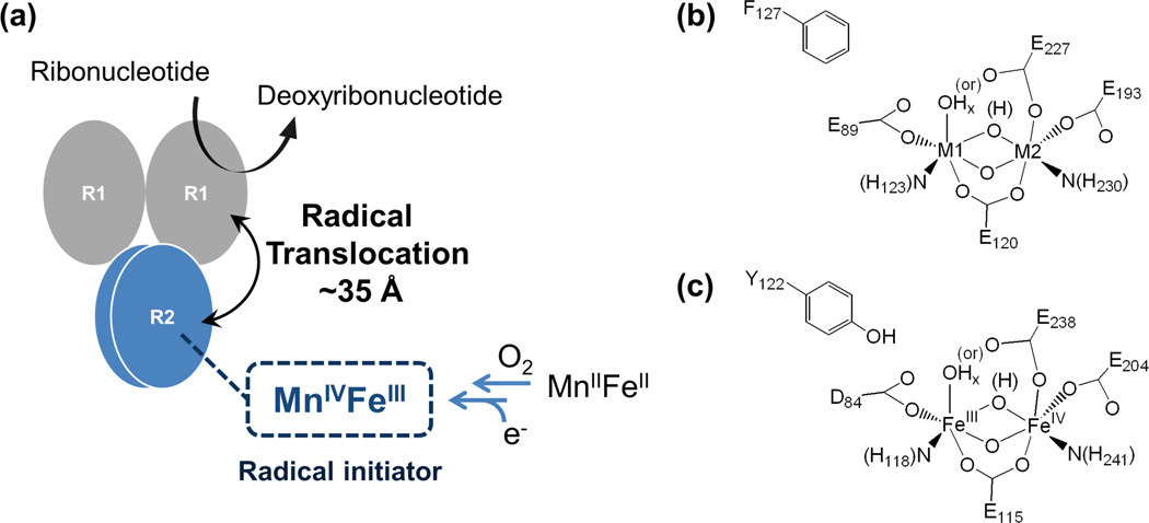
In the class Ia RNRs, the electron hole is generated by the high-valent intermediate X, which abstracts a hydrogen atom from a nearby tyrosine. This tyrosine radical then transfers its electron hole over ~35 Å by a series of hole-hopping and/or proton-coupled electron transfer (PCET) steps,4,5 ultimately leading to the initiation of substrate reduction by abstraction of the 3'-H. A number of structural studies on the intermediate X have been performed using Mössbauer, electron paramagnetic resonance (EPR), electron-nuclear double resonance (ENDOR), extended X-ray absorption fine structure (EXAFS), and magnetic circular dichroism (MCD) spectroscopies.6–18 Based on these studies, was shown to have an Fe IIIFeIV center that has strong antiferromagnetic coupling between two high-spin irons, giving an S=1/2 ground state reflecting a bridged structure with at least one oxo-bridge.9 The FeIV center is at the distal position to the tyrosine residue (Y122, scheme 1(c)),16,18 which is oxidized by X to produce a stable tyrosine radical. These studies have provided fundamental insight into the O2 reaction mechanism of the biferrous site and how the tyrosine radical (Y•) is generated. However, there is still an issue concerning whether one oxo bridge is protonated.16,17,19
Scheme 1.
(a) Function of the MnIVFeIII cofactor in catalysis by a class Ic ribonucleotide reductase: substrate reduction in α (R1) following radical initiation by MnIVFeIII cofactor in β (R2) through a radical-translocation process; (b) structure of the MnIVFeIII cofactor site in class Ic ribonucleotide reductase (x = 1 or 2, M1 = metal site 1, and M2 = metal site 2); and (c) structure of the FeIIIFeIV intermediate X in class Ia ribonucleotide reductase (x = 1 or 2).
In the class Ic RNRs, the position occupied by the tyrosine residue (Y122) in the class Ia (and Ib) orthologues is instead occupied by a phenylalanine (F127), which does not generate a radical.20 A number of studies have determined that in the class Ic RNRs, the metal center with the Mn IVFeIII redox state is directly responsible for the radical initiation.21–24 This oxidized cofactor is generated by the reaction of the Mn IIFeII site with O2 and proceeds through a MnIVFeIV intermediate that undergoes one-electron reduction (via a residue at the surface of the protein) to form the catalytically active Mn VFe site (scheme 1(a) and (b)).26 Mössbauer, EXAFS, and anomalous diffraction crystallography have been employed to study this cofactor site.22,27–29 This Mn IVFeIII center has an S=1 ground state from strong antiferromagnetic coupling between the Mn and Fe centers.22 A structure with oxo, hydroxo bridges was favored based on the atomic distances,27 and the Mn was observed in the metal site 1 (close to F127, scheme 1(b)).29,30 However, a range of questions still remains in terms of its geometric and electronic structure and how its electron-hole initiation and transport mechanistically relate to the analogous processes in the tyrosine-radical-dependent class Ia orthologs.
The goal of this study is to further define the geometric and electronic structure of the MnIV FeIII cofactor site in class Ic RNRs, which is important as a functional analog of the radical initiator Y• as well as a structural analog of the high-valent intermediate X in the class Ia enzymes. In this study, a suite of spectroscopic approaches, including absorption (Abs), circular dichroism (CD), magnetic CD (MCD), variable temperature, variable field (VTVH) MCD, and nuclear resonance vibrational spectroscopies (NRVS), has been used to define the geometric and electronic structure of the MnIV FeIII cofactor in Ct RNR. NRVS is a relatively new, 3rd generation synchrotron-based technique that measures the inelastic vibrational side bands of the 57Fe Mössbauer nuclear transition at 14.4 keV that involve Fe motion 31,32 and is therefore a direct probe of the Fe site. MCD focuses on ligand-field (LF) and charge transfer (CT) transitions.33 High MCD to Abs intensity is associated with spin-allowed LF transitions of the MnIV (as high-spin FeIII LF transitions are all spin-forbidden), which provide a direct probe of the Mn site, whereas the CT transitions probe the ligands bound to both the MnIv and the FeIII. Coupled with DFT calculations, this study defines the geometric and electronic structure fo the MnIV FeIII active site in Ct RNR and its correlation to the binuclear non-heme iron site in the class Ia enzymes.
Experimental section
1. Sample preparation
Samples of the MnIVFeIII complex of Ct RNR were prepared as previously described.22 The MCD samples were made by mixing the MnIVFeIII complex in buffer (100 mM HEPES, H2O or D2O) with glycerol (or glycerol-d3, 50% v/v for final concentration) as a glassing agent for low-temperature spectral measurements. Samples of the MnIVFeIII complex for NRVS were prepared with 57Fe, and the species present in the samples were quantified by Mössbauer spectroscopy. The samples were injected into custom-made cells and frozen in liquid N2.
2. Spectroscopic methods
The room-temperature Abs spectrum was measured on an Agilent 8453 UV-Visible (UV/Vis) Spectrophotometer. The low-temperature Abs spectrum was obtained by using a Cary 500 spectrophotometer with a Janis STVP-100 continuous-flow liquid helium (He) cryostat equipped with a Lakeshore model 332S temperature controller.
UV/Vis (300–900 nm region) CD and MCD data were collected on a Jasco J810 spectrometer with an extended S-20 photomultiplier tube, and near-infrared (NIR, 600–2000 nm region) CD and MCD data were collected on a Jasco J730 spectrometer with a liquid N2–cooled InSb detector. The MCD spectra were obtained at temperatures between 1.8 K and 50 K. The sample temperature was measured by using a calibrated Cernox resistor (Lakeshore Cryogenics) inserted into the MCD cell. Magnetic fields from 0 T to 7 T were applied by using an Oxford magnet (either SM 4–7T or SM 4000-7T). For each field and temperature, (+) and (−) signals were averaged for baseline correction and to improve the signal-to-noise (S/N) ratios. VTVH MCD data were normalized to the observed intensity at lowest temperature and highest field (1.8K, 7T) over all isotherms for a given wavelength. The VTVH MCD data were fit to extract values of the spin Hamiltonian, with the ground-state parameters given by the spin projection of the single metal site into the dimer wavefunctions (see ref 33).
NRVS spectra were collected at beam line BL09XU at SPring-8 in Hyogo, Japan and at beam line 3-ID-D at the Advanced Photon Source, Argonne, U. S. A. on multiple visits. Spectra were collected between −25 and 80 meV in 0.25 meV steps. During data collection, the samples were maintained at 20–30 K by using a liquid He cryostat. Photoreduction effects were evaluated by comparing successive spectra during data acquisition. Scans were averaged to obtain better S/N ratios. Averaged data were converted to partial-vibrational-density-of-states (PVDOS) spectra using the PHOENIX program.34
3. Computational methods
The starting geometry was obtained from the crystal structure of Fe-loaded Ct RNR R2 (1SYY RCSB structure).20 The protein active site residues were truncated by replacing the β-carbons with methyl groups. The positions of these β-carbons were fixed to impose the protein backbone constraints for the geometry optimization but not the frequency calculations. This allowed for the large number of calculations required and gave relative energies very similar to those obtained in calculations in which the α-carbons were constrained.35,36 Calculations were performed with the Gaussian 09 software package37 unless specified otherwise.
For NRVS spectral simulations, geometry optimizations and frequency calculations were performed using the spin-unrestricted BP86 functional with the LANL2DZ basis set. Previous studies on inorganic complexes have shown that this combination reproduced NRVS spectra for known structures.38–41 The vibrational modes were converted to NRVS partial-vibrational-density-of-states (PVDOS) spectra using the gennrvs program.38 These spectra were further validated with parallel- simulated spectra using heavy masses at the β-carbons and their hydrogens to limit the effect of protein backbone motion.
For LF and CT transitions, geometry optimizations and TD-DFT calculations were performed by using the spin-unrestricted B3LYP functional with the 6–311+g* basis set on the metals and 6–31g* on the rest of the atoms. This functional and basis set combination was calibrated by comparison to data on inorganic complexes, as described in section 2.4.1. Zero-field splitting (ZFS) parameter D and E were calculated for these optimized structures by using the Orca 2.8.0 program 42,43 with the B3LYP functional. The CP(PPP) basis set was used for the metals, and the TZVP basis set was used for the rest of the atoms.
Total energies of the different candidate structures were calculated with the spin-unrestricted B3LYP* functional (15% Hartree-Fock (HF) exchange rather than the conventional 20%) and the 6–311+g* basis set for the geometry-optimized structures (spin-unrestricted BP86 functional with LANL2DZ basis set) for comparison to previous calculations. The effects of the protein environment were included by using the polarizable continuum model (PCM) with a dielectric constant (ε) of 4.0. Calculations of exchange coupling constants were performed by using the Orca 2.8.0 program, with the spin-unrestricted BP functional and the def2-SVP basis set. Mössbauer parameters were calculated by using the Orca 2.8.0 program, with the spin-unrestricted BP functional. The CP(PPP) basis set was used for the metals, and DZP basis set was used for the rest of the atoms. The parameters obtained were corrected empirically on the basis of a correlation between theory and experiment.45
Results and Analyses
1. Nuclear Resonance Vibrational Spectroscopy (NRVS)
1.1 Spectrum
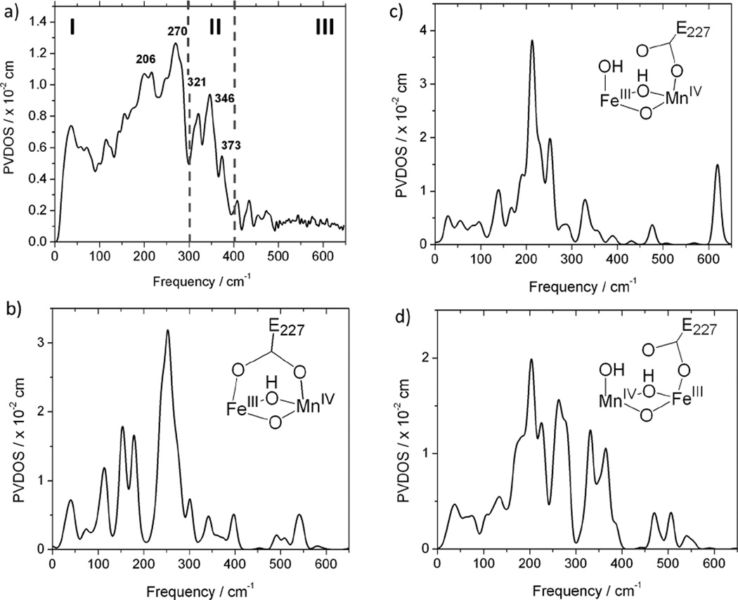
The PVDOS spectrum of the MnIVFeIII cofactor of Ct RNR-β (R2) is shown in Figure 1(a). This PVDOS intensity reflects the amount of Fe motion in a molecular vibrational mode at a given energy. On the basis of this selectivity and the correlation with structural variations described below, the experimental NRVS spectrum is divided into 3 regions: intense features in the low-energy (200–300 cm−1) region (region I), moderately intense features in the 300–400 cm−1 region (region II), and absence of features in the high-energy region above 400 cm−1 (region III). To obtain insight into the geometric structure of the complex, this experimental spectrum was compared to a series of NRVS spectra calculated by DFT for different possible structures (Section 1.2)
Figure 1.
(a) NRVS spectra of the MnIVFeIII cofactor; and representative simulations for structures having (b) two carboxylate bridges (bridging E227); (c) one carboxylate bridge (terminal E227) with FeIII at site 1; and (d) one carboxylate bridge (terminal E227) with MnIV at site 1.
1.2 DFT calculations and spectral simulations
In past studies on structurally defined model complexes, the NRVS spectra calculated from DFT-optimized structures correlated well with the experimental NRVS spectra, indicating that NRVS is a powerful technique for defining geometric structure.38–41 To analyze the NRVS spectra, DFT calculations were performed for 18 different possible structural models of the MnIVFeIII cofactor in Ct RNR-β (R2). It was assumed that this cofactor has some structural similarity to the FeIIIFeIV intermediate, X, in E. coli RNR-β (R2), and 4 different structural variations were therefore evaluated: 1) one vs. two carboxylate bridges (i.e., terminal bound E227 on metal site 2 vs. µ-1,3 E227 residue), 2) Mn or Fe at metal site 1, which is the metal site proximal to F127 that replaces Y122• of the class Ia RNR-β (R2) protein from E. coli (scheme 1(b)), 3) bis(µ-oxo) vs. µ-oxo, µ-hydroxo core, and 4) for the structures with a single carboxylate bridged structure (i.e., terminal E227 residue at metal site 2), either a terminal water or a hydroxo ligand at metal site 1.
The simulated NRVS spectra for 18 different structures are shown in Figure S3, which are represented by the NRVS spectra shown in Figure 1(b)–(d). Comparison of simulated spectra to the experimental spectrum in Figure 1 (a) provides systematic structural insight. For the structures with two carboxylate bridges, the calculated NRVS spectra show very little NRVS intensity in region II (300–400 cm−1) as represented in Figure 1 (b), regardless of which metal is at site 1 of the core bridging structure (first column of Figure S3). Thus, the presence of the features in region II in the experimental spectrum in Figure 1 (a) requires that the complex possess at most one, and not two, bridging carboxylate ligands. In the cases of single carboxylate bridged structures, the calculated NRVS spectra are very sensitive to the metal (Mn or Fe) at site 1, as shown in Figure 1(c) and Figure 1 (d). For the single-carboxylate bridged structures with Fe at site 1, intense features are calculated to be present in region III (400–600 cm−1), as shown in Figure 1 (c), which are absent in the experimental data. While these features in region III are less intense for the structures with a terminal water ligand on an Fe at site 1, this leads to features in region I at energies below 240 cm−1, which do not correlate with the experimental data (supporting Figure S3, second column). Thus the NRVS intensities in region III and in region I below 240cm−1 together, as shown in Figure 1 (a) vs. 1(c), rule out all single carboxylate bridged structures with Fe at site 1. For the single-carboxylate bridged structure with Mn at site 1, as shown in Figure 1 (d), the calculated spectrum agrees well with the experimental NRVS spectrum, having intense features in region I and moderately intense features in region II. For these structures, the high-energy features are calculated to be weak (totaling less than 10% of the NRVS intensity distributed over region III) and do not to contribute to the NRVS spectrum above the noise level. Therefore, comparisons of the calculated to the experimental spectrum indicate that the MnIVFeIII complex has a single carboxylate bridge (a terminal carboxylate E227 on Fe at site 2) and Mn at site 1. These structures could have either a bis(µ-oxo) or µ-oxo, µ-hydroxo core and either a terminal hydroxo or water on the Mn.
While the calculated NRVS spectra are not very diagnostic of the core bridging structure (bis(µ-oxo) vs. µ-oxo, µ-hydroxo) or the nature of the terminal ligand (OH− vs. H2O) on Mn at site 1, further analyses of these models limit the structural possibilities. The bis(µ-oxo) core structure with a terminal OH− ligand on the Mn at site 1 significantly lowers the intensity in region II (300–400 cm−1) as compared to the experimental NRVS spectrum, due to the poor linkage between the Mn and Fe sites (the short Mn-µ-oxo and Mn-terminal OH bonds prevent mixing of Fe motion into the Mn motion), and therefore can be ruled out (Figure S3, right column top spectrum). In addition, among the structures with a µ-oxo, µ-hydroxo core, structures with the hydroxo bridge on the side of the Mn/Fe core with the two His ligands (Figure S3, right column 5th and 6th spectra from the top) were at higher energy (by 4–9 kcal/mol) compared with structures with the hydroxo bridge on the side of the Mn/Fe core with 2 carboxylate ligands (Figure S3, right column 3rd and 4th spectra from the top), consistent with previous computational results.44 Therefore, of the six possible structures with a single carboxylate bridge and Mn at site 1, three structures remain viable: a bis(µ-oxo) core with a terminal H2O ligand, a µ-oxo, µ-hydroxo core with a terminal H2O ligand, and a µ-oxo, µ-hydroxo core with terminal OH− ligand.
1.3 Spectral assignments
The previous section narrows the possible structural models for the MnIVFeIII cofactor to 3 out of the 18 originally considered (Figure S3, right column, 2nd–4th spectra from the top). These 3 remaining structures give similar normal modes with Fe displacements at similar energies. Here, we assign and describe the modes contributing to each region by consideration of the structure with µ-oxo, µ-hydroxo core and terminal OH on the Mn (Figure 2), which is supported by the MCD results in the next section.
Figure 2.
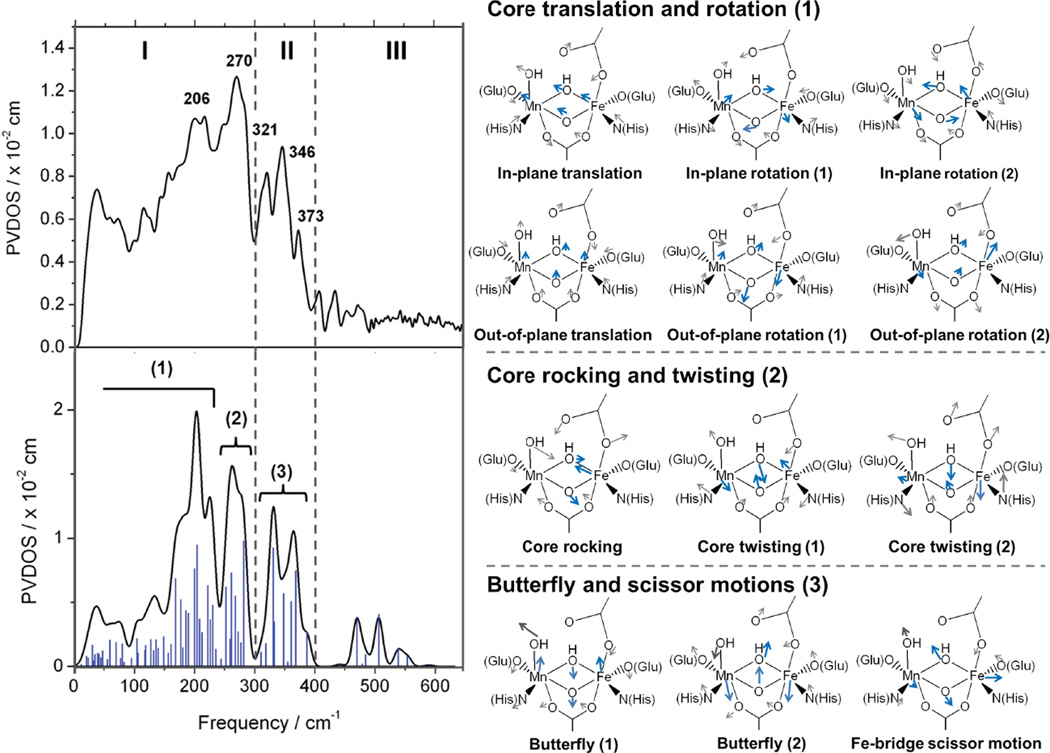
(Left) Spectra obtained from NRVS (experimental, top; simulated, bottom) and (Right) related core motions contributing to the features in the simulated spectrum.
In the low-energy region up to ~300 cm−1 (region I), the normal modes involve two types of motions: core translations and rotations (the Mn-(µ-O/µ-OH)-Fe core moving in the protein pocket, Figure 2, right (1)), and core rocking (Fe moving along the µ-O bridge and bridging atoms moving in the opposite direction) and twisting motions (pairs of metal-µ-O(H) moving in opposite directions, Figure 2, right (2)). For the 300–400 cm−1 region (region II), the features in the NRVS spectrum are mainly attributable to the butterfly motion (metals moving out of the plane with bridging O (and OH) moving in the opposite direction, Figure 2, right (3)), with a contribution from the Fe scissor motion (Fe moving along the metal-metal vector with the bridges moving out of the plane, in the perpendicular direction, Figure 2, right (3)). High-energy features in region III (> 400cm ) would arise primarily from metal-ligand (OH− or H2O) stretching motions for the metal in site 1 having the terminal OH− or H2O ligand. These have very low intensity when Mn is at site 1 with a single carboxylate bridge, because the Mn-terminal OHx stretch involves little Fe motion. This consideration explains the absence of features in region III in the experimental data in Figure 2 (a).
2. Abs/CD/MCD spectroscopy
2.1 Spectra
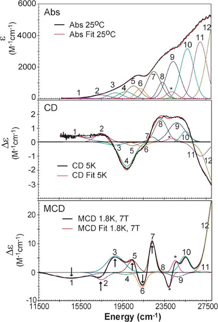
Abs, low-temperature CD and MCD spectra for the Mn IVFeIII complex of Ct RNR-β (R2) are shown in Figure 3. The sample contained ~13–15 % FeIIIFeIII and ~7–10 % MnIIIFeIII component, as determined by analysis of the Mössbauer spectrum of a sample prepared in parallel with the NRVS sample (Figure S1, S2, and Table S1). The contributions of these components to the spectra are negligible in comparison with those from the predominant MnIVFeIII species (spectra for the pure FeIIIFeIII form are shown in Figure S6). A simultaneous Gaussian fit of the spectra in Figure 3 requires at least 12 bands in the range from 11,500 cm−1 to 28,000 cm−1 [note that there is a small contribution from a heme contaminant (*)]. These bands are assigned on the basis of their energies and their C0/D0 (MCD to Abs) intensity ratios. Because all d-d transitions are spin forbidden in a high-spin d5 FeIII site, any d-d transition with significant intensity in these spectra must involve the MnIV , as these transitions are spin-allowed. (A forbidden “spin-flip” transition for the d5FeIII would be distinguished by its narrow bandwidth as there is no change in orbital occupancy). The C0/D0 ratio is given by
| (1) |
where kB is the Boltzmann constant, µB is the Bohr magneton (kB/µB= 1.489 K−1 T), T is the temperature in K, ε is the molar absorptivity in M−1 cm−1, and Δε is the MCD intensity maximum in M−1 cm−1 T−1 recorded in the linear 1/T region. Features in the MCD spectra (Figure 3) exhibit approximately the same total intensity in left (positive) and right (negative) circular polarization, and therefore the data obey the sum rule. In this case, MCD intensity derives from spin-orbit coupling (SOC) between excited states (vide infra). Because the SOC constant for MnIV is much larger (415 cm−1) than that of oxygen (60–70 cm−1 ) or nitrogen (50 cm−1) ligands,46,47 bands with high C0/D0 ratio have dominantly Mn character, which is the case for metal-centered LF transitions. Therefore, bands with high C0/D0 ratios must be MnIVd-d transitions, while bands with low C0/D0 can be assigned as ligand-to-metal CT (LMCT) transitions. From the C0/D0 ratios in Table 1, bands 1–4 are assigned as MnIVd-d transitions, while bands 5–12 are assigned as LMCT transitions. Because MnIV has a larger Zeff than FeIII,48–50 CT transitions to MnIV should contribute at lower energy than CT transitions to FeIII. However, a previous study on oxo-bridged FeIII dimers showed that a bent µ-oxo can give rise to an intense oxo-to-FeIII CT transition feature at ~ 19,000 cm−151, similar to the energy of the lowest-energy CT band (band 5) in Figure 3. Spectral assignments for the CT region are presented in section 2.4.
Figure 3.
Abs, CD and MCD spectra of the MnIVFeIII cofactor in Ct RNR-β (R2). The arrows indicate the energies where the VTVH data were collected, and the * indicates a minor heme contaminant in the sample.
Table 1.
Simultaneous Abs/CD/MCD peak fits
| Band | Abs |
CD |
MCD |
C0/D0 ratio |
assignment | ||||||
|---|---|---|---|---|---|---|---|---|---|---|---|
| Energy (cm−1) |
FWHM | Energy (cm−1) |
FWHM | sign | Energy (cm−1) |
FWHM | sign | ||||
| 1 | 14662 | 3663 | 14600 | 3205 | + | 14617 | 3206 | − | 0.0477 | d-d | MnIV |
| 2 | 17480 | 1967 | 17520 | 1460 | + | 17500 | 1319 | − | 0.0146 | d-d | |
| 3 | 18900 | 2003 | 18750 | 1883 | − | 18750 | 2002 | + | 0.0183 | d-d | |
| 4 | 19850 | 1650 | 19951 | 1649 | − | 19950 | 1648 | − | − | d-d | |
| 5 | 20594 | 1530 | 20480 | 1060 | − | 20500 | 1060 | + | 0.0074 | CT | MnIV or FeIII |
| 6 | 21307 | 1177 | 21380 | 1166 | − | 21380 | 1168 | − | 0.0038 | CT | |
| 7 | 22540 | 1401 | 22355 | 871 | + | 22300 | 824 | + | 0.0091 | CT | |
| 8 | 23400 | 1377 | 23195 | 1413 | + | 23200 | 1402 | + | 0.0002 | CT | |
| 9 | 24490 | 1796 | 24700 | 1342 | + | 24700 | 1177 | − | 0.0018 | CT | |
| 10 | 25725 | 1483 | 25535 | 1012 | + | 25500 | 1043 | + | 0.0028 | CT | |
| 11 | 26959 | 1471 | 26917 | 1451 | − | 27000 | 1440 | + | 0.0001 | CT | |
| 12 | 28354 | 1732 | 28604 | 2066 | − | 28393 | 1610 | + | 0.0080 | CT | |
2.2 VTVH MCD
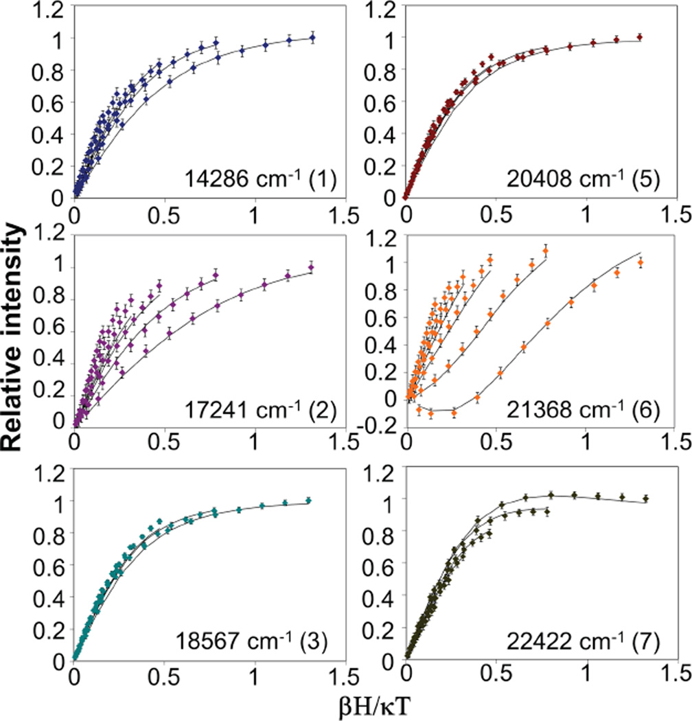
The ground-state spin-Hamiltonian parameters of the active site and the polarizations of each transition were obtained from VTVH MCD data. VTVH data were collected for different bands at the energies indicated by arrows in Figure 3 (MCD). VVH data above 23,000 cm−1 could not be collected due to the decomposition of the cofactor induced by the high-energy photons (even at the low intensity exiting the monochromator). MCD saturation data were collected for the six bands at a series of temperatures with a range of fields and are plotted as relative intensity vs. βH/kBT in Figure 4. The VTVH data were collected near the Gaussian maxima but at energies selected to minimize contributions from overlapping bands. For band 2, the contribution from band 3 was subtracted, as it has significant overlap. Bands 3 and 5 showed the same behavior, while all other bands exhibited different behaviors.
Figure 4.
VTVH data for different bands, as indicated in Figure 3. Fits producing |D| = 2.3 cm−1E/D = 0.33 are shown as black lines.
These VTVH MCD data were fit using a spin-projection approach. This model correlates MCD intensity with the polarizations of transitions on the basis of the spin-expectation values of each of the sublevels in the dimer spin system. The relevant relation is52
| (2) |
In equation (2), x, y, and z refer to the principal axes of the ground-state spin Hamiltonian (vide infra); θ and φ are the polar angles between the incident light and the molecular z-axis; lx, ly, and lz are the direction cosines for the magnetic field relative to the molecular coordinate system; are the products of the polarizations of the electronic transitions; and γ is a collection of constants. This equation is also dependent on Ni, the Boltzmann population, and 〈Sp〉i, the spin expectation value in the p direction for the spin sublevel i of the ground state. Two perpendicular transition moments, j and k, are required for MCD intensity. In a low-symmetry protein site, these transitions are unidirectional, so a non-zero value is achieved by spin-orbit mixing with another excited state that has a perpendicularly-polarized transition moment.
The MnIVFeIII cofactor has a ground state of Stot = 1 derived from antiferromagnetic coupling of MnIV (S = 3/2) with Fe (S = 5/2)22 An S tot = 1 system has Ms = 0 and ± 1 sublevels, which are split by the axial zero-field splitting (ZFS, D). The Ms = +1 and −1 are split by rhombic splitting (E).
A series of D and E/D values were evaluated. The best-fit spin-Hamiltonian parameters are |D| = ~2.3 (± 0.4) cm−1 and | E/D| = 0.33 (Figure 4). These values agree well with those determined independently from Mössbauer spectroscopy.22 The effective transition moment products Meff were also obtained for each band. The percent polarization along each direction of the ZFS tensor for each transition can be determined from equation (3) 52 (%y, %z obtained by cyclic permutations of the indices.)
| (3) |
These polarization directions depend on the signs of D and E/D. However, regardless of the signs, the fits to the bands 5, 6 and 7 require three mutually-perpendicular polarizations. In section 2.4, the signs of D and E are both determined to be negative. The polarizations obtained for the different transitions with D = −2.3 cm and E/D = 0.33 are given in Table 2.
Table 2.
Effective transition moments and percent polarization for VTVH data of the MnIVFeIII cofactor
| band | Mxy | Mxz | Myz | %x | %y | %z |
|---|---|---|---|---|---|---|
| 1 | 0.44 | 1.13 | 0.50 | 40.2 | 7.9 | 51.9 |
| 2 | 0.45 | 2.30 | −0.55 | 39.2 | 2.2 | 58.6 |
| 3 & 5 | 1.19 | 0.94 | −0.25 | 89.7 | 6.3 | 4.0 |
| 6 | −0.61 | 6.05 | −2.23 | 6.9 | 0.9 | 92.2 |
| 7 | 1.14 | −0.84 | 1.33 | 20.5 | 51.5 | 28.0 |
2.3 Ligand-Field (LF) analysis
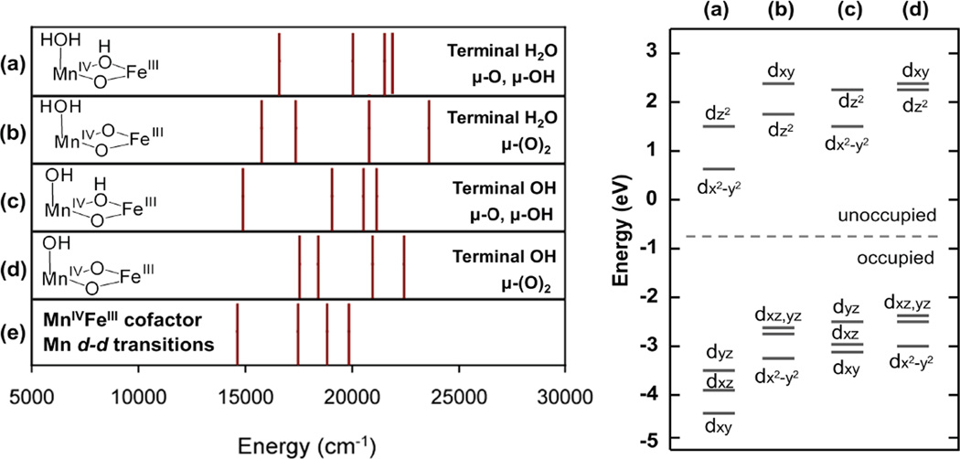
As presented in section 1, the NRVS spectrum clearly requires the MnIV ion to be bound at site 1 (close to F127). Allowing for different bridging (bis(µ-oxo) vs. µ-oxo, µ-hydroxo) and protonation states of the site 1 solvent ligand (H2O vs. OH ), 4 structural models or the MnIVFeIII cofactor was considered (note of these structures the one with a bis(µ-oxo) core and a terminal OH− was also inconsistent with the NRVS data; see section 1.2).the MnIV LF transition energies or these models were calculated by TD-DFT (see Figure S7 (c)) and compared to the experimental LF transition energies for bands 1–4 assigned in section 2.1. From the experimental energies in Figure 5 (e), the lowest-energy MnIVd-d transitions show a pattern in which bands 1 and 2 are split by ~ 3000 cm−1 and band 2 and 3 are split by ~1500 cm−1 The calculated LF transitions for the 4 possible structural models from section 1 are compared to the experimental splitting in Figure 5. The experimental pattern is consistent only with the µ-oxo, µ-hydroxo core structures for which these d-d transitions are calculated to have 3000–4000 cm−1 (band 1 and 2) and 1000–1500 cm−1 (band 2 and 3) splittings regardless of whether there is a terminal H2O or OH− ligand at the open coordination position at site 1. For structures with bis(µ-oxo) cores, the calculated LF transitions have the opposite splitting pattern, with transitions 1 and 2 split by less than 1500 cm−1, and bands 2 and 3 split by ~3000 cm−1. Therefore, bis(µ-oxo) core structures can be ruled out for the MnIVFeIII cofactor, consistent with the conclusion reached in a previous EXAFS and DFT study that the Mn-Fe distance of 2.9 Å is too long for a complex with two µ-oxo ligands.27 This difference reflects the µ-oxo orbital mixing into the occupied Mn dπ orbitals. The structures with the oxo, hydroxo bridges have significant oxo-π out-of-plane orbital mixing into the Mn dyz orbital from π overlap, only moderate oxo-π in-plane mixing into the dxz orbital (because this in-plane orbital acquires some σ-character in the bent structure), and no oxo-π mixing into the dxy orbital (z along the Mn-µ-oxo bond and y perpendicular to the bent Mn-O-Fe plane). These interactions split the energies of the occupied d orbitals and result in the large difference in the energies of transitions 1 (dyz → dx2-y2) and 2 (dxz→dx2-y2). In contrast, the structures with bis(µ-oxo) cores would have significant oxo-π out-of-plane mixing into both the dxz and dyz orbitals and less in-plane oxo-π mixing into dx2-y2 (z perpendicular to the M2O2 plane, x along Mn-Fe). This pattern would increases the energies of both the dxz and dyz occupied orbitals relative to dx2-y2 and result in a small calculated splitting between transitions 1(dyz→ dz2) and 2 (dxz→ dz2) (Figure 5, right).
Figure 5.
(Left) Comparison of the energies of the calculated d-d transitions (from TD-DFT) for four different structural models of the MnIVFeIII cofactor (a–d) and the experimental d-d transitions from MCD spectra, and (Right) relative MnIV d orbital energies for each structural model.
2.4 Charge Transfer analyses
2.4.1 TD DFT calculations
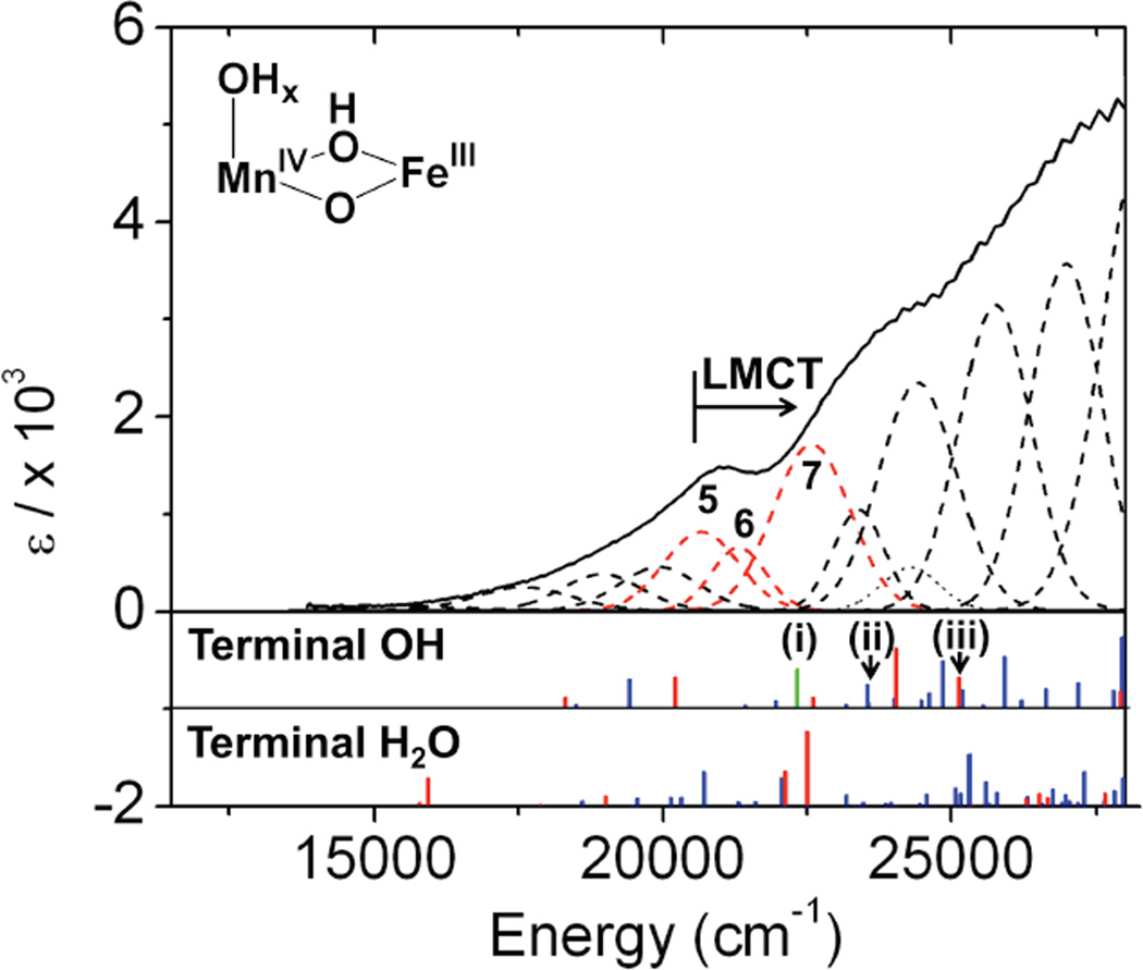
From the previous section, the Mn IVFeIII active site is defined to have a µ-oxo, µ-hydroxo, (mono)-µ-carboxylato core structure. TD-DFT calculations were performed for the two remaining possible structures with this geometry (terminal OH− vs H2O on MnIV ), and the LMCT transitions obtained were compared to the experimentally observed CT transitions. To obtain realistic estimates of the transition energies for comparison to the experimental values, CT to MnIV was calibrated according to a bis(µ-oxo) MnIV MnIII model complex,53 and CT to FeIII was calibrated according to bis(µ-oxo) and µ-oxo, µ-hydroxo FeIIIFeIII complexes.54–56 For each calibration, the TD-DFT calculations reproduced the CT transitions for the associated model complex but with some shift in the energies. (Figures S7 and S8: for CT to MnIV the energy shift is –5000 cm−1; for CT to FeIII the shift is +1500 cm−1). In the calculations for the protein, for transitions localized on one metal site, the second metal site was replaced with GaIII. Therefore, transitions to MnIV were calculated for a structure in which the FeIII was substituted with GaIII (geometry optimization resulted in only minor structural changes). Transitions to the FeIII site were calculated for a structure in which the MnIV was changed to GaIII (in this case, without further optimization to avoid structural changes due to the difference oxidation state - note that further optimization with GeIV in place of MnIV still led to significant structural changes). The calculated LMCT transitions (energy shifted according to the calibrations) are shown in the bottom plots of Figure 6. For both structures (i.e., µ-oxo, µ-hydroxo core with either a terminal OH− or water on Mn at site 1), the calculated CT bands have high intensities starting at ~20 000 cm−1, consistent with the experimental Abs spectrum.57 However, a noticeable difference is observed between the CT calculations for the two models. The model with terminal OH− ligand has a low-energy CT transition to the MnIV (Figure 6, green bar) while the model with terminal H2O does not. Therefore, the calculations show that a MnIVFeIII complex with a terminal OH− would have three types of LMCT transitions in the low energy region: µ-oxo → MnIV, terminal OH− → MnIV, and µ-oxo → FeIII, whereas a MnIVFeIII structure with a terminal water would have only µ-oxo → MnIV and FeIII CT transitions. In the following section, this information is used to interpret CT transitions 5–7 and distinguish between these two possible models for the MnIVFeIII cofactor.
Figure 6.
LMCT Abs spectra of MnIVFeIII RNR-β (the three lowest CT bands are labeled bands 5–7) correlated to TD-DFT calculated µ-oxo → MnIV (blue), terminal OH− → MnIV (green) and µ-oxo → FeIII (red) CT transitions for two possible structures, with either OH− or H2O as the terminal ligand on Mn at site 1. The orbitals for (i), (ii), (iii) transitions are shown in Figure 7 (vide infra).
2.4.2 Pseudo-A terms
In the MCD spectrum, bands 5, 6, and 7 show derivative shaped pseudo-A term behavior (Figure 3, bottom), and, from VTVH MCD fitting, they were determined to have three perpendicular polarizations (Table 2).
For a spin-allowed transition from an orbitally non-degenerate Stot = 1 ground state |A〉 to an excited state |J〉, the C0 term intensity is given by52
| (4) |
Here, gw is the effective g-value of the S = 1 ground state in the w-direction, and are the SOC matrix elements in the w-directions, and is the component of the transition dipole moment between |A〉 and |J〉 in the u-direction (equivalent definitions for , and
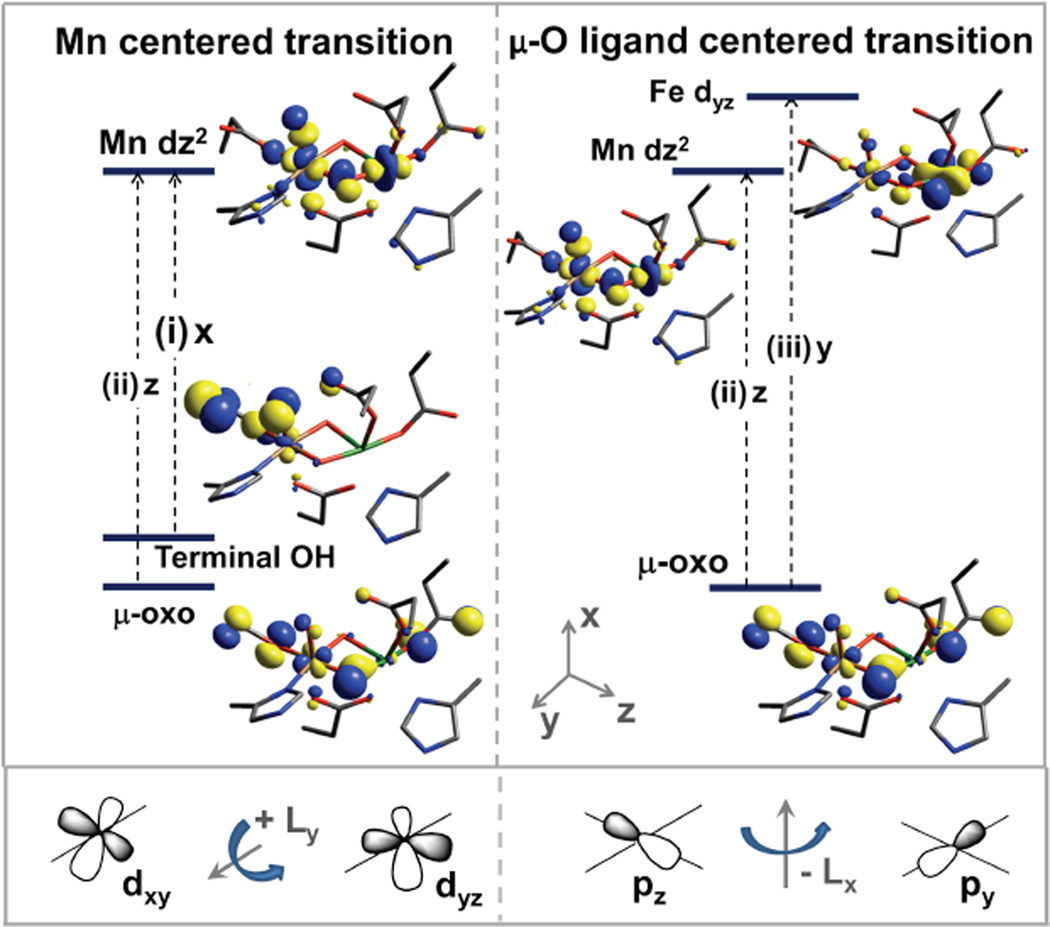
For a uni-directional |A〉 →|J〉 transition, a non-zero C0 value requires SOC between two excited states |J〉 and |K〉 of similar energies to which orthogonal polarized transitions are made from the ground state |A〉 The resultant MCD features from this mechanism obey the sum rule (equal intensities in both circular polarizations) and show a derivative signal pattern (This is expressed by the 1st term of the equation (4)). This mechanism involves SOC along the 3rd mutually orthogonal direction, which can involve metal-centered SOC (from different ligands to one metal site) or ligand-centered SOC (from one ligand to two metal centers). In Table 2, there are 3 perpendicular CT-transition polarizations for bands 5 –7, which also show pseudo-A term MCD behavior in Figure 3. This fact implies that there must be 2 sets of SOC among orthogonal transitions. These couplings can be between metal-centered oxo → MnIV and terminal OH−→ MnIV CT or between ligand-centered oxo → MnIV and oxo → FeIII CT transitions. The MnIVFeIII cluster will have three perpendicular polarizations only with a terminal OH− on the MnIV site. Therefore, the MnIVFeIII active site is defined as having a single bridging carboxylate, MnIV in site 1, µ-oxo, µ-hydroxo core, and a terminal OH on the MnIV ion.
Because MnIV has a larger Zeff than FeIII, the two lowest-energy transitions (band 5 and 6) should likely be assigned as terminal OH−→ MnIV and bridging oxo → Mn CT. Band 7 would then be assigned as the bridging oxo → Fe III CT transition. From TD-DFT calculations, a possible assignment for bands 5, 6, and 7 involving the pseudo-A intensity mechanism in eq (4) is given in Figure 7. Finally, these assignments are also suggested by the polarizations of the LF bands (bands 1–3, in Figure 3) obtained from the VTVH MCD analysis (Table 2). As d-d transitions borrow intensity from CT transitions and are MnIV -centered, the polarizations for bands 1–3 should reflect the polarizations of the CT to the MnIV. From Table 2, bands 1–3 are x- and z-polarized, corresponding to the polarizations fo transitions 5 (x-polarized) and 6 (z-polarized). They can thereby be assigned as terminal OH− and µ-oxo to MnIV CT transitions.
Figure 7.
LMCT processes associated with pseudo-A term features. For pseudo-A term MCD behavior, there must be 2 perpendicular CT transitions and SOC along a 3rd mutually-orthogonal direction. SOC is a single center 1e− operator. Therefore, 2 CTs must be “from” the same orbital or “to” the same orbital. Among the CT transitions in the TD-DFT calculations, there are 3 transitions (i, ii, iii) involving orbitals which could SOC via a 3rd perpendicular direction. For Mn-centered transitions, the terminal OH− → Mn CT transition is x-polarized, and the µ-oxo → Mn CT transition is z-polarized. The ligand donor orbitals are mixed with dxy and dyz, which SOC via Ly (bottom left). For µ-oxo ligand-centered transitions, the CT to Mn is z-polarized and the transition to Fe is y-polarized. These metal d orbitals are mixed with the Opz and Opy ligand orbitals, which SOC via Lx (bottom right)
2.4.3 ZFS tensor and polarizations
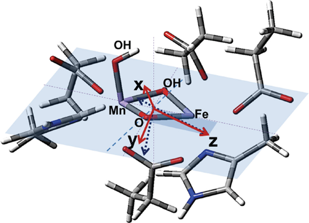
CT transitions are polarized along the specific ligand-metal bond involved in the CT process, whereas the polarization directions determined by VTVH MCD are defined by the axes of the ZFS tensor. The coordinate frame of the ZFS tensor was calculated from the geometry-optimized structure with MnIV at site 1, a terminal carboxylate E227 on Fe site 2, OH− on the Mn, and µ-oxo/µ-OH core. This coordinate frame was then compared to the polarizations derived from VTVH MCD. The ZFS tensor for this binuclear site was calculated using58
| (5) |
by re-diagonalizing the combined ZFS matrix obtained for each metal center. The resultant tensor of the dimer is mostly governed by the ZFS of the FeIII site. The strong contribution from the FeIII is consistent with the rhombic behavior obtained from the fitting of the VTVH MCD and Mössbauer data,22 as the FeIII center does not have a dominant, axial direction owing to the stronger bonding of the µ-oxo bridge to the MnIV ion. The orientations of the principal directions of the ZFS are shown in Figure 8 (blue dotted vectors). The bridging oxygen atoms are butterflied ~10° out of the Mn-(µ-O, µ-OH)-Fe plane. The bond between the terminal OH− ligand and Mn is almost perpendicular to the Mn-(µ-O, µ-OH)-Fe plane. The z-axis of the ZFS tensor is in the Mn-(µ-O, µ-OH)-Fe plane, tilted 12° from the Mn-Fe vector, in the direction of the Mn-oxo bond. The x- and y- axes are rotated +30 ° and −60 °, respectively, out of the Mn-(µ-O, µ-OH)-Fe plane (Figure 8). The Mn-ligand bonds have the following projections on this ZFS tensor: Mn-(µ-oxo): 81% z, 5% x and 14% y; Mn-OH: 25 % x and 75% y; Fe-(µ-oxo): 45% z, 41% x and 14% y. The projection of the Mn-(µ-oxo) bond is consistent with the description of band 6, as z-polarized and its assignment as a µ-oxo → MnIV CT transition. Conversely, the terminal OH−→ MnIV and µ-oxo → FeIII CT transitions have different projected polarizations relative to the experiment for bands 5 and 7. However, this structure should lead to an antisymmetric exchange contribution to the ZFS tensor, arising from the absence of inversion symmetry in the heterobimetallic center. This antisymmetric exchange interaction should be on the order of ~1 cm−1 (~(Δg/g)J)59,60 and in the direction perpendicular to the Mn-(µ-O, µ-OH)-Fe plane. This would rotate the x and y directions that have large out-of-plane components (Figure 8, solid vectors). Therefore, the projection of the OH− → MnIV CT would increase in x-polarization, and the projection of the µ-oxo → FeIII CT would increase in y-polarization, leading to the assignments of their associated CT transitions as bands 5 and 7, respectively.
Figure 8.
Calculated ZFS tensor orientation and intensity for the MnIVFeIII cofactor. Initial ZFS orientation is shown with blue dotted arrows, where x and y orientations rotate to red arrows due to the antisymmetric ZFS arising from hetero-bimetallic center.
3. H-atom abstraction energies and proton affinities
To evaluate the contributions of the MnIV position and the nature of the terminal ligand to the MnIVFeIII cofactor site reactivity, the energies of H-atom abstraction reactions were calculated for the different possible structural models. Table 3 gives H-atom (H+, e−) abstraction energies (all energies used the B3LYP* functional for correlation to previous calculations)44 for the class Ia Tyr and diiron centers, and the class Ic center with Mn at site 1 or 2 and either the OH− or H2O at the open site 1.
Table 3.
Comparison of calculated H-atom abstraction thermodynamic energies for different MnIVFeIII structures.
| Reaction (H+, e−) | Energy(1) (kcal/mol) |
|
|---|---|---|
| Calc. (Exp.)64 |
||
| a. |  |
−85.6 (−88.7 ± 0.6) |
| b. |  |
− 102.1 |
| c. |  |
−83.1 |
| d. |  |
−83.3 |
| e. |  |
− 82.5 |
| f. |  |
− 90.3 |
energy corrected for H· atom energy with same functional and basis set (313.7 kcal/mol)
The H-atom abstraction energy for the FeIIIFeIV complex, X, (Table 3, b) is larger by 12–20 kcal/mol than the H-atom abstraction energy for the Tyr and the four reactions of the MnIVFeIII cofactor (a, c-f). The H-atom abstraction energy of Y• (a; −85.6 kcal/mol) was calculated to be similar to those of three of the MnIVFeIII structures (c, d, and e; −83.1, −83.3, and −82.5 kcal/mol, respectively). However, when OH− is the terminal ligand at site 1, in contrast to the results of the earlier computational study, the position of the MnIV is found to have an impact, as the FeIIIMnIV structure (f) has a 7.8 kcal/mol greater H-atom abstraction energy than the MnIVFeIII structure (e).
To evaluate the selection of the µ-oxo/µ-hydroxo core structure over that with a bis(µ-oxo) core as the functioning model for the Ct RNR cofactor, the proton affinities of the four structures were evaluated with MnIV at site 1 and either an OH− or H2O ligand at this open site. The differences in the proton affinities of structures (1) and (2) and structures (3) and (4) in Table 4 are about 35 kcal/mol, mostly deriving from the charge difference between the pairs of sites. Thus the proton affinities for (2) and (3), where a proton is shifted from the bridge to the terminal hydroxide, are essentially the same.
Table 4.
Relative proton affinities among structures with MnIV at site 1
| Reaction (H+) | ΔΔE (kcal/mol) |
|
|---|---|---|
| (1) |  |
−35.9 |
| (2) |  |
0 |
| (3) |  |
−1.2 |
| (4) |  |
33.9 |
These computational results are considered below in terms of the contribution of the MnIVFeIII active site structure derived from NRVS/MCD spectroscopic studies to enzyme reactivity and its relevance to the class Ia radical-translocation mechanism.
Discussion
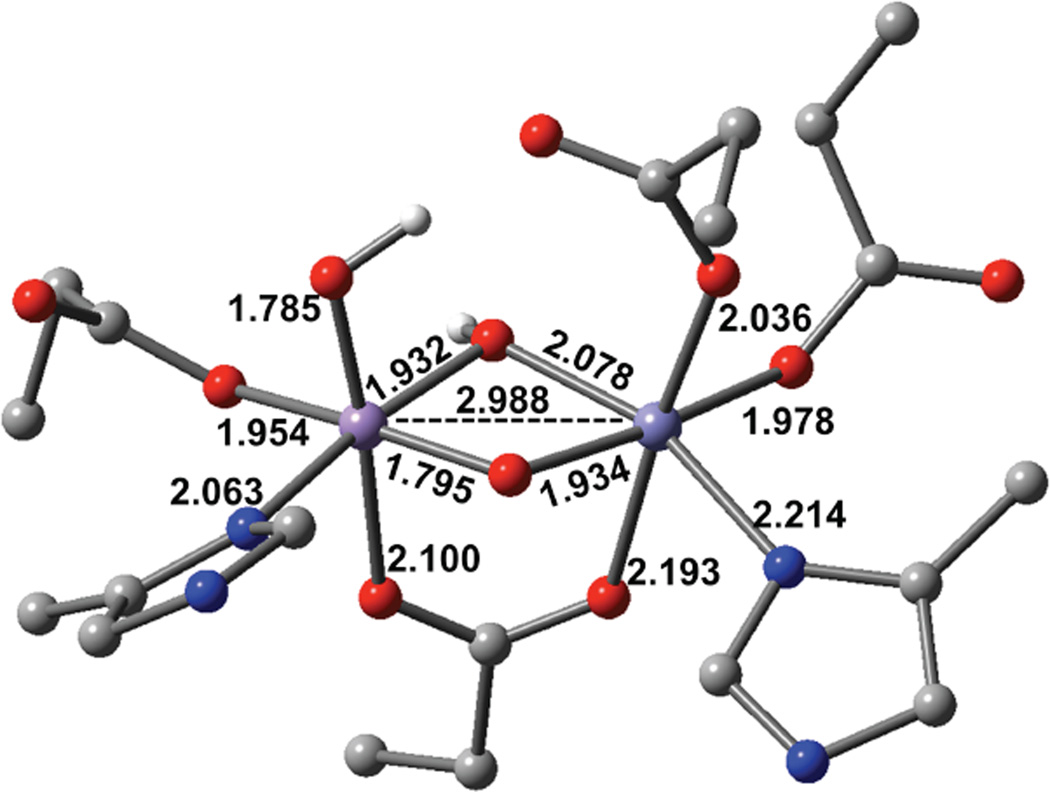
We have considered 18 possible structures for the MnIVFeIII cofactor and used the combination of NRVS and Abs/CD/MCD/VTVH MCD spectroscopies and DFT calculations to define its geometric and electronic structure. The NRVS spectrum (Figure 1 (a)) reflects the amount of Fe motion in the active site vibrations and exhibits a good correlation to the calculated spectra only when there is a single carboxylate bridge and Mn is at site 1. This Mn position is consistent with the results of recent x-ray crystallographic studies employing anomalous diffraction measurements.28–30 The terminal carboxylate, E227, at Fe in site 2 provides an open coordination position at the MnIV in site 1 for solvent coordination. The Abs/CD/MCD/VTVH MCD spectra are dominated by the spin-allowed LF transitions, which are present only for Mn IV, and the CT transitions that are able to produce MCD intensity through SOC. The LF energy-splitting pattern in Figure 5 (bands 1 to 4) requires a µ-oxo, µ-hydroxo core, and the pseudo-A term MCD behavior and polarizations of the CT bands (band 5–7, Figure 3 and 4, Table 2) indicate that the terminal ligand at the exchangeable position on the MnIV is hydroxo rather than water. These results and analyses lead to the optimized MnIVFeIII active site structure in Figure 9. It has 2 short Mn-O bonds from the µ-oxo and the terminal hydroxo ligand (~1.79 Å). This geometry correlates well with EXAFS data, which show 1 or 2 short Mn-O bonds at ~1.74 Å.27 The calculated Mn-Fe distance is 2.99 Å, where EXAF S found a Mn-Fe distance of 2.92 Å. The calculated exchange coupling is J = −97.3 cm−1 (−2JS1· S2 Hamiltonian) giving an Stot = 1 ground state (from antiferromagnetic coupling of MnIV (S= 3/2) and FeIII (S = 5/2)), consistent with Mössbauer spectroscopic results. The Mössbauer parameters calculated for this structure are δ = 0.63 and ΔEq = −1.56 mm/s (η = 0.33), which are in reasonable agreement with the experimental values o δ = 0.52 mm/s and ΔEq = −1.32 mm/s (η = 0.11).22,27 Therefore, the structure in Figure 9 is also consistent with existing spectroscopic data. These geometric and electronic structure of the MnIV eIII active site provide insight into its reactivity in radical translocation in the class Ic RNRs and its relation to the class Ia enzymes.
Figure 9.
DFT-optimized structural model for the MnIVFeIII cofactor from this study.
In class Ia RNRs, the FeIII FeIV intermediate X oxidizes the nearby tyrosine in the β (R2) subunit to generate the tyrosine radical that reversibly transfers its electron hole to the substrate site in the α (R1) subunit. However, in the class Ic Ct RNR, there is no nearby tyrosine in β (R2), and the MnIVFeIII active site itself plays the role of the Y• in electron hole transport. Therefore, the MnIVFeIII cofactor should have a free energy for uptake of a hydrogen atom equivalent or similar to that of the tyrosine radical in E. coli RNR-β (R2). This matching of thermodynamics is best accomplished by having a MnIV rather than an FeIV in its active site (Table 3, structure e vs. b), which depresses the H-atom abstraction energy to a value similar to that of the tyrosine radical (Table 3, a). This notion is consistent with the considerations in ref 44. However, unlike this earlier computational study,44 which used a terminal water ligand at the MnIV site and found similar reaction energies for MnIVFeIII and FeIIIMnIV structures (consistent with Table 3), the spectroscopic results presented here show that OH− is the terminal ligand at site 1. For this exogenous ligand at site 1, the FeIIIMnIV active site has a 7.8 kcal/mol greater energy for uptake of a hydrogen atom than the MnIVFeIII model. This depression of the energy for H• uptake in the favored structural model arises from the bonding of the strong terminal OH− donor to the MnIV, which stabilizes the MnIVFeIII reactant state to a greater extent than the corresponding FeIIIMnIV reactant state (with the terminal OH coordinated to the FeIII), bringing the free energy for H• uptake into alignment with that of the tyrosine radical (Table 3). An FeIIIMnIV active site would thus have reduced reversibility in transfer of the e− hole to the α (R1) subunit and thus poor reactivity, as observed experimentally.29 In addition, an FeIIIMnIV site would be more susceptible to irreversible reduction by an external electron donor, which would inactivate the enzyme.
Interestingly, the MnIVFeIII (and FeIIIMnIV) models with a terminal water at site 1 also have calculated H-atom abstraction energies similar to that of the Y• (Table 3, c and d vs a). However, the MnIVFeIII structure with a terminal water has ~34 kcal/mol lower proton affinity compared to that of the MnIVFeIII structure with terminal OH− (Table 4, (2) and (4)). If class Ic RNRs parallel the radical translocation reaction that occurs in class Ia RNRs, this difference in proton affinity would provide mechanistic insight into radical translocation in class Ic RNRs. In class Ia RNRs, the tyrosine radical transfers an electron hole to the α (R1) subunit, with the Y356 residue found to be involved in this process. Previous studies of class Ia RNRs suggested that a conformational change in the α (R1) subunit upon substrate binding induces proton transfer (PT) from the cofactor site to Y122• to initiate a PCET process.4,5 It was determined that the proton is transferred from the water ligand bound to the FeIII at site 1 to Y122•.61 In class Ic RNRs, the MnIVFeIII site replaces Y• and directly transfers an electron hole to the α(R1) subunit, and the equivalent protein residue to Y356 in class Ia RNRs, Y338, is also present and involved in the radical translocation process.62,63 Therefore, in class Ic RNR, α (R1) subunit and substrate binding could induce a conformational change leading to PT, in this case to the terminal OH− on the MnIV at site 1 to initiate the radical translocation process. From a comparison of the structures, the terminal carboxylate ligand E89 that replaces proton-transfer-mediating carboxylate D84 in the class Ia RNR-β (R2) subunits, could be involved in this conformational change. Alternatively, a structure with a terminal H2O at MnIV and a bis(µ-oxo) core, which would have a proton affinity similar to that of the structure in Figure 9 with a terminal OH− and µ-oxo/µ-OH− core (Table 4, (2) and (3)), would likely lack a mechanism to deliver the proton to the most basic site, the oxo bridge. Also, a structure with bis(µ-oxo) core and a terminal OH− (Table 4, (1)) might have too high a proton affinity to allow reversible allosteric regulation of proton transfer. However, it should be noted that at this point no spectroscopic evidence for the proton transfer in class Ic RNRs has been observed and thus substrate binding in the α (R1) subunit could induce a different conformational change in class Ic RNRs. Further spectroscopic studies on the effects of the α (R1) subunit and substrate binding on this cofactor site are required to understand the radical translocation mechanism in class Ic RNRs.
In conclusion, the combination of NRVS and optical (Abs/CD/MCD/VTVH MCD) spectroscopies with DFT calculations has afforded a detailed picture of the geometric and electronic structure of the MnIVFeIII active site in the class Ic Ct RNR. Comparison of the properties (reduction potentials and proton affinities) calculated for this spectroscopically elucidated structure and its possible structural isomers suggests that this structure is optimized for stability in the resting state and reversibility of its electron-hole generation in the α (R1) subunit to initiate catalysis.
Supplementary Material
Acknowledgements
Use of the Advanced Photon Source was supported by the Department of Energy, Office of Science, Contract DE-AC-02-06CH11357. Use of the synchrotron radiation at the BL09XU of SPring-8 was approved by JASRI (proposal no. 2010A1507 and 2010B1569). Financial support for this research was provided by grants from the NSF Biochemistry Program (MCB-0919027 to E.I.S.) and the National Institutes of Health (GM55365 to J.M.B. and C.K.), CREST, JST (to M.Seto), Alfred P. Sloan Minority Ph.D. Scholarship Program (to L.M.K.D), and a Samsung scholarship (to Y.K.)
Footnotes
Supporting Information
MnIVFeIII cofactor Mössbauer spectra used for NRVS and MCD study, calculated NRVS spectra for all 18 structural models, field- and temperature-dependent Abs (25 °C, 5 K), CD (25 °C, 5 K), and MCD spectra for the MnIVFeIII and FeIIIFeIII forms of Ct RNR-β (R2), calibration of the TD-DFT calculations (section 2.4.1), and the structure used for the TD-DFT calculations are provided. This material is available free of charge via the internet at http://pubs.acs.org
References
- 1.Jordan A, Reichard P. Annu. Rev. Biochem. 1998;67:71–98. doi: 10.1146/annurev.biochem.67.1.71. [DOI] [PubMed] [Google Scholar]
- 2.Stubbe J. Curr. Opin. Chem. Biol. 2003;7:183–188. doi: 10.1016/s1367-5931(03)00025-5. [DOI] [PubMed] [Google Scholar]
- 3.Nordlund P, Reichard P. Annu. Rev. Biochem. 2006;75:681–706. doi: 10.1146/annurev.biochem.75.103004.142443. [DOI] [PubMed] [Google Scholar]
- 4.Stubbe J, Nocera DG, Yee CS, Chang MCY. Chem. Rev. 2003;103:2167–2202. doi: 10.1021/cr020421u. [DOI] [PubMed] [Google Scholar]
- 5.Reece SY, Hodgkiss JM, Stubbe J, Nocera DG. Philos. Trans. R. Soc. Lond. B. Biol. Sci. 2006;361:1351–1364. doi: 10.1098/rstb.2006.1874. [DOI] [PMC free article] [PubMed] [Google Scholar]
- 6.Bollinger JM, Jr, Edmondson DE, Huynh BH, Filley J, Norton JR, Stubbe J. Science. 1991;253:292–298. doi: 10.1126/science.1650033. [DOI] [PubMed] [Google Scholar]
- 7.Bollinger JM, Jr, Tong WH, Ravi N, Huynh BH, Edmonson DE, Stubbe J. J. Am. Chem. Soc. 1994;116:8015–8023. [Google Scholar]
- 8.Ravi N, Bollinger JM, Jr, Huynh BH, Stubbe J, Edmondson DE. J. Am. Chem. Soc. 1994;116:8007–8014. [Google Scholar]
- 9.Sturgeon BE, Burdi D, Chen S, Huynh BH, Edmondson DE, Stubbe JA, Hoffman BM. J. Am. Chem. Soc. 1996;118:7551–7557. [Google Scholar]
- 10.Burdi D, Sturgeon BE, Tong WH, Stubbe JA, Hoffman BM. J. Am. Chem. Soc. 1996;118:281–282. [Google Scholar]
- 11.Willems JP, Lee HI, Burdi D, Doan PE, Stubbe JA, Hoffman BM. J. Am. Chem. Soc. 1997;119:9816–9824. [Google Scholar]
- 12.Burdi D, Willems J-P, Riggs-Gelasco P, Antholine WE, Stubbe J, Hoffman BM. J. Am. Chem. Soc. 1998;120:12910–12919. [Google Scholar]
- 13.Riggs-Gelasco PJ, Shu L, Chen S, Burdi D, Huynh BH, Que L, Jr, Stubbe J. J. Am. Chem. Soc. 1998;120:849–860. [Google Scholar]
- 14.Bar G, Bennati M, Nguyen H-HT, Ge J, Stubbe J, Griffin RG. J. Am. Chem. Soc. 2001;123:3569–3576. doi: 10.1021/ja003108n. [DOI] [PubMed] [Google Scholar]
- 15.Mitić N, Saleh L, Schenk G, Bollinger JM, Solomon EI. J. Am. Chem. Soc. 2003;125:11200–11201. doi: 10.1021/ja036556e. [DOI] [PubMed] [Google Scholar]
- 16.Mitić N, Clay MD, Saleh L, Bollinger JM, Solomon EI. J. Am. Chem. Soc. 2007;129:9049–9065. doi: 10.1021/ja070909i. [DOI] [PMC free article] [PubMed] [Google Scholar]
- 17.Shanmugam M, Doan PE, Lees NS, Stubbe J, Hoffman BM. J. Am. Chem. Soc. 2009;131:3370–3376. doi: 10.1021/ja809223s. [DOI] [PMC free article] [PubMed] [Google Scholar]
- 18.Bollinger JM, Chen S, Parkin SE, Mangravite LM, Ley BA, Edmondson DE, Huynh BH. J. Am. Chem. Soc. 1997;119:5976–5977. [Google Scholar]
- 19.Han W-G, Liu T, Lovell T, Noodleman L. J. Inorg. Biochem. 2006;100:771–779. doi: 10.1016/j.jinorgbio.2006.01.032. [DOI] [PubMed] [Google Scholar]
- 20.Högbom M, Stenmark P, Voevodskaya N, McClarty G, Gräslund A, Nordlund P. Science. 2004;305:245–248. doi: 10.1126/science.1098419. [DOI] [PubMed] [Google Scholar]
- 21.Jiang W, Yun D, Saleh L, Barr EW, Xing G, Hoffart LM, Maslak MA, Krebs C, Bollinger JM., Jr Science. 2007;316:1188–1191. doi: 10.1126/science.1141179. [DOI] [PubMed] [Google Scholar]
- 22.Jiang W, Bollinger JM, Jr, Krebs C. J. Am. Chem. Soc. 2007;129:7504–7505. doi: 10.1021/ja072528a. [DOI] [PMC free article] [PubMed] [Google Scholar]
- 23.Bollinger JM, Jr, Jiang W, Green MT, Krebs C. Curr. Opin. Struct. Biol. 2008;18:650–657. doi: 10.1016/j.sbi.2008.11.007. [DOI] [PubMed] [Google Scholar]
- 24.Jiang W, Yun D, Saleh L, Bollinger JM, Jr, Krebs C. Biochemistry. 2008;47:13736–13744. doi: 10.1021/bi8017625. [DOI] [PMC free article] [PubMed] [Google Scholar]
- 25.Jiang W, Saleh L, Barr EW, Xie J, Gardner MM, Krebs C, Bollinger JM., Jr Biochemistry. 2008;47:8477–8484. doi: 10.1021/bi800881m. [DOI] [PMC free article] [PubMed] [Google Scholar]
- 26.Jiang W, Hoffart LM, Krebs C, Bollinger JM., Jr Biochemistry. 2007;46:8709–8716. doi: 10.1021/bi700906g. [DOI] [PMC free article] [PubMed] [Google Scholar]
- 27.Younker JM, Krest CM, Jiang W, Krebs C, Bollinger JM, Jr, Green MT. J. Am. Chem. Soc. 2008;130:15022–15027. doi: 10.1021/ja804365e. [DOI] [PMC free article] [PubMed] [Google Scholar]
- 28.Andersson CS, Öhrström M, Popović-Bijelić A, Gräslund A, Stenmark P, Högbom M. J. Am. Chem. Soc. 2012;134:123–125. doi: 10.1021/ja209678x. [DOI] [PubMed] [Google Scholar]
- 29.Dassama LMK, Boal AK, Krebs C, Rosenzweig AC, Bollinger JM., Jr J. Am. Chem. Soc. 2012;134:2520–2523. doi: 10.1021/ja211314p. [DOI] [PMC free article] [PubMed] [Google Scholar]
- 30.Dassama LMK, Krebs C, Bollinger JM, Jr, Rosenzweig AC, Boal AK. Biochemistry. 2013;52:6424–6436. doi: 10.1021/bi400819x. [DOI] [PMC free article] [PubMed] [Google Scholar]
- 31.Sturhahn W. J. Phys.: Condens. Matter. 2004;16:S497–S530. [Google Scholar]
- 32.Scheidt WR, Durbin SM, Sage JT. J. Inorg. Biochem. 2005;99:60–71. doi: 10.1016/j.jinorgbio.2004.11.004. [DOI] [PubMed] [Google Scholar]
- 33.Solomon EI, Brunold TC, Davis MI, Kemsley JN, Lee S-K, Lehnert N, Neese F, Skulan AJ, Yang Y-S, Zhou J. Chem. Rev. 2000;100:235–350. doi: 10.1021/cr9900275. [DOI] [PubMed] [Google Scholar]
- 34.Sturhahn W. Hyperfine Interact. 2000;125:149–172. [Google Scholar]
- 35.Siegbahn PEM. J. Comput. Chem. 2001;22:1634–1645. [Google Scholar]
- 36.Siegbahn PEM, Borowski T. Acc. Chem. Res. 2006;39:729–738. doi: 10.1021/ar050123u. [DOI] [PubMed] [Google Scholar]
- 37.Frisch MJ, et al. Gaussian 09. Wallingford, CT: 2009. revision D.01. [Google Scholar]
- 38.Bell CB, Wong SD, III, Xiao Y, Klinker EJ, Tenderholt AL, Smith MC, Rohde J-U, Que L, Jr, Cramer SP, Solomon EI. Angew. Chem. Int. Ed. 2008;47:9071–9074. doi: 10.1002/anie.200803740. [DOI] [PMC free article] [PubMed] [Google Scholar]
- 39.Wong SD, Bell CB, Liu LV, III, Kwak Y, England J, Alp EE, Zhao J, Que L, Jr, Solomon EI. Angew. Chem. Int. Ed. 2011;50:3215–3218. doi: 10.1002/anie.201007692. [DOI] [PMC free article] [PubMed] [Google Scholar]
- 40.Park K, Tsugawa T, Furutachi H, Kwak Y, Liu LV, Wong SD, Yoda Y, Kobayashi Y, Saito M, Kurokuzu M, Seto M, Suzuki M, Solomon EI. Angew. Chem. Int. Ed. 2013;52:1294–1298. doi: 10.1002/anie.201208240. [DOI] [PubMed] [Google Scholar]
- 41.Park K, Bell CB, Liu LV, Wang D, Xue G, Kwak Y, Wong SD, Light KM, Zhao J, Alp EE, Yoda Y, Saito M, Kobayashi Y, Ohta T, Seto M, Que L, Solomon EI. Proc. Natl. Acad. Sci. U.S.A. 2013;110:6275–6280. doi: 10.1073/pnas.1304238110. [DOI] [PMC free article] [PubMed] [Google Scholar]
- 42.Neese F. WIREs Comput. Mol. Sci. 2011;2:73–78. [Google Scholar]
- 43.Neese F. J. Chem. Phys. 2007;127:164112. doi: 10.1063/1.2772857. [DOI] [PubMed] [Google Scholar]
- 44.Roos K, Siegbahn PEM. Biochemistry. 2009;48:1878–1887. doi: 10.1021/bi801695d. [DOI] [PubMed] [Google Scholar]
- 45.Neese F. Inorg. Chim. Acta. 2002;337:181–192. [Google Scholar]
- 46.Dunn TM. Trans. Faraday Soc. 1961;57:1441–1444. [Google Scholar]
- 47.Solomon EI, Hanson MA. In: Inorganic Electronic Structure and Spectroscopy. Solomon EI, Lever ABP, editors. Vol. II. Hoboken, New Jersey: John Wiley & Sons, Inc; 2006. p. 85. Applications and Case Studies. [Google Scholar]
- 48.Slater J. Phys. Rev. 1930;36:57–64. [Google Scholar]
- 49.Clementi E, Raimondi DL. J. Chem. Phys. 1963;38:2686–2689. [Google Scholar]
- 50.Clementi E. J. Chem. Phys. 1967;47:1300. [Google Scholar]
- 51.Brown CA, Remar GJ, Musselman RL, Solomon EI. Inorg. Chem. 1995;34:688–717. [Google Scholar]
- 52.Neese F, Solomon EI. Inorg. Chem. 1999;38:1847–1865. doi: 10.1021/ic981264d. [DOI] [PubMed] [Google Scholar]
- 53.Gamelin DR, Kirk ML, Stemmler TL, Pal S, Armstrong WH, Penner-Hahn JE, Solomon EI. J. Am. Chem. Soc. 1994;116:2392–2399. [Google Scholar]
- 54.Zang Y, Pan G, Que L., Jr J. Am. Chem. Soc. 1994;116:3653–3654. [Google Scholar]
- 55.Zang Y, Dong Y, Que L., Jr J. Am. Chem. Soc. 1995;117:1169–1170. [Google Scholar]
- 56.Zheng H, Zang Y, Dong Y, Young VG, Que L. J. Am. Chem. Soc. 1999;121:2226–2235. [Google Scholar]
- 57.There are several CT transitions calculated at lower energy; they are weak and make little contribution to the Abs intensity when Gaussian broadening is included. (see Figure S9)
- 58.Kahn O. Molecular magnetism. VCH Publishers, Inc; 1993. p. 142. [Google Scholar]
- 59.Moriya T. Phys. Rev. 1960;120:91. [Google Scholar]
- 60.Moriya T. In: Magnetism. Rado GT, H S, editors. Vol. 1. New York: Academic Press; 1960. p. 85. [Google Scholar]
- 61.Wörsdörfer B, Conner DA, Yokoyama K, Livada J, Seyedsayamdost M, Jiang W, Silakov A, Stubbe J, Bollinger JM, Jr, Krebs C. J. Am. Chem. Soc. 2013;135:8585–8593. doi: 10.1021/ja401342s. [DOI] [PMC free article] [PubMed] [Google Scholar]
- 62.Dassama LMK, Jiang W, Varano PT, Pandelia M-E, Conner DA, Xie J, Bollinger JM, Jr, Krebs C. J. Am. Chem. Soc. 2012;134:20498–20506. doi: 10.1021/ja309468s. [DOI] [PMC free article] [PubMed] [Google Scholar]
- 63.Jiang W, Xie J, Varano PT, Krebs C, Bollinger JM., Jr Biochemistry. 2010;49:5340–5349. doi: 10.1021/bi100037b. [DOI] [PMC free article] [PubMed] [Google Scholar]
- 64.Borges dos Santos RM, Martinho Simões JA. J. Phys. Chem. Ref. Data. 1998;27:707–739. [Google Scholar]
Associated Data
This section collects any data citations, data availability statements, or supplementary materials included in this article.


