Abstract
One of the least studied universal deformations of incompressible nonlinear elasticity, namely the straightening of a sector of a circular cylinder into a rectangular block, is revisited here and, in particular, issues of existence and stability are addressed. Particular attention is paid to the system of forces required to sustain the large static deformation, including by the application of end couples. The influence of geometric parameters and constitutive models on the appearance of wrinkles on the compressed face of the block is also studied. Different numerical methods for solving the incremental stability problem are compared and it is found that the impedance matrix method, based on the resolution of a matrix Riccati differential equation, is the more precise.
Keywords: nonlinear elasticity, straightening instability, stiffening
1. Introduction
The rubber of a car tyre in contact with the road is slightly flattened, or straightened, with respect to its natural unloaded configuration. In other words, a portion of the rubber undergoes a deformation which can be quite accurately captured by Ericksen's solution [1] for the elastic straightening of a circular cylindrical sector into a rectangular block. Other examples of application for this deformation include the local behaviour of rubber-covered rollers in service or of extended body joints such as knees and elbows. Ericksen's exact solution is one of only a handful of universal deformations in incompressible isotropic nonlinear elasticity [2], but it has so far received scant attention in the literature, beyond the works of Hill [3], Aron et al. [4–6] and our recent contribution [7]. In this paper, we complete the picture with some additional results for the (plane strain) large straightening deformation of an incompressible isotropic sector and its stability with respect to incremental deformations.
In §2, we describe the considered deformation, the parameters it involves and the different boundary conditions under which it can be achieved, illustrated by use of the neo-Hookean strain-energy function. In §3, following a brief discussion of strong ellipticity of an incompressible isotropic strain-energy function, it is shown that if the sector is straightened either by the application of end couples alone or, in the absence of end couples, by lateral normal forces alone, then, under the inequalities associated with the strong ellipticity condition, existence of the straightening deformation is guaranteed irrespective of the particular form of strain-energy function. For a thin sector, asymptotic formulae in terms of the thickness to (outer) radius ratio, denoted ε, are then provided for these two cases to give explicit results for certain parameters of the problem. In particular, it is found that to third order in ε the results are independent of the choice of energy function.
In §4, we derive the equations of incremental equilibrium in the Stroh form with a view to solving them numerically in order to investigate the possible appearance of wrinkles (i.e. small amplitude undulations or instabilities) at a critical threshold of deformation. Then, in §5, the equations are effectively solved numerically for the corresponding, numerically stiff, two-point boundary value problem. First, we use the compound matrix method, which must be slightly modified from its usual form to circumvent a singularity problem. Impedance matrix techniques are then applied, and this approach proves to be more precise for the problem at hand. The results are illustrated for homogeneous sectors made of neo-Hookean and of Gent materials, and the effects of geometrical and constitutive parameters on stability are highlighted.
2. Basic equations
Consider the circular cylindrical sector of incompressible isotropic elastic material shown in figure 1a in terms of cylindrical polar coordinates (R,Θ,Z), with geometry defined by the reference region
| 2.1 |
where 0<2Θ0<2π is the angle spanned by the sector. The sector can be deformed into a rectangular block, as shown in figure 1b with respect to Cartesian coordinates (x1,x2,x3), by the deformation [2]
| 2.2 |
where A=Θ0/l and 2l is the length of the block in the x2-direction. Here, we are restricting the study to a plane strain deformation, although a uniform stretch could easily be included in the x3-direction [1,2]. The deformed straightened sector occupies the region described by
| 2.3 |
where a and b are defined as
| 2.4 |
Figure 1.
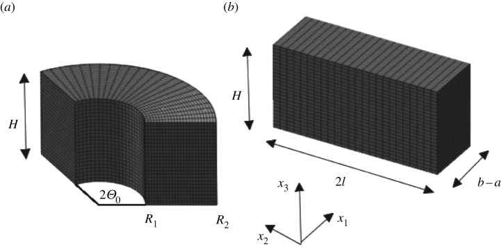
(a) A circular cylindrical sector with internal and external radii R1 and R2, respectively, and sector angle 2Θ0 straightened (b) under plane strain conditions into a rectangular block of thickness b−a and length 2l.
The corresponding deformation gradient F has the form
| 2.5 |
where ER,EΘ,EZ and e1,e2,e3 are the cylindrical polar and Cartesian unit basis vectors in the reference and deformed configurations, respectively. It follows that the Eulerian principal directions of the deformation (defined as the directions of the eigenvectors of the left Cauchy–Green deformation tensor B=FFT) are the Cartesian basis vectors and that the principal stretches are
| 2.6 |
We consider an incompressible isotropic hyperelastic material with strain energy W=W(λ1,λ2,λ3) per unit volume, so that the Cauchy stress tensor can be written as
| 2.7 |
where σ1,σ2,σ3 are the principal Cauchy stresses given by [8]
 |
2.8 |
p being a Lagrange multiplier associated with the incompressibility constraint λ1λ2λ3=1, which is automatically satisfied by (2.6).
Henceforth, it is convenient to use the notation λ2=λ, λ1=λ−1, and to introduce the function  of a single deformation variable defined by
| 2.9 |
from which, on use of (2.8), we obtain
| 2.10 |
As the deformation depends only on the single variable R (or x1), the second and third components of the equilibrium equation div σ=0 in the absence of body forces show that p is independent of x2 and x3, and the first component yields simply dσ1/dx1=0; hence σ1 is a constant. Then, by taking the boundary R=R1, for example, to be traction free it follows that σ1≡0, and hence
| 2.11 |
If required, the value of σ3 needed to maintain the plane strain condition may be obtained in terms of λ from (2.8)3 with p=λ1∂W/∂λ1.
Next, we compute the resultant normal force N and moment M (about the origin of the Cartesian coordinate system) on the end face x2=l of the block. They are given by
 |
2.12 |
Note that because σ2 is independent of x2, N and M are in fact the same on any section of the block normal to the x2-direction. By a change of variables, we arrive at
 |
2.13 |
where
 |
2.14 |
are the values of the stretch λ on the faces x1=a and x1=b, respectively, of the straightened block. Except for large values of |N|, it is expected that the circumferential elements on the ‘inner’ face of the straightened block are extended and those on the ‘outer’ face are contracted, i.e. λa>1 and λb<1, in which case, by (2.14) and the definition of A, it would follow that l belongs to the interval
| 2.15 |
We do not insist that this ordering holds in general, but it turns out that it gives a necessary and sufficient condition for the existence of a plane where λ=1 (with equation x1=l/2Θ0) in the straightened block, which we refer to as the neutral plane, or neutral axis in the (x1,x2) plane. This is the case when either M=0 or N=0, the two examples we analyse in §3, if we impose the physically reasonable requirement that the stress σ2 be positive (negative) when λ>1 (<1), i.e.
| 2.16 |
These inequalities certainly hold when the strain-energy function W satisfies the strong ellipticity condition. Indeed, by (2.10) we have
 |
2.17 |
because of the Baker–Ericksen inequalities, which are a consequence of the strong ellipticity condition [2]. Then, clearly, (2.16) readily follows.
As an example of the large straightening deformation, we consider the neo-Hookean material, for which
| 2.18 |
where μ>0 is the ground state shear modulus. For the plane strain problem this reduces to
| 2.19 |
We then calculate
 |
2.20 |
and
 |
2.21 |
Through this explicit example, which as far as we are aware is not available in the literature, it can be seen that in order to describe the straightening deformation, for any given Θ0, either the loads can be prescribed, i.e. N (or M) can be prescribed and then the corresponding A and M (or N) can be computed from equation (2.13) with (2.14), or the deformed geometry can be described, i.e. the length 2l can be prescribed, hence fixing A, and then N and M deduced from equation (2.13) with (2.14). In this paper, following considerations of Hill [3] in respect of a spherical cap, we deal with three case studies that are important physically:
(i) the sector is straightened by end couples alone (N=0);
(ii) the sector is straightened by vice-clamps (M=0); and
(iii) with NM≠0 in general, the final length 2l of the straightened sector is determined at the onset of instability.
For instance, if the deformation for the neo-Hookean material is achieved by the application of moments alone, as in Case (i), then N=0 and A is determined by
 |
2.22 |
in which case M depends on the geometry only through R1 and R2.
3. Examples of straightening
This section is concerned with deformations that are achieved by the application of two special systems of forces, that corresponding to zero resultant normal force, N=0, and that corresponding to zero resultant moment, M=0, i.e. Cases (i) and (ii) above, respectively. With reference to (2.12), we see that the difference between these two cases arises from the different distributions of the stress σ2 with respect to x1 in [a,b].
We focus on constitutive models that satisfy the strong ellipticity condition, which, for plane strain, consists of the inequalities [8]
 |
3.1 |
These two inequalities are satisfied by many standard strain-energy functions, including the neo-Hookean model:
| 3.2 |
where I1=tr B and μ is a constant; the Varga model [9]:
| 3.3 |
where i1=tr(B1/2); the Fung–Demiray model [10]:
| 3.4 |
where c is a constant and the Gent model [11]:
 |
3.5 |
where Jm is a constant and the range of deformation is limited by the condition that I1−3<Jm. In each case, μ (>0) is the shear modulus of the material in the undeformed configuration, given by  .
.
(a). Straightening by end couples
The system of loads consists of end couples alone when N=0, which is the case we consider here. If N=0 then σ2 must take both positive and negative signs in the interval [a,b], and, in particular, there must be a value of x2 where σ2=0, and hence, by (2.16) λ=1, so that
| 3.6 |
By virtue of (2.14)1, this leads to the restriction
 |
3.7 |
on λb, wherein we have defined, for later convenience, the notation ρ. In this case, by (2.13)1, we must investigate the existence of positive roots for λb in the interval (3.7) of the equation
 |
3.8 |
with λa=λb/ρ for fixed ρ.
To this end, we introduce the function f(λb) defined by
 |
3.9 |
By virtue of (2.16), we have
 |
3.10 |
and by differentiation
 |
3.11 |
By (2.16) and (3.6), this is clearly positive, and we conclude that f is strictly increasing, and so f has a unique zero, say  , in interval (3.7). Consequently, a circular cylindrical sector made of an incompressible isotropic elastic material can be straightened by applying terminal couples only. This result is universal to all constitutive models with strain-energy functions
  continuously differentiable in
  and satisfying inequalities (2.16). The corresponding moment is
 |
3.12 |
For illustration, we now report some analytical and numerical results for the solution of equation (3.8).
For the neo-Hookean material (3.2), we obtain
 |
3.13 |
For the Varga material, the explicit solution of (3.8) and the corresponding moment are given by
 |
3.14 |
For Fung–Demiray material (3.4), there are no explicit solutions, and a numerical resolution is required. Figure 2a,b displays the stretch  as a function of the ratio ρ=R1/R2 for the neo-Hookean, Varga and Fung–Demiray materials. In particular, in plotting figure 2b, we took the Fung–Demiray energy density with constants used in [12] to model ‘young’ human arteries (c=1.0) and ‘old’ arteries (c=5.5).
Figure 2.
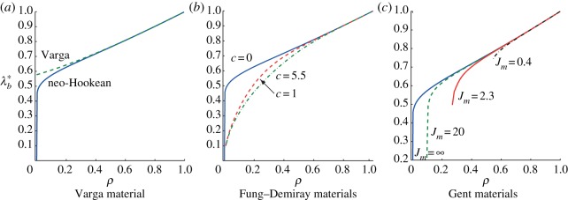
Circumferential stretch  as a function of the radii ratio ρ=R1/R2 for the straightening of blocks by end-couples only: (a) Varga and neo-Hookean materials; (b) Fung–Demiray materials with stiffening parameters c=5.5, c=1.0 and
  (neo-Hookean limit) and (c) Gent materials with stiffening parameters Jm=0.4, Jm=2.3, Jm=20.0 and
  (neo-Hookean limit). (Online version in colour.)
As already pointed out, the assumptions that the function  is continuously differentiable and satisfies inequalities (2.16) are fundamental for proving the existence and uniqueness of the straightened configuration. We now show that, by means of slight changes, this result can be extended to Gent materials (3.5). For these materials, the function
  reads
reads
 |
3.15 |
and it is continuously differentiable in the interval  , where
 |
3.16 |
is the upper bound on the stretch in (plane strain) uniaxial tension. Therefore, in order to straighten a circular cylindrical sector made of a Gent material, the circumferential stretch must belong to the interval  throughout the thickness of the block. As a consequence of this restriction, if
  then the condition
  implies that
  throughout the block. On the other hand, as
  satisfies the inequalities (2.16),
 |
3.17 |
is an increasing function such that
| 3.18 |
and, if  , fG(ρ)<0. We may then conclude that fG has a unique zero at
| 3.19 |
It is worth noting that, in the light of (3.19),  as
as  (figure 2c).
(b). Straightening by vice-clamps
Now we investigate the existence of positive roots for λb in the interval (3.7) when M=0, that is
 |
3.20 |
Following arguments similar to those used in §3a, we introduce the function g(λb) defined by
 |
3.21 |
By virtue of (2.16), we have
 |
3.22 |
and by differentiation
 |
3.23 |
which, in view of (2.16) and (3.6), is positive, implying that g is strictly increasing. Therefore, by virtue of (3.22), g has a unique zero, say  , in the interval (ρ,1). Consequently, a circular cylindrical sector made of an incompressible isotropic elastic material can be straightened by applying a system of forces with zero resultant moment. By following the same arguments as in the previous section, one can prove that this result is valid not only for all the constitutive models with strain-energy functions
  continuously differentiable in
  and satisfying the inequalities (2.16), but also for Gent materials. The corresponding resultant normal force is
 |
3.24 |
For the neo-Hookean and Varga models, the explicit solutions of (3.20), which are illustrated in figure 3a, and the corresponding total normal force are, respectively,
 |
3.25 |
and
 |
3.26 |
For the Fung–Demiray and Gent materials, one can solve equation (3.20) only numerically. Figure 3b,c shows  as a function of ρ for different values of the material parameters c and Jm.
Figure 3.
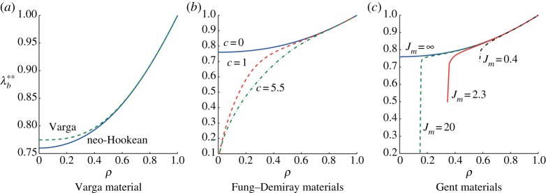
Circumferential stretch  as a function of the radii ratio ρ=R1/R2 for the straightening of blocks by vice-clamps: (a) Varga and neo-Hookean materials; (b) Fung–Demiray materials with stiffening parameters c=5.5, c=1.0 and
  (neo-Hookean limit) and (c) Gent materials with stiffening parameters Jm=0.4, Jm=2.3, Jm=20.0 and
  (neo-Hookean limit). Note that different vertical scales are used in the three plots so as to avoid losing information. Thus, although not immediately apparent, the continuous curves in (a–c) are the same and are for the neo-Hookean model. (online version in colour.)
We end this section by pointing out that, independently of the form of the strain-energy function, we have
| 3.27 |
We have already shown that  and
and  belong to the interval (ρ,1). Furthermore, from (2.16), (3.9) and (3.21) we deduce that
 |
3.28 |
Hence, as f and g are increasing in the interval (ρ,1), inequality (3.27) follows immediately.
(c). Thin sectors
For thin sectors, that is sectors with thickness much smaller than the radius of the (undeformed) inner face, some general conclusions can be established about the straightened configuration. For the asymptotic analysis, we introduce the small parameter ε>0 defined as
| 3.29 |
First we look at the straightening of a sector by the application of end couples, and we rewrite f in (3.9) as a function of ε, specifically
 |
3.30 |
Expanding F(ε) as a Maclaurin series in the parameter ε up to the fifth order, substituting into the equation f(λb)=0 and dropping a common factor ε, yields the equation
 |
3.31 |
Next, we expand λb in terms of ε to the fourth order
| 3.32 |
Substituting this into the previous expansion and equating to zero the coefficients of each power in the resulting expression, we obtain, at zero order
| 3.33 |
and hence, by (2.16), λ(0)=1. Using this result in the first-order term, we obtain
| 3.34 |
and because  , we deduce that
  . Then, the second-order term yields
| 3.35 |
The resulting expression for λb, to the second order in ε, is therefore
 |
3.36 |
However, for plane strain, there is the universal result  (e.g. [13]), so that the above formula reduces to
| 3.37 |
Proceeding in a similar way (without showing the lengthy details), we obtain
 |
3.38 |
Note, in particular, that the material properties do not enter until the fourth order, i.e. the results are independent of the form of strain-energy function up to order ε3.
Similarly, with an asymptotic analysis in the case of straightening by applying a resultant force only (M=0), we find that, for thin cylindrical sectors, the result analogous to (3.38) is
 |
3.39 |
The universal result used in (3.38) and (3.39) can be confirmed by, for example, expanding the strain-energy function in terms of the Green strain tensor E=(FTF−I)/2 in the form
| 3.40 |
where μ,  and
and  are the second-, third- and fourth-order elastic constants, respectively (see Destrade & Ogden [14] and references therein). For the plane strain specialization, we have
| 3.41 |
and by computing the successive derivatives of  we obtain
 |
3.42 |
Note that we established the last identity by expanding W to one order further than in (3.40) [15]. However, the next order terms do not contribute to the expression for  .
.
4. Incremental stability
We now study the stability of the deformed rectangular configuration by considering a superimposed incremental displacement u, with components (u1,u2,u3). We denote the displacement gradient gradu by L, which has components Lij=∂ui/∂xj. When linearized the incremental incompressibility condition reads
| 4.1 |
in the usual summation convention for indices, where a subscript i following a comma signifies differentiation with respect to xi.
The corresponding linearized incremental nominal stress referred to the deformed configuration, denoted  , is given by [8]
| 4.2 |
where a superposed dot signifies an increment, the zero subscript indicates evaluation in the deformed configuration, I is the identity tensor and  is the fourth-order tensor of instantaneous elastic moduli. In components, this reads
| 4.3 |
where δij is the Kronecker delta. Referred to the Eulerian principal axes of the underlying deformation, the only non-trivial components of  are given by [8]
| 4.4 |
and
 |
4.5 |
with Wi=∂W/∂λi, Wij=∂2W/∂λi∂λj, noting the major symmetry  . For λi=λj, the specializations of (4.5) can be obtained by taking the limit
  but are not needed here.
For the neo-Hookean material (2.18), these reduce to
| 4.6 |
In the absence of body forces, the incremental equilibrium equation has the general form
| 4.7 |
but here we consider plane incremental deformations with u3=0 and u1 and u2 independent of x3, in which case the linearized incremental incompressibility condition becomes
| 4.8 |
Furthermore, as p and the deformation, and hence the components of  , depend only on x1, the components of equation (4.7) reduce to
| 4.9 |
Therefore,  is independent of x3. From (4.2), the components of the incremental nominal stress
  appearing in (4.9) are
| 4.10 |
| 4.11 |
| 4.12 |
and
| 4.13 |
in the second of which we have used σ1=0.
We seek solutions of the form
| 4.14 |
where n=kπA/Θ0 is the mode number and the integer k is the number of wrinkles. Then, the components of incremental nominal stress (4.13) have a similar form, which we write as
| 4.15 |
with
| 4.16 |
| 4.17 |
| 4.18 |
and
| 4.19 |
and incremental incompressibility condition (4.8) yields
| 4.20 |
From (4.17), we obtain
| 4.21 |
where
| 4.22 |
On use of the above equations followed by elimination of S21 and S22 in favour of U1, U2, S11 and S12, incremental equilibrium equations (4.9) yield expressions for S′11 and S12′ in terms of U1, U2, S11 and S12.
Then, by introducing the four-component displacement–traction vector η=[U1,U2,iS11,iS12]T, we can cast the governing equations in the Stroh form
 |
4.23 |
where the real Stroh matrix G has the form
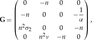 |
4.24 |
with
| 4.25 |
We consider the incremental traction to vanish on the inner and outer faces, i.e.
| 4.26 |
If a solution of the incremental equations can be found subject to these boundary conditions, then possible equilibrium states exist in a neighbourhood of the straightened configuration, signalling the onset of instability of that configuration. The value of 1/(AR2)=λb at this point is referred to as the critical value for the stretch and denoted by λcr. Then, from (2.4) it follows that
 |
4.27 |
which allows for the complete determination of the straightened geometry just prior to instability. In particular, the lengths of the block in the x1 and x2 directions are, respectively, given by
 |
4.28 |
Note that if  , where
  is the unique positive solution of (3.8), then the cylindrical sector can be straightened by applying a moment alone without encountering any instability phenomenon. Similarly for a cylindrical sector straightened by vice-clamps, if
  (this case is illustrated in figure 4 for a neo-Hookean material).
Figure 4.
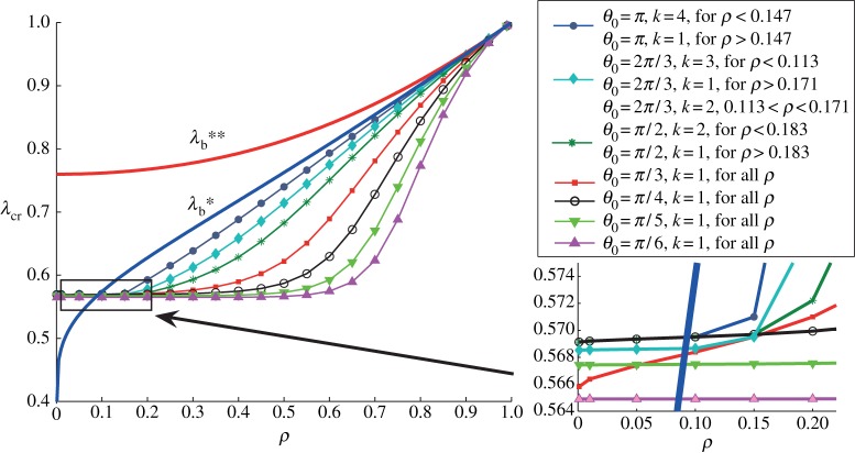
Critical value of the stretch λcr as a function of the radii ratio ρ=R1/R2 for the straightening of a neo-Hookean material, for different angles Θ0. (Online version in colour.)
5. Numerical results
In this section, we investigate the possibility of solving numerically the incremental instability problem. The Stroh form of the governing equations is numerically stiff and calls for the implementation of a robust algorithm. In the incremental stability literature, the compound matrix method has been used successfully to solve a variety of stiff problems, including eversion [16,17] and compression [18] of cylindrical tubes, bending [12,19,20] and combined bending and compression [21] of a straight block, bending of a sector [22], and pressurization of a spherical shell [23]. It turns out that for the problem considered here the compound matrix is itself singular, a feature that seems to be unique to the straightening stability problem. We manage to circumvent this problem by constructing a reduced, non-singular, compound matrix. We then use the impedance matrix method, which proves to be more precise numerically for this problem. It also provides for a complete field description of the incremental displacement solution.
(a). Compound matrix method
Let η(1)(x1), η(2)(x1) be two linearly independent solutions of (4.23), and from them generate the six compound functions  , defined by
 |
5.1 |
and
 |
5.2 |
Now, computing the derivatives of ϕi with respect to x1 yields the so-called compound equations
 |
5.3 |
where  and A, the compound matrix, has the form
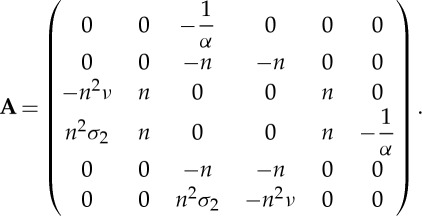 |
5.4 |
Compound equations (5.3) must be integrated numerically, starting with the initial condition
| 5.5 |
and aiming at the target condition
| 5.6 |
according to (4.26).
However, we observe that  , the first case in solid mechanics to our knowledge where a compound matrix is singular. Because of this situation, the numerical integration of Cauchy problem (5.3)–(5.5) will obviously encounter severe difficulties. In any event, the difficulty can be by-passed by noting that from (5.3) to (5.5) it follows that
 |
5.7 |
It then follows that we can construct a reduced compound matrix
 by introducing five reduced compound functions
  , defined by
| 5.8 |
so that from (5.3) and (5.7)2, the governing equations can be written as
 |
5.9 |
where  and
and  has the form
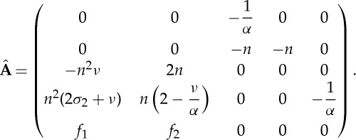 |
5.10 |
Here,
 |
5.11 |
It is easy to check that  . Hence, we may now integrate numerically the non-singular initial value problem (5.9) and (5.10) instead of the original compound equations with singular Jacobian. Finally, in view of (5.5) and (5.8), the initial condition for this system is
| 5.12 |
and in view of (5.6) and (5.8)2, the target condition is
| 5.13 |
To implement the (reduced) compound matrix method, we first non-dimensionalized equations (5.9)–(5.12) and specialized them to the neo-Hookean model. Then we applied an initial value solver (ode45 or ode15s routines in Matlab), together with the dichotomy method in order to satisfy target condition (5.13).
This approach is a shooting-like technique for which convergence and stability can depend on the well- or ill-conditioning of the underlying boundary value problem and of the target root finder problem. The numerical drawbacks and challenges of the shooting techniques are highlighted in many textbooks (e.g. [24]).
In our case, for a set of fixed values of ρ=R1/R2∈(0,1), the bisection technique yields a sequence of values λj to approximate λcr and stops the iterations when: (a) the residual |F(λj)|=|ψ5(b;λj)|≤tolr and (b) the error estimate |λj−λj−1|≤tole. Both criteria must be used to check the goodness of the approximation. If the usual assumptions of the bisection method are satisfied on the starting localization interval I0=[λ0,λ1] (that is F(λ0)F(λ1)<0) then the method will converge, i.e. by definition the criterion (b) will be always be satisfied. We set tole=10−12 and tolr=10−4, and included a control on the maximum number of iterations allowed (itmax=40). We applied the same shooting approach when using the compound matrix method and the impedance matrix method (next section). Both methods yielded the same results, although the former gave quite high residuals when k>2 and ρ is small. However, the values of λcr identified by the two methods were the same up to at least four significant digits even in the worst case of high residuals. For all intents and purposes, both the compound matrix and the impedance matrix methods provide the desired level of precision for the critical stretch of compression. The latter has the advantage of also providing a complete description of the incremental fields, as we now see.
(b). Impedance matrix method
Here, we follow Shuvalov [25] and introduce the matricant solution M(x1,a) of (4.23) and (4.24) defined as the matrix such that
| 5.14 |
which has the following 2×2 block structure
 |
5.15 |
I(4) being the fourth-order identity matrix.
We now use the incremental boundary condition S(a)=0 in (5.14) and (5.15) to establish that
| 5.16 |
is the conditional impedance matrix. Substituting this impedance matrix into the incremental equilibrium equations (4.23) and (4.24) gives
 |
5.17 |
where
 |
5.18 |
are the 2×2 sub-blocks of G. Eliminating U between the two equations in (5.17) results in the following Riccati matrix differential equation for Za:
 |
5.19 |
It is well behaved and can be integrated numerically in a robust way, subject to the initial condition,
| 5.20 |
which follows from (5.16)2 and (5.14)2. The target condition is
| 5.21 |
which is met by adjustment of the critical value λcr for the stretch λb, by using a bisection approach as described in §4a, with the same tolerance values for the stopping criteria. Then, S(b)=Za(b)U(b)=0 means that
 |
5.22 |
and this ratio determines the form of the wrinkles on the outer face of the straightened block.
To proceed, we introduce the dimensionless quantities
 |
5.23 |
where  is again the shear modulus in the reference configuration. Substitution of (5.23) into equations (4.23) and (4.24) yields
 |
5.24 |
with  and
and
 |
5.25 |
The dimensionless version of the Riccati equation (5.19) is then
 |
5.26 |
where
 |
5.27 |
and
 |
5.28 |
The target condition to append to (5.26) for finding the critical stretch λcr is  . Finally, in order to determine the entire displacement field U throughout the straightened block once equation (5.26) is solved and the critical value λcr has been found, we integrate the equation
 |
5.29 |
numerically (again using the ode45 Matlab solver) from the initial conditions
 |
5.30 |
at y=1 to the face at y=ρ2.
(c). Neo-Hookean materials
For a neo-Hookean material with strain-energy function (2.18), we obtain the non-dimensional quantities
 |
5.31 |
which depend only on y and λcr.
In figure 4, we provide plots of the critical value λcr versus ρ=R1/R2 corresponding to loss of stability of some straightened sectors of neo-Hookean materials. We take in turn Θ0=π,2π/3,π/2,π/3,π/4,π/5,π/6. The number of wrinkles k appearing on the compressed side of the block depends on the angle Θ0 and on ρ. Hence, for Θ0=π there are four wrinkles when ρ<0.1469 and only one when ρ>0.1469. For Θ0=2π/3, there are three wrinkles when ρ<0.1131, two wrinkles when 0.1131<ρ<0.1717 and one wrinkle when ρ>0.1717. For Θ0=π/2, there are two wrinkles when ρ<0.1833 and one wrinkle when ρ>0.1833. For all the other values of the opening angle, there is only one wrinkle for any value of ρ in (0,1). These results are summarized in the legend on the right of figure 4.
In the thick sector–small wavelength limit (i.e. as  and
and  ), we recover the critical threshold for surface instability in plane strain of Biot [26] (i.e.
  ).
).
We also plot the curves for  and
and  , giving the circumferential stretch of a cylindrical sector straightened by end couples and by vice-clamps, respectively. We see that a sector straightened by applying a system of forces and no moment (vice-clamps) never buckles on its outer face because
  is always greater than λcr. However, a sector straightened by moments alone and no normal forces (end couples) can buckle when ρ is smaller than 0.09 (see the zoom in figure 4). When ρ is greater than 0.09, a cylindrical sector straightened by end-couples does not present wrinkles on its outer face.
(d). Gent materials
To investigate the influence of material parameters on the behaviour of straightened blocks, we use the Gent model (3.5). For its non-dimensional quantities in the Riccati equation (5.26), we find
 |
5.32 |
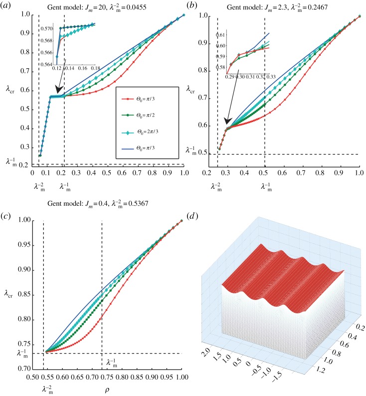
highlighting the role played by the stiffening parameter Jm; see the illustrations in figure 5.
Table 1.
Description of the results displayed in figure 5 for the bifurcation curves of straightened Gent materials. There are three different types of Gent materials (Jm=20, rubber; Jm=2.3, young artery; Jm=0.4, old artery) and four different angles (Θ0=π/3,π/2,2π/3,π). Each curve is made of several pieces, each corresponding to the earliest bifurcation mode for a given value of ρ of the sector, with corresponding number of wrinkles k in the third column.
| Jm | angle | number of wrinkles |
|---|---|---|
| 20 | Θ0=π/3 | k=1 for 0.045<ρ≤1 |
| 20 | Θ0=π/2 | k=1 for 0.045<ρ<0.11 and 0.21<ρ≤1 |
| k=2 for 0.11<ρ<0.21 | ||
| 20 | Θ0=2π/3 | k=1 for 0.045<ρ<0.11 and 0.21<ρ≤1 |
| k=2 for 0.11<ρ<0.12 and 0.13<ρ<0.21 | ||
| k=3 for 0.12<ρ<0.13 | ||
| 20 | Θ0=π | k=1 for 0.045<ρ<0.10 and 0.19<ρ≤1 |
| k=2 for 0.10<ρ<0.11 | ||
| k=3 for 0.11<ρ<0.12 and 0.17<ρ<0.19 | ||
| k=4 for 0.12<ρ<0.17 | ||
| 2.3 | Θ0=π/3 | k=1 for 0.25<ρ≤1 |
| 2.3 | Θ0=π/2 | k=1 for 0.25<ρ<0.28 and 0.30<ρ≤1 |
| 2.3 | Θ0=2π/3 | k=1 for 0.25<ρ<0.28 and 0.31<ρ≤1 |
| k=2 for 0.28<ρ<0.31 | ||
| 2.3 | Θ0=π | k=1 for 0.25<ρ<0.27 and 0.31<ρ≤1 |
| k=2 for 0.27<ρ<0.28 | ||
| k=3 for 0.28<ρ<0.31 | ||
| 0.4 | Θ0=π/3 | k=1 for 0.54<ρ≤1 |
| 0.4 | Θ0=π/2 | k=1 for 0.54<ρ≤1 |
| 0.4 | Θ0=2π/3 | k=1 for 0.54<ρ≤1 |
| 0.4 | Θ0=π | k=1 for 0.54<ρ≤1 |
Figure 5.
Instability of a straightened homogeneous circular cylindrical sector modelled by the Gent strain-energy function. (a–c) The critical stretch λcr for wrinkling versus the radii ratio ρ=R1/R2 for different open angles Θ0, in the cases where the Gent stiffening parameter is (a) Jm=20 (rubber), (b) Jm=2.3 (old aorta) and (c) Jm=0.4 (young aorta). As summarized in table 1, the number of wrinkles k depends on the constitutive parameter Jm, on the angle Θ0 and ρ. For instance, for Jm=20, Θ0=π and ρ=0.15, the number of wrinkles is k=4; see (a) and (d). (Online version in colour.)
As a circular cylindrical sector made of a Gent material can be straightened provided that  and the circumferential stretch on the outer face λb belongs to the interval
  , as indicated in §3a, λcr tends to
  as
as  . Consequently, when Jm is large enough but finite, the marginal stability curves for Gent and neo-Hookean materials are qualitatively similar in the interval
  , whereas they differ in the range
  ; compare, for instance, figure 5a with figure 4. As
  , the behaviour of neo-Hookean material is recovered.
Finally, we integrated (5.29) for a case in which four wrinkles appear on the straightened face to generate the entire incremental displacement field (up to an arbitrary multiplicative factor), as illustrated in figure 5d.
Funding statement
Partial funding from the Royal Society of London (International Joint Project grant for M.D., R.W.O. and L.V.), from the Istituto Nazionale di Alta Matematica (Marie Curie COFUND Fellowship for L.V.; GNCS Visiting Professor Scheme for M.D. and I.S.) and from the Ministero dell'Istruzione, dell'Università della Ricerca (PRIN-2009 project Matematica e meccanica dei sistemi biologici e dei tessuti molli for I.S.) is gratefully acknowledged.
References
- 1.Ericksen JL. 1954. Deformations possible in every isotropic, incompressible, perfectly elastic body. Zeits. Angew. Math. Phys. 5, 466–489 (doi:10.1007/BF01601214) [Google Scholar]
- 2.Truesdell C, Noll W. 2004. The non-linear field theories of mechanics. Berlin, Germany: Springer [Google Scholar]
- 3.Hill JM. 1973. Partial solutions of finite elasticity—three dimensional deformations. Zeits. Angew. Math. Phys. 24, 609–618 (doi:10.1007/BF01588162) [Google Scholar]
- 4.Aron M, Christopher C, Wang Y. 1998. On the straightening of compressible, nonlinearly elastic, annular cylindrical sectors. Math. Mech. Solids 3, 131–145 (doi:10.1177/108128659800300201) [Google Scholar]
- 5.Aron M. 2000. Some remarks concerning a boundary-value problem in nonlinear elastostatics. J. Elasticity 60, 165–172 (doi:10.1023/A:1011083214837) [Google Scholar]
- 6.Aron M. 2005. Combined axial shearing, extension, and straightening of elastic annular cylindrical sectors. IMA J. Appl. Math. 70, 53–63 (doi:10.1093/imamat/hxh059) [Google Scholar]
- 7.Destrade M, Ogden RW, Sgura I, Vergori L. In press. Straightening wrinkles. J. Mech. Phys. Solids. (doi:10.1016/j.jmps.2014.01.001) [DOI] [PMC free article] [PubMed] [Google Scholar]
- 8.Ogden RW. 1997. Non-linear elastic deformations. New York, NY: Dover [Google Scholar]
- 9.Varga OH. 1966. Stress–strain behavior of elastic materials. New York, NY: Interscience [Google Scholar]
- 10.Demiray H. 1972. A note on the elasticity of soft biological tissues. J. Biomech. 5, 309–311 (doi:10.1016/0021-9290(72)90047-4) [DOI] [PubMed] [Google Scholar]
- 11.Gent AN. 1996. A new constitutive relation for rubber. Rubber Chem. Technol. 69, 59–61 (doi:10.5254/1.3538357) [Google Scholar]
- 12.Destrade M, Ni Annaidh A, Coman CD. 2009. Bending instabilities of soft biological tissues. Int. J. Solids Struct. 46, 4322–4330 (doi:10.1016/j.ijsolstr.2009.08.017) [Google Scholar]
- 13.Ogden RW. 1985. Local and global bifurcation phenomena in plane strain finite elasticity. Int. J. Solids Struct. 21, 121–132 (doi:10.1016/0020-7683(85)90029-0) [Google Scholar]
- 14.Destrade M, Ogden RW. 2010. On the third- and fourth-order constants of incompressible isotropic elasticity. J. Acoust. Soc. Am. 128, 3334–3343 (doi:10.1121/1.3505102) [DOI] [PubMed] [Google Scholar]
- 15.Ogden RW. 1974. On isotropic tensors and elastic moduli. Proc. Camb. Phil. Soc. 75, 427–436 (doi:10.1017/S0305004100048635) [Google Scholar]
- 16.Haughton DM, Orr A. 1997. On the eversion of compressible elastic cylinders. Int. J. Solids Struct. 34, 1893–1914 (doi:10.1016/S0020-7683(96)00122-9) [Google Scholar]
- 17.Fu YB, Lin YP. 2002. A WKB analysis of the buckling of an everted neo-Hookean cylindrical tube. Math. Mech. Solids 7, 483–501 (doi:10.1177/108128650200700502) [Google Scholar]
- 18.Dorfmann A, Haughton DM. 2006. Stability and bifurcation of compressed elastic cylindrical tubes. Int. J. Eng. Sci. 44, 1353–1365 (doi:10.1016/j.ijengsci.2006.06.014) [Google Scholar]
- 19.Coman C, Destrade M. 2008. Asymptotic results for bifurcations in pure bending of rubber blocks. Q. J. Mech. Appl. Math. 61, 395–414 (doi:10.1093/qjmam/hbn009) [Google Scholar]
- 20.Roccabianca S, Bigoni D, Gei M. 2011. Long-wavelength bifurcations and multiple neutral axes in elastic multilayers subject to finite bending. J. Mech. Mater. Struct. 6, 511–527 (doi:10.2140/jomms.2011.6.511) [Google Scholar]
- 21.Haughton DM. 1999. Flexure and compression of incompressible elastic plates. Int. J. Eng. Sci. 37, 1693–1708 (doi:10.1016/S0020-7225(98)00141-4) [Google Scholar]
- 22.Destrade M, Murphy JG, Ogden RW. 2010. On deforming a sector of a circular cylindrical tube into an intact tube: existence, uniqueness, and stability. Int. J. Eng. Sci. 48, 1212–1224 (doi:10.1016/j.ijengsci.2010.09.011) [Google Scholar]
- 23.Fu YB. 1998. Some asymptotic results concerning the buckling of a spherical shell of arbitrary thickness. Int. J. Non-Linear Mech. 33, 1111–1122 (doi:10.1016/S0020-7462(97)00075-9) [Google Scholar]
- 24.Ascher UM, Mattheij RM, Russell RD. 1995. Numerical solution of boundary value problems for ordinary differential equations. Philadelphia, PA: SIAM Publications [Google Scholar]
- 25.Shuvalov AL. 2003. A sextic formalism for three-dimensional elastodynamics of cylindrically anisotropic radially inhomogeneous materials. Proc. R. Soc. Lond. A 459, 1611–1639 (doi:10.1098/rspa.2002.1075) [Google Scholar]
- 26.Biot M. 1963. Surface instability of rubber in compression. Appl. Sci. Res. A12, 168–182 [Google Scholar]


