Abstract
We have prepared and thoroughly characterized, using X-ray crystallographic, spectroscopic, and computational methods, the diazide adduct of [FeIII(dapsox)(H2O)2]1+ [dapsox=2,6-diacetylpyridinebis(semioxamazide)] (1), alow-molecular weight, functional analogue of iron superoxide dismutase (FeSOD). The X-ray crystal structure of the dimeric form of 1, (Na[FeIII(dapsox)(N3)2] DMF)2 (2) shows two axially coordinated, symmetry inequivalent azides with differing Fe–N3 bond lengths and Fe–N–N2 bond angles. This inequivalence of the azide ligands likely reflects the presence of an inter-dimer H-bonding interaction between a dapsox NH group and the coordinated nitrogen of one of the two azide ligands. Resonance Raman (rR) data obtained for frozen aqueous solution and solid-state samples of 2 indicate that the azides remain inequivalent in solution, suggesting that one of the azide ligands of 1 engages in an intermolecular hydrogen bonding interaction with a water molecule. Density functional theory (DFT) and time-dependent DFT calculations have been used to study two different computational models of 1, one using coordinates taken from the X-ray crystal structure of 2, and the other generated via DFT geometry optimization. An evaluation of these models on the basis of electronic absorption, magnetic circular dichroism, and rR data indicates that the crystal structure based model provides a more accurate electronic structure description of 1, providing further support for the proposed intermolecular hydrogen bonding of 1 in the solid state and in solution. An analysis of the experimentally validated DFT results for this model reveals that the azides have both σ- and π-bonding interactions with the FeIII center and that more negative charge is located on the Fe-bound, rather than on the terminal, nitrogen atom of each azide. These observations are reminiscent of the results previously reported for the azide adduct of FeSOD and provide clues regarding the origin the high catalytic activity of Fe-dapsox for superoxide disproportionation.
Introduction
As a result of its ability to generate a wide variety of reactive oxygen and nitrogen species (ROS and RNS), the accumulation of the superoxide radical anion poses a significant threat to aero-tolerant organisms due to the devastating reactions of ROS and RNS with a wide variety of biological macromolecules, including DNA, proteins, and the cellular lipid bilayers.1,2 To help prevent the formation of ROS and RNS, these organisms produce enzymes called superoxide dismutases (SODs) that catalyze the disproportionation of two equivalents of superoxide and two protons to O2 and H2O2.1,3,4 While several distinct classes of SODs are known, each differs with respect to their metal cofactor(s) (i.e., Cu/Zn-, Fe-, Mn-, and NiSODs). However, all SODs use ping-pong type mechanisms for disproportionation, in which the metal center cycles between two oxidation states (see eqs. 1a and 1b).1,3–7
| (1a) |
| (1b) |
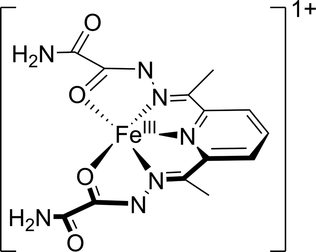
Though distinct from the Cu/Zn- and NiSODs, Fe- and Mn-containing SODs are structurally homologous, possessing virtually identical protein folds and active site structures.6,8–11 In each enzyme, the metal ion resides in a trigonal bipyramidal ligand environment with one aspartate and two histidines in the equatorial plane, and a third histidine residue and a solvent molecule, which is OH− in the oxidized (MIII) state and H2O in the reduced (MII) state, in the axial positions.12 Elevated cellular levels of superoxide have been implicated in a variety of diseases, including several inflammatory disorders, familial amyotrophic lateral sclerosis, Parkinson’s disease, and Alzheimer’s disease.13–16 Consequently, there is a significant interest in the discovery and optimization of synthetic, low molecular weight, functional analogues of SOD enzymes. One of the more promising enzyme mimics has been developed by Ivanović-Burmazović and co-workers, based on the so-called dapsox ligand [dapsox=2,6-diacetylpyridinebis(semioxamazide)].17,18 Dap-sox is a rigid acyclic dianion that will ligate to a metal in a roughly planar, pentachelate fashion; with the additional ligation of two axial molecules this yields a heptacoordinate, pseudo-pentagonal bipyramidal metal complex.18 Previous studies have shown that Fe(dapsox) catalyzes disproportionation at a rate approaching that of FeSOD to within about an order of magnitude.18 On the basis of our combined spectroscopic and computational studies of [FeIII(dapsox) (H2O)2]1+ (see Figure 1) and [FeII(H2dapsox)(H2O)2]2+, we have recently proposed a two-pronged mechanism in which a combination of a proton uptake coupled to FeIII ion reduction and π-backbonding in the FeII state are employed by the dapsox ligand to properly tune the FeIII/II redox potential for catalytic activity.19
Figure 1.
Chemical structure of [FeIII(dapsox)(H2O)2]1+.
To probe further the molecular mechanism employed by Fe(dapsox) for superoxide dismutation, it would be desirable to trap and characterize the actual catalytic intermediates. Unfortunately, the high turnover rate (kcat ∼ 107M−1 s−1)18 prevents the trapping of such species. However, it possible to employ the same approach used in the study of the SOD enzymes, which is to probe the enzyme’s interactions with an appropriate substrate analogue. In the case of SOD, the azide ion is a commonly used analogue, as it possesses the same charge and similar frontier orbitals as 6,9,20–28
Hence, to gain additional insight into the mechanism of catalytic superoxide disproportionation by Fe(dapsox), we have prepared the azide adduct of [FeIII(dapsox)(H2O)2]1+, and examined the geometric structure of its solid-state dimer, (Na[FeIII(dapsox)(N3)2] DMF)2 (2) using X-ray crystallography. The electronic structure of the anionic complex, [FeIII(dapsox)(N3)2]1− (1), was probed with electronic absorption (Abs), magnetic circular dichroism (MCD), and resonance Raman (rR) spectroscopies. Additionally, we carried out density functional theory (DFT) and time-dependent DFT (TD-DFT) calculations to generate an experimentally validated bonding description for 1. The results obtained in these studies provide detailed insight into the substrate analogue/FeIII(dapsox) interactions and reveal some interesting similarities between 1 and the azide adduct of FeIIISOD (N3-FeIIISOD).27,29
Experimental
Synthesis and Materials
Oxamic hydrazide was obtained from TCI America (Portland, OR) , while all other reagents including 1 – 15N isotopically labeled sodium azide (98%) were obtained from Sigma-Aldrich (St. Louis, MO). All reagents were used as received unless otherwise noted. Electrospray ionization mass spectrometry (ESI-MS) data were obtained using a Waters (Micromass) LCT spectrometer equipped a time-of-flight analyzer. IR spectra were taken on a Bruker TENSOR 27 using ATR techniques.
[FeIII(dapsox)(H2O)2]NO3
[FeIII(dapsox)(H2O)2]NO3 was synthesized as previously reported 19 with the exception that the product was not purified by recrystallization prior to the reaction with NaN3.
[FeIII (dapsox)(N3)2]1− (1)
550 mg (1.13 mmol) of [FeIII(dapsox)(H2O)2]NO3 was dissolved in 10 mL DMF and 735 mg (11.3 mmol) NaN3 was added to yield a dark red solution. The solution was then filtered and the product isolated by addition of Et2O until a dark red microcrystalline material was formed. Yield: 421 mg (79%). ESI-MS: m/z = 441 [M −(N3)2 +MeO +Na]+. IR (ATR, cm−1): 3443 (w), 3330 (w), 2051 [vs (N3)], 1698 (vs), 1615 (m), 1589 (w), 1564 (s), 1551 (s), 1518 (m), 1371 (w), 1296 (s), 1206 [w (N3)], 1150 (w), 1023 (w), 813 (w). Red block crystals suitable for crystallographic analysis were obtained by four rounds of crystallization by vapor diffusion of Et2O into a concentrated DMF solution of 1.
X-ray Crystallography
X-ray Crystal Structure Data
X-ray crystallographic data for (Na[FeIII(dapsox)(N3)2] · DMF)2 (2) were collected at 100 K using a Bruker SMART APEXII diffractometer with Cu Kα (λ = 1.54178 Å) radiation. The full sphere data collection routine was employed to survey the reciprocal space to the extent of a full sphere to a resolution of 0.82 Å. A total of 21682 data points were harvested by collecting 22 sets of frames with 0.7° scans in ω with an exposure time of 3,5, or 10 sec per frame. These highly redundant data sets were corrected for Lorentz and polarization effects. The absorption correction was based on fitting a function to the empirical transmission surface as sampled by multiple equivalent measurements.30 A successful solution by direct methods provided most non-hydrogen atoms from the E-map. The remaining non-hydrogen atoms were located in an alternating series of least-squares cycles and difference Fourier maps. Standard uncertainties of the bond distances and angles were computed from the variance-covariance matrix obtained for the structure refined to convergence with the least-squares method. All non-hydrogen atoms were refined with anisotropic displacement coefficients. All hydrogen atoms were included in the structure factor calculation at idealized positions and were allowed to ride on the neighboring atoms with relative isotropic displacement coefficients. Relevant crystallographic data are summarized in Table 1 and selected bond distances and angles are listed in Table 2. Complete crystallographic information is provided as Supporting Information in CIF format.
Table 1.
X-Ray Crystallographic Data for (Na[FeIII(dapsox)(N3)2]·DMF)2 (2)
| (Na[FeIII(dapsox)(N3)2]·DMF)2 | |
|---|---|
| Empirical formula | C32H42Fe2N28Na2O10 |
| Formula weight | 1134.6 |
| Temperature | 100(1) K |
| Wavelength | 1.54178 Å |
| Crystal system | Triclinic |
| Space group | P1̄ |
| Unit cell dimensions | a = 9.6720(9) Å α = 101.746(8)° |
| b = 10.2084(9) Å β = 90.285(6)° | |
| c = 11.7514(10) Å γ = 91.305(6)° | |
| Volume | 1135.64(17) Å3 |
| Z | 1 |
| dcalcd | 1.659 Mg/m3 |
| abs. coeff | 6.082 mm−1 |
| F(000) | 582 |
| Theta range | 3.84 to 72.26° |
| Reflections collected | 21682 |
| Independent reflections | 4252 [R(int) = 0.0250] |
| Resolution | 0.83 Å |
| Goodness-of-fit (F2) | 1.011 |
| Final R indices [I>2σ(I)] | R1 = 0.0251, wR2 = 0.0679 |
| R indices (all data) | R1 = 0.0256, wR2 = 0.0683 |
| diff. peak and hole | 0.551 and −0.373 e− Å−3 |
Table 2.
Selected Bond Lengths (Å) and Angles (deg) from the X-ray Crystal Structure of 2
| Bond Lengths | |||
|---|---|---|---|
| Fe–O1 | 2.1092(10) | Fe–O3 | 2.0521(10) |
| Fe–N3 | 2.1648(12) | Fe–N11 | 2.0531(13) |
| Fe–N4 | 2.1776(12) | Fe–N8 | 2.0990(13) |
| Fe–N5 | 2.1828(12) | ||
| Bond Angles | |||
| O1–Fe–N3 | 71.82(4) | N8–Fe–O1 | 91.92(5) |
| N3–Fe–N4 | 70.76(5) | N8–Fe–N3 | 86.66(5) |
| N4–Fe–N5 | 71.13(5) | N8–Fe–N4 | 88.87(5) |
| N5–Fe–O3 | 71.93(4) | N8–Fe–N5 | 90.07(5) |
| O3–Fe–O1 | 74.55(4) | N8–Fe–O3 | 88.98(5) |
| N11–Fe–O1 | 90.59(5) | N11–Fe–N8 | 175.84(5) |
| N11–Fe–N3 | 90.97(5) | Fe–N11–N12 | 121.08(11) |
| N11–Fe–N4 | 87.11(5) | Fe–N8–N9 | 119.02(10) |
| N11–Fe–N5 | 89.68(5) | N11–N12–N13 | 178.10(17) |
| N11–Fe–O3 | 94.89(5) | N8–N9–N10 | 179.68(17) |
Spectroscopy
Electronic Absorption (Abs) and Magnetic Circular Dichroism (MCD) Data
Room temperature Abs spectra were collected using a Varian Cary 5e spectrophotometer while low temperature Abs and MCD spectra were obtained with a JASCO J-715 spectropolarimeter in conjunction with an Oxford Instruments SM-4000 8 T superconducting magnetocryostat. Circular dichroism and glass-strain contributions to the MCD spectra were removed by subtracting the −7 T data from the +7 T data. All data were collected from either solution samples dissolved in 20:80 (v/v) 100 mM phosphate buffer, pH 2:glycerol or from solid-state mulls prepared by grinding solid 2 and adding polydimethylsiloxane.
Resonance Raman (rR) Data
Samples for rR spectroscopy were prepared as either an ∼18 mM solution of 1 in 100 mM phosphate buffer, pH 2 or as a powdered solid by grinding a sample of 2 with an excess of KBr, and were immediately frozen in liquid N2. rR data were obtained at 77 K upon excitation with an Ar+ ion laser (Coherent I-90) with ∼40–60 mW of laser power at the sample, using a ∼135° backscattering arrangement. The scattered light was dispersed with an Acton Research triple monochromator (equipped with 300, 1200, and 2400 grooves/mm gratings) and analyzed with a Princeton Instruments Spec X: 100BR deep-depletion, back-thinned CCD detector.
Computations
Geometry Optimizations
The ORCA 2.9.1 software package developed by Dr. Frank Neese31 was used to perform spin-unrestricted density functional theory (DFT) single-point calculations and geometry optimizations for 1 starting from coordinates taken from the X-ray crystal structure of 2. On the basis of the spectroscopic data obtained in this work, 1 was described as a high-spin (S=5/2), FeIII complex. The calculations were performed with Becke’s three-parameter hybrid functional for exchange32,33 and the Lee-Yang-Parr functional for correlation (B3LYP)34 and an integration grid of size 4 (302 Lebedev points). The polarized split-valence SV(P) basis set35 and the SV/C auxiliary basis set36 were used for all atoms except for the Fe ion and the ligating nitrogen and oxygen atoms, for which Ahlrich’s polarized-triple-ζ-valence (TZVP) basis set37 with one polarization function was employed. The geometry-optimized coordinates for the two computational models of 1 described in the text are provided in Tables S1 and S3.
Time Dependent DFT (TD-DFT)
TD-DFT calculations within the Tamm-Dancoff approximation38,39 were also performed with the ORCA 2.9.1 software package31 on both the geometry-optimized and the X-ray crystal structure based models of 1 using the same basis sets and functionals as for the single-point and geometry-optimization calculations. A total of 50 excited states were constructed from all MOs within ±3 hartree of the highest occupied molecular orbital (HOMO)/lowest unoccupied molecular orbital (LUMO) energy gap. The TD-DFT results were used to simulate Abs spectra assuming that each electronic transition gives rise to a Gaussian band with a full width at half-maximum of 3330 cm−1, a value that was chosen on the basis of our spectral analysis of the experimental data. Isosurface plots of the molecular orbitals (MOs) and electron density difference maps (EDDMs) were generated using the PyMol program with isodensity values of 0.05 au and 0.003 au, respectively40
Frequency Calculations
Vibrational frequencies as well as the IR and normal Raman intensities were calculated with the Gaussian ‘09 software package41 using same geometries, basis sets, and functionals as for the TD-DFT calculation. These results were used to construct Raman spectra by assuming that each vibrational transition gives rise to a Gaussian band with a full width at half-maximum of 13 cm−1.
Results
Experimental Studies
Crystal Structure
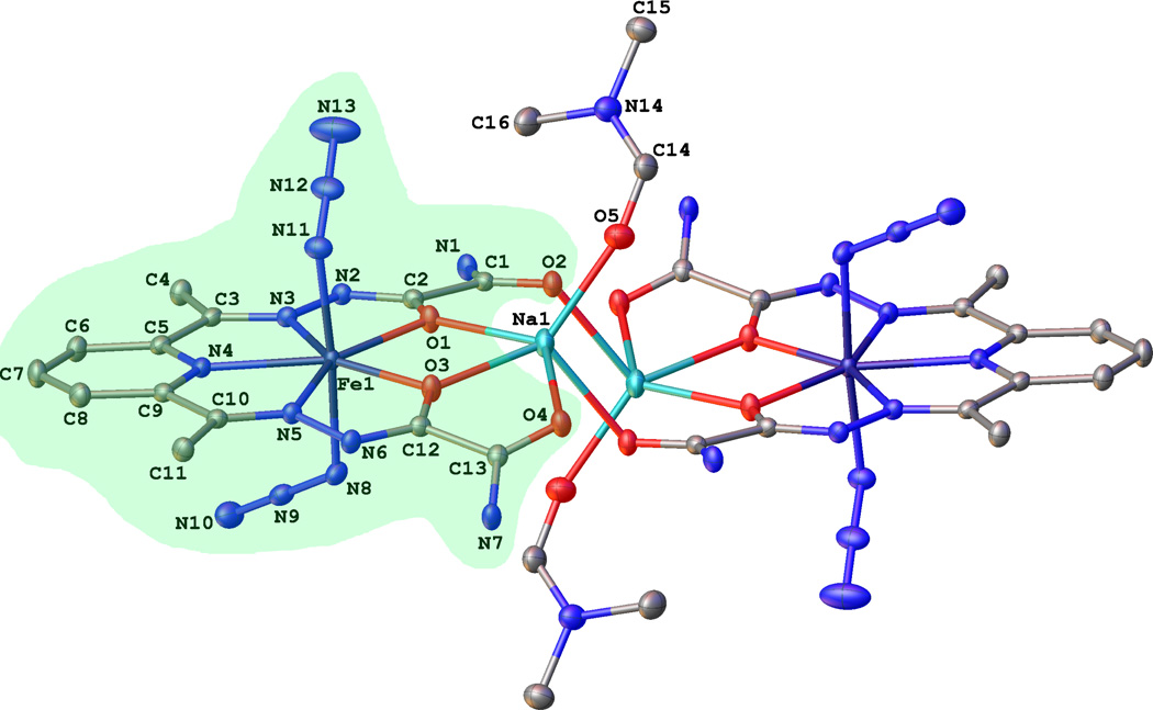
The 0.83 Å resolution X-ray crystal structure of (Na[FeIII(dapsox) (N3)2] · DMF)2 (2) reveals a dimer of pentagonal bipyramidal complexes, where in each the dapsox ligand coordinates equatorially in a pentachelate fashion and two azide ions coordinate axially (Figure 2). The unit cell also contains a Na+ counter-ion located between the two “arms” of the dapsox lig-and, where it forms favorable polar contacts with the four carbonyl oxygens, and a DMF solvent molecule disordered over two positions, with the major component present 81.4(3)% of the time. The two [FeIII(dapsox) (N3)2]1− (1) units have identical geometries as a result of the dimer occupying a crystallographic inversion center. The dapsox ligand adopts a fairly planar configuration around the FeIII center with the five ligating atoms having a mean deviation from planarity of 0.054 Å and the central FeIII ion being 0.0251(6) Å displaced from this plane. Additionally, the sum of the four chelate angles and the O1–Fe1–O3 angle (Table 2) for the dapsox ligand is 360.19°, close to the ideal value of 360° for a planar structure.
Figure 2.
Thermal ellipsoid representation (50% probability boundaries) of the X-ray crystal structure of 2. All hydrogen atoms and the minor components of the disordered DMF molecule are omitted for clarity. One of the two equivalent [FeIII(dapsox)(N3)2]1− (1) units is highlighted in green.
The two azides complete the pseudo-pentagonal bipyramidal geometry around the central iron ion with a close to linear N8 – Fe1 – N11 bond angle of 175.84(5)° and a N9-N8-N11-N12 torsion angle of 73.529(6)°. They are symmetry inequivalent and bind to the iron center in a bent manner with Fe–N–N2 bond angles of 119.02(10)° and 121.08(11)°. Further highlighting the inequivalence of these azides are the Fe –N3 bond lengths of 2.0531(13) Å and 2.0990(13) Å. The distinct nature of the two aizde ligands likely reflects the presence of an inter-dimer H-bonding interaction between the H(N7) group of one molecule of 2 and the N8 (azide) of an adjacent molecule of 2 (the H(N7)…N8 and N7…N8 distances in the refined structure are 2.300 and 3.151 Å, respectively). This hydrogen bonding interaction would be expected to weaken, and thus lengthen, the Fe-N8 bond relative to the Fe–N11 bond, which is indeed observed experimentally (bond distances of 2.099 and 2.053 Å, respectively).
Abs and MCD Spectra
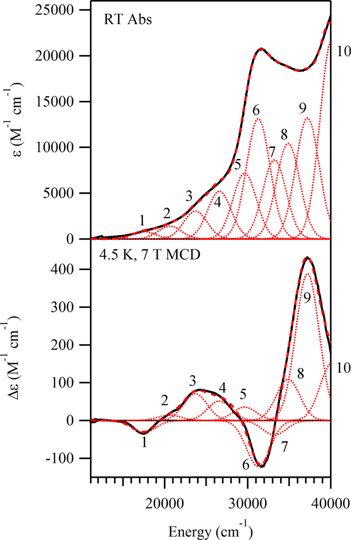
The room temperature (RT) Abs spectrum of 1 (Figure 3, top) exhibits a prominent band centered at 31 500 cm−1 (ε ≈ 20000M−1 cm−1) and a more intense feature peaking at > 40000 cm−1 (ε ≥ 25 000M−1 cm−1) as well as two shoulders located at 25 000 cm−1 (ε ≈ 5000 M−1 cm−1) and 34 700 cm−1 (ε ≈ 18 800 M−1 cm−1). In the corresponding 4.5 K, frozen solution MCD spectrum (Figure 3, bottom), four broad bands with alternating signs are observed at ∼ 17 300, 24 500, 31 600, and 37 200 cm−1. The intensities of these bands are temperature dependent (Supporting Information, Figure S1), indicating that the corresponding transitions gain MCD intensity via a C-term mechanism, as expected for a paramagnetic species like 1. To resolve the individual transitions contributing to the Abs and MCD spectra, these data were iteratively fit with the minimum acceptable number of Gaussian bands of constant width. Good agreement between the experimental and simulated spectra over the entire 11000–40 000 cm−1 range was achieved with 10 Gaussian bands (Figure 3 and Table 3). The low C/D ratios42 associated with the features observed in the Abs and MCD spectra indicate that the corresponding transitions have primarily ligand-to-metal charge transfer (LMCT) character. Specific spectral assignments are provided below.
Figure 3.
RT Abs (top) and 4.5 K 7 T MCD (bottom) solution spectra of 1 (thick black lines). Individual Gaussian bands are shown as thin dotted red lines and the simulated spectra are shown as thick dashed red lines.
Table 3.
Spectral Parameters from the Iterative Fits of the Abs and MCD Data of 1
| band | E (cm−1) |
ε (M−1 cm−1) |
Δε (M−1 cm−1) |
C/D Ratioa |
|---|---|---|---|---|
| 1 | 17515 | 814 | −31.7 | 0.037 |
| 2 | 20639 | 1401 | 14.0 | 0.010 |
| 3 | 23713 | 3033 | 71.0 | 0.022 |
| 4 | 26599 | 5216 | 51.6 | 0.009 |
| 5 | 29643 | 7178 | 35.4 | 0.004 |
| 6 | 31276 | 13132 | −121.2 | 0.009 |
| 7 | 33224 | 8626 | −38.5 | 0.004 |
| 8 | 34872 | 10425 | 109.0 | 0.010 |
| 9 | 37200 | 13207 | 388.3 | 0.028 |
| 10 | 40123 | 21716 | 150.4 | 0.007 |
C/D = (kT/βH)(Δε/ε) = 0.9576(Δε/ε) when H = 7.0T and T = 4.5K
rR Spectroscopy
On the basis of our previous study of N3-FeIIISOD,27 a single azide that is terminally bound to an iron atom will give rise to three characteristic rR features. These features are the Fe–Nazide stretch (v(Fe–N3)) located around 370 cm−1, the symmetric intra-azide stretch at ∼1350 cm−1, and the asymmetric intra-azide stretch near 2050 cm−1. Alternatively, a detailed characterization of a synthetic FeIII complex possessing two symmetry in-equivalent, cis-bound azides revealed two pairs of azide related rR features centered ∼375 and 2060 cm−1.43 These features were assigned as the v(Fe–N3) and modes associated with the two azides. Notably, no features associated with the mode were observed.
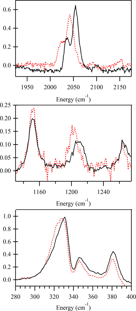
In the frozen-solution rR spectrum of 1 obtained with 20 490 cm−1 (488 nm) laser excitation, four features are observed that are sensitive to 1–15 N isotopic substitution of the coordinated azide ligands (Figure 4 and Table 5). The feature centered at 331 cm−1 is attributed to the v(Fe–N3) mode involving the coupled motion of the two azides, while the feature centered at 1210 cm−1 is attributed to the in-phase motion of the azides ligands. The remaining features at 2035 and 2055 cm−1 are assigned to the individual stretches of the two azide ligands. Examination of the rR spectrum of a solid-state sample of 2 obtained under the same conditions shows four analogous features (Supporting Information, Figure S5), indicating that the geometry of this complex in the solid state is preserved in solution. Additionally, rR spectra obtained with both lower and higher laser excitation energies (19 460 and 21 830 cm−1, respectively) show that the intensity ratio for the pair of features near 2050 cm−1 remains constant as a function of excitation energy (Supporting Information, Figures S3 and S4). It can thus be concluded that these features arise from independent stretches associated with two distinct azide ligands rather than from in-phase and out-of-phase combinations of the coupled vibrations, as in the latter scenario the in-phase combination would be preferentially resonance enhanced44 and as such the intensity ratio of the 2035/2055 cm−1 features would change as a function of excitation energy used in the rR experiment.
Figure 4.
Frozen-solution rR spectra of 1 at 77 K obtained with 20 490 cm−1 (488 nm) laser excitation. Spectra of 1 synthesized with natural abundance azide are shown in black while spectra of 1 prepared with 15N terminally labeled azide are shown as dashed, red lines. Selected regions are shown to highlight the four isotopically sensitive features arising from the stretches (top), the stretch (middle), and the v(Fe–N3) stretch (bottom). For ease of comparison the spectra have been normalized using the v(Fe–N3) peak.
Table 5.
Vibrational Frequencies (cm−1) for the Relevant Normal Modes Associated with the Azide Ligands as Obtained Experimentally for 1 and from DFT Computations using the Geometry-Optimized (1opt) and Crystal Structure Based (1xtal) Models
| DFT-Computed |
||||||||||
|---|---|---|---|---|---|---|---|---|---|---|
| Experimental (1) |
1opt |
1xtal |
||||||||
| normal mode | Fe(N3)2 | Fe(15NN2)2 | Δv | Fe(N3)2 | Fe(15NN2)2 | Δv | Fe(N3)2 | Fe(15NN2)2 | Δv | |
| 331 | 327 | 4 | 371 | 368 | 3 | 359 | 354 | 5 | ||
| 387 | 386 | 1 | ||||||||
| 1210 | 1202 | 8 | 1404 | 1392 | 12 | 1353 | 1334 | 19 | ||
| 1405 | 1396 | 9 | 1362 | 1359 | 3 | |||||
| 1368 | 1361 | 7 | ||||||||
| 1392 | 1370 | 22 | ||||||||
| 2035 | 2023 | 12 | 2199 | 2193 | 6 | 2200 | 2196 | 4 | ||
| 2055 | 2043 | 12 | 2205 | 2199 | 6 | 2229 | 2224 | 5 | ||
Computational Studies
Computational Models
To assign the observed Abs and MCD features and to obtain a quantitative bonding description for 1, electronic structure calculations were performed using two different models. The first model (1xtal) was constructed using the coordinates for one of the [FeIII(dapsox)(N3)2]1− units from the X-ray crystal structure of 2, while the second (1opt) was obtained by a DFT geometry optimization of 1xtal. As seen in Table 4, the geometry-optimized model differs from the crystallographically determined structure in two important ways: (i) the Fe–N/O(dapsox) bond lengths are significantly elongated (by up to 0.13 Å) compared to those in the crystal structure and (ii) the two axial azides have become symmetry equivalent with identical Fe–N3 bond lengths (2.04 Å) and Fe–N–N2 bond angles (129.4°). Because of these differences, the computed ground-state and excited-state properties of both models will be presented below.
Table 4.
Selected Geometric Parameters for the Different Computational Models of 1
| X-ray Crystal Structure 1xtal |
DFT Optimized 1opt |
DFT Optimized 1opt·H2O |
|
|---|---|---|---|
| Bond Lengths Å | |||
| Fe–O1 | 2.109 | 2.121 | 2.149 |
| Fe–N3 | 2.165 | 2.290 | 2.256 |
| Fe–N4 | 2.178 | 2.305 | 2.295 |
| Fe–N5 | 2.183 | 2.262 | 2.285 |
| Fe–O3 | 2.052 | 2.151 | 2.101 |
| Fe–N11 | 2.053 | 2.042 | 2.031 |
| Fe–N8 | 2.099 | 2.041 | 2.075 |
| Bond Angles (deg) | |||
| O1–Fe–N3 | 71.8 | 70.5 | 70.6 |
| N3–Fe–N4 | 70.8 | 68.6 | 68.8 |
| N4–Fe–N5 | 71.1 | 68.6 | 68.7 |
| N5–Fe–O3 | 71.9 | 70.6 | 70.5 |
| O3–Fe–O1 | 74.6 | 81.8 | 81.2 |
| N11–Fe–N8 | 175.8 | 170.2 | 171.6 |
| Fe–N11–N12 | 121.1 | 129.4 | 129.9 |
| Fe–N8–N9 | 119.0 | 129.4 | 126.4 |
| Torsion Angles (deg) | |||
| N9-N8-N11-N12 | 73.61 | 1.88 | 2.70 |
Calculated MO Diagrams
Spin-unrestricted single point DFT calculations were carried out to compute the MO energies and compositions of 1xtal and 1opt. Due to their reduced exchange-stabilization, the unoccupied Fe 3d-based spin-down MOs are higher in energy than their occupied spin-up counterparts45 and, consequently, less strongly mixed with the ligand frontier orbitals. Therefore, for ease of analysis, only the spin-down MOs will be discussed here.
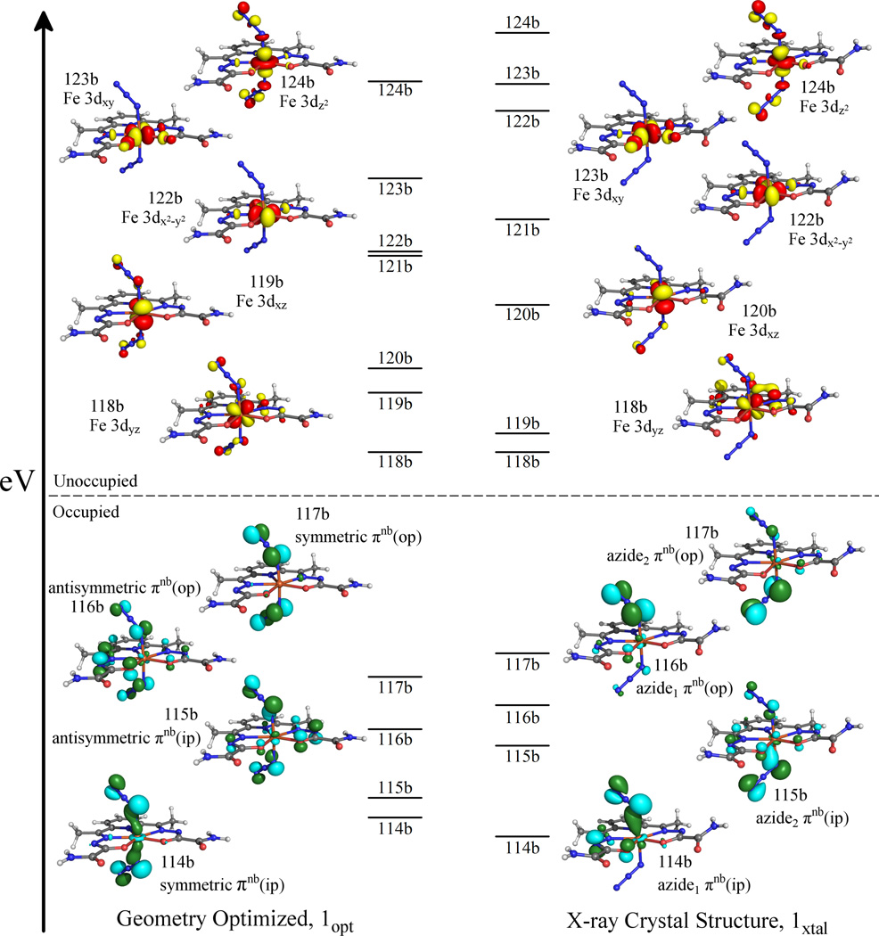
The splitting pattern of the unoccupied Fe 3d–based spin-down MOs of either model is as expected for a complex with approximate D5h symmetry (Figure 5). Lowest in energy are the Fe 3dyz (118b) and 3dxz (120b and 119b in 1xtal and 1opt, respectively) based MOs, followed by the Fe 3dx2−y2 (122b) and 3dxy (123b) based MOs and, highest in energy, the Fe 3dz2 based MO (124b). Notably, the splitting of the Fe 3d–based spin-down MOs is significantly smaller in 1opt than in 1xtal. This difference reflects the weaker Fe – dapsox antibonding interactions in 1opt as a result of the significantly larger average Fe – N/O(dapsox) bond length in this model.
Figure 5.
Energy-level diagrams of the frontier spin-down MOs, as obtained from spin-unrestricted DFT calculations on the geometry-optimized (1opt, left) and the crystal structure derived (1xtal, right) models of 1. For ease of comparison the energies of all MOs have been shifted so as to align the LUMOs. Isosurface plots of the unoccupied Fe 3d–based MOs and the occupied azide based MOs are shown to the sides.
As expected from the different orientations of the axial ligands in 1xtal and 1opt, the azide based MOs are significantly altered between the two computational models studied. Each azide ligand has two πnb orbitals, one of which is oriented in-plane (ip) and the other out-of-plane (op) with respect to the Fe–N3 plane. In 1xtal, the two azides are geometrically inequivalent and, as such, the calculated MO diagram (Figure 5) shows two sets of azide based, Fe – N3 σ- and π-bonding MOs (MOs 114b/116b and MOs 115b/117b for the upper and lower azides, respectively). Alternatively, in 1opt the azides have reoriented so as to become geometrically equivalent. Thus, both azide ligands now contribute equally to the frontier MOs; that is, the πnb (ip) and πnb (op) orbitals on the two azide are coupled either symmetrically or antisymmeterically with respect to reflection about the equatorial pseudo-mirror plane. This results in four frontier MOs of 1opt having significant azide character: the strongly Fe–N3 σ-bonding and symmetric πnb (ip) based MO 114b, the weakly Fe–N3 π-bonding and antisymmetric πnb (ip) based MO 115b, the strongly Fe–N3 π-bonding and antisymmetric πnb (op) based MO 116b, and the non-bonding, symmetric πnb (op) based MO 117b (Figure 5).
Calculated Electronic Absorption Spectra
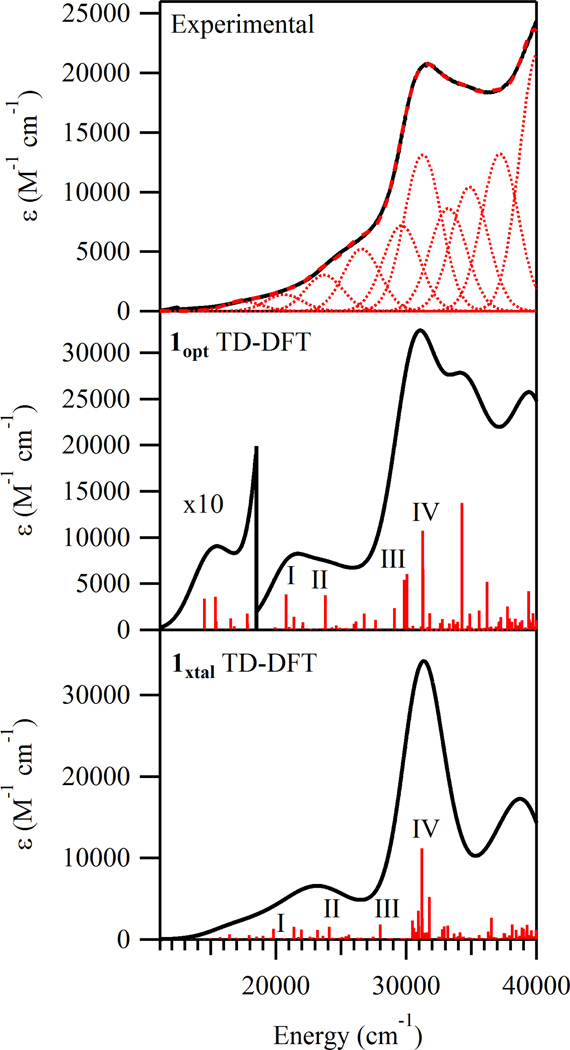
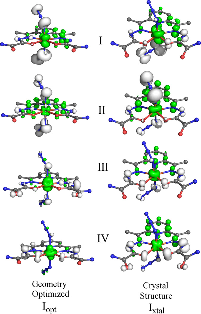
To calculate the electronic transition energies and Abs intensities for 1xtal and 1opt, TD-DFT computations were performed. In each case, the calculated Abs spectrum is in good agreement with the experimental spectrum (Figure 6). The nature of the calculated electronic transitions (e.g. ligand field, LMCT, or π → π*) was determined on the basis of electron density difference maps (EDDMs), which provide visual representations of how the electron density changes between the ground and excited states during an electronic transition. The EDDMs for the relevant transitions (identified by Roman numerals I-IV) corresponding to experimental bands 2, 3, 5, and 6, are shown in Figure 7. Examination of these plots reveals that the low energy features in the computed Abs spectra are due to charge transfer (CT) transitions that are primarily in nature. Alternatively, the transitions associated with the higher-energy bands have predominant dapsox2− → FeIII CT character. These computational predictions are consistent with the fact that the occupied MOs with significant azide character are higher in energy than those derived from the dapsox ligand (Figure 5).
Figure 6.
Experimental RT Abs spectrum of 1 (top) and TD-DFT computed Abs spectra for the 1opt and 1xtal models (middle and bottom, respectively). Selected transitions in the computational spectra are labeled with Roman numerals.
Figure 7.
EDDMs for selected TD-DFT calculated electronic transitions of 1opt (left) and 1xtal(right). White and green represent electron density loss and gain, respectively.
While the TD-DFT calculated Abs spectra for both models appear quite similar to each other and, as a whole, are in good agreement with the experimental data, a closer examination of the computational results reveals some interesting differences. First, a comparison of the EDDMs for the low-energy transitions I-III (Figure 7) indicates that the compositions of these transitions vary significantly depending on which model is used. As expected from the geometric and electronic equivalencies of the axial ligands in 1opt, transitions I-III are predicted to involve near-equal charge transfer from both of the azides to the FeIII center. Alternatively, for 1xtal these transitions have distinct contributions from the azides. Second, by comparing the high-energy region of the computed spectra (above 30 000 cm−1) it is apparent that the results for 1opt are in better agreement with the experimental data. Examination of the EDDMs for both models (Figure 7) reveals that transitions III and IV are mostly dapsox2− → FeIII CT in nature. However, in the case of 1xtal, they additionally contain a substantial amount of π → π* character. This finding, combined with the general lack of pure π → π* excitations at higher energy, indicates that the energy splitting of the the dapsox2− π and π* orbitals is somewhat underestimated in 1xtal.
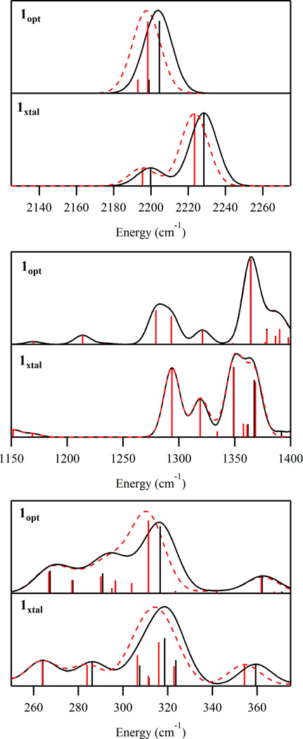
Calculated Raman Spectra
To aid in the interpretation of the experimental rR spectra of 1 and to further evaluate our computational models, additional DFT computations were performed to predict the Raman spectra of 1xtal and 1opt. As shown in Figure 8 and Table 5, both models reproduce the experimentally observed frequencies and isotopic shifts upon 14N →15 N substitution of the Fe-bound N atoms of the azides quite well for the v(Fe – N3) vibration, but to a lesser degree for the vibration. Because of the different orientations of the azide ligands in 1opt and 1xtal, the computed Raman spectra in the region of the vibration are significantly different. For 1opt, two distinct based features are predicted; however, they are separated by only 6 cm−1 while the experimental splitting is 20 cm−1. Additionally, the lower energy feature is much less intense than the higher energy one, with an intensity ratio of ∼1:5 versus ∼1:2 determined experimentally Finally, due to the symmetry equivalence of the two azides in 1opt, the lower and higher energy vibrations correspond to, respectively, the out-of-phase and in-phase combinations of the individual stretches of the two azides. Since only the in-phase combination is totally symmetric (as confirmed by the calculated depolarization ratios of 0.75 versus 0.32 for the lower and higher energy vibrations, respectively), the higher energy feature should be strongly enhanced in the rR spectrum over the lower energy one,44 an effect not observed experimentally (vide supra). In comparison with 1opt, the results obtained from the Raman calculation for 1xtal agree much better with the experimental data. Again, two stretches are calculated; however, the frequency difference of 29cm−1 and intensity ratio of ∼1:3 are much closer to the experimental values. Because in 1xtal the azides are symmetry inequivalent, each of the two calculated vibrations is associated with only one of the azides. For this reason, along with the fact that the charge transfer transitions for both azides have comparable energies (Figure 6), neither vibration would be preferentially resonance enhanced over the other, and thus, the relative rR intensities of the corresponding features should not vary substantially as a function of excitation energy. This prediction is consistent with the experimental results obtained for 1 (vide supra).
Figure 8.
Selected regions of the DFT calculated Raman spectra for models 1opt and 1xtal (upper and lower, respectively). Fe(N3) spectra are shown in black and the Fe(15NN2) spectra are shown as red, dashed lines. The vertical sticks (black and red for Fe(N3) and Fe(15NN2) , respectively) depict the energies and intensities of individual vibrations.
Effect of Intermolecular Hydrogen Bonding
As mentioned above, the inequivalence of the two azide ligands in the X-ray crystal structure of 2 likely reflects the presence of an inter-dimer hydrogen bonding interaction between the H(N7) group of dapsox of one monomeric complex 1 and the azide nitrogen N8 of another monomer. On the basis of our analysis of the MCD and rR spectra of frozen-solution samples of 2 within the framework of DFT calculations, we conclude that this inequivalence persists in solution. To evaluate the possibility that in aqueous solution N8 accepts a hydrogen bond from a water molecule, we performed an additional DFT geometry optimization for a model of 1 containing an outer-sphere water molecule (1opt ·H2O) that was originally placed at an N8…H(OH) distance of 2.30 Å (corresponding to the H(N7)…N8 distance in the X-ray crystal structure of 2). During the geometry optimization, the N8…H(OH) distance decreased to 2.02 Å, signifying a relatively strong hydrogen bonding interaction. Importantly, as summarized in Table 4, the presence of this hydrogen bond in the optimized 1opt⋅H2O model causes the two azide lig-ands to become inequivalent, with Fe–N3 bond lengths of 2.031 and 2.075Å (vs. 2.053 and 2.099 Å in 1xtal) and Fe–N–N2 bond angles of 129.9° and 126.4° (vs. 121.1° and 119.0° in 1xtal). Thus, the differences in Fe–N3 bond lengths and Fe–N–N2 bond angles observed experimentally for 1 are well reproduced in 1opt⋅H2O, lending strong support to the hypothesis that an intermolecular hydrogen bonding interaction is largely responsible for the inequivalence of the azide ligands in the solid-state structure and aqueous solutions of 2.
Discussion
As elevated cellular levels of superoxide have been implicated in a variety of diseases,13–16 the development and optimization of functional SOD mimics has recently attracted significant research interest. To improve the existing SOD mimics, it would be desirable to have a detailed knowledge of their catalytic mechanisms. However, the most promising mimics react so rapidly with that the reaction intermediates are too short lived to be trapped and characterized. As a resort, it is useful to study the interaction of SOD mimics with substrate analogues, such as the azide ion. In this study we have determined the first X-ray crystal structure of the azide adduct of one promising small molecule functional mimic of FeSOD, (Na[FeIII(dapsox)(N3)2] · DMF)2 (2). The structure of 2 reveals that upon addition of NaN3 to a solution of [FeIII(dapsox)(H2O)2]1+, both of the axial solvent ligands are replaced by azide ions, while the dapsox ligand remains coordinated in a planar, pentachelate fashion. The presence of a single sodium ion per monomeric complex 1 indicates that the dapsox ligand is doubly deprotonated, as in the case of [FeIII (dapsox) (H2O)2]1+.18,46 Interestingly, the two axial azides of 1 are inequivalent, with differing Fe – N – N2 bond angles and Fe – N3 bond lengths. Presumably, this inequivalence reflects the presences of an inter-dimer hydrogen bonding interaction involving one of the coordinated azide nitrogens, as described in the Results section.
Evaluation of our Computational Models
In the course of our studies of 1, two different computational models were considered; namely, the geometry-optimized 1opt and the crystal structure based 1xtal. These models differ in two significant ways: (i) 1opt features weaker Fe – N/O(dapsox) bonding interactions, as indicated by the increased bond lengths, and (ii) the axial azides in 1opt are symmetry equivalent and bound in a more linear fashion, with increased Fe – N – N2 bond angles of 129° vs 119° and 121° in 1xtal. An examination of the TD-DFT predicted Abs spectra reveals that both models accurately reproduce the energies and intensities of the and dapsox2− → FeIII CT transitions, though the energies of the dapsox2− π → π* transitions are somewhat underestimated with the 1xtal model. However, the calculated Raman spectrum for 1xtal is in much better agreement with the experimental results than that obtained with 1opt (see Results section).
As a major goal of this study was to obtain quantitative insight into the Fe – N3 bonding interactions in 1, the best suited computational model to consider is the one that best reproduces all of the spectral signatures of the diazide-FeIII unit. While both models successfully predict the energies and intensities of the CT transitions, only 1xtal adequately reproduces the experimentally observed rR behavior for the Vas(N3) vibrations of 1. The use of the crystal structure based model is further justified by the fact that our experimental MCD and, in particular, rR spectra are relatively unchanged when collected using either frozen solution or solid-state samples (cf. Figures 3 and S2 for the MCD spectra and Figures 4 and S5 for the rR spectra). On the basis of these considerations, we propose that the inequivalence of the two azide ligands revealed by the crystal structure of 2 persists in aqueous solution. In support of this proposal, the differences in Fe–N3 bond lengths and Fe–N–N2 bond angles observed experimentally are well reproduced in the optimized model 1opt ⋅ H2O, which features an outer-sphere water molecule at an N8…H(OH) distance of 2.02 Å (see Table 4).
Nature of Fe – N3 Bonding in 1 and Related Species
As the two πnb orbitals on each azide of 1 are oriented either in-plane (ip) or out-of-plane (op) with regards to Fe–N3 plane, they engage in distinct bonding interactions with the FeIII ion. Specifically, the πnb (ip) orbitals have significant overlap with the Fe-3dz2 orbital, leading to strong σ-bonding interactions, while the πnb (op) or-bitals are able to interact with Fe-3d based orbitals in a π -bonding fashion. This pattern of both strong σ- and π -bonding, due to the end-on, bent coordination geometry of the azide ligands, is consistent with the FeIII – N3 bonding description established previously for N3-FeIIISOD.27,29 The two Fe–N3 bonds in 1 are quite similar in terms of both their natures and strengths, which is quite different from what we found in a previous study of another diazide iron(III) complex with an FeSOD-like coordination sphere.43 In this latter complex, the two azide ligands are located cis (as opposed to trans in 1) to each other and thus engage in distinct Fe – N3 bonding interactions, with differing Fe–N–N bond angles (123.7° and 132.8°) and Fe–N3 bond lengths (1.98 Å and 2.00 Å). These differences resulted in the energies of the πnb based MOs for each azide to differ by ∼4000 cm−1, causing the appearance of two sets of CT transitions associated with the two distinct azides. As a result, in the rR spectrum of this complex the two features arising from the individual v(Fe – N3) stretches of each azide are preferentially resonance enhanced at different laser excitation energies.43
Implications for the Mechanism of SOD Catalysis
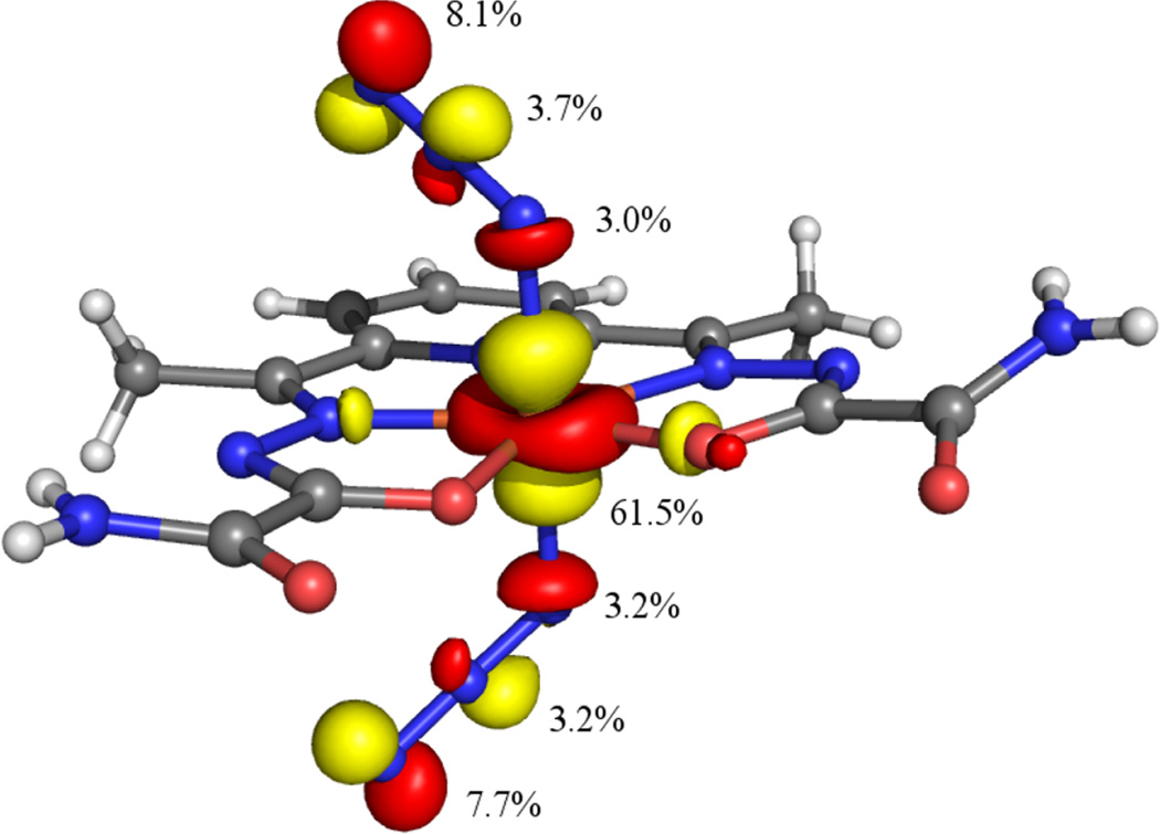
Consistent with the bonding description established for N3-FeIIISOD,27 our DFT results suggest that in 1 the FeIII-bound nitrogen atom of each azide ion carries more negative charge than the terminal nitrogen, as judged on the basis of a Loewdin atomic charge analysis. The computational prediction of larger negative charges on the coordinated versus terminal nitrogen atoms of the azide ligands is corroborated by the experimental observation of an inter-dimer H(N7)…N8 hydrogen bonding interaction in the crystal structure of 2 (see above). This prediction is also consistent with the composition of the Fe-3dz2 based spin-down MO (see Figure 9). As this orbital is unoccupied, any contributions from the azide πnb (ip) orbitals is due to delocalization of hole character from the FeIII center and reflects the degree of charge transfer within the azide πnb (ip) based, occupied MOs. In the case of the Fe-3dz2 derived spin-down MO, it is the terminal nitrogen of each azide ligand that provides the largest contribution, and thus donates the most charge to the FeIII center. This charge distribution suggests that if superoxide binds in a similar manner as azide, as expected, then (i) a large degree of electronic coupling will exist between and FeIII, thereby reducing the Frank-Condon barrier to electron transfer, and (ii) the proximal oxygen will be activated towards protonation over the terminal one. Protonation of the proximal oxygen would yield a significantly weaker Fe–hydroperoxide bond, thereby facilitating product release. The combination of these two factors is likely to play a key role with regards to the rapid reaction between [FeIII(dapsox)(H2O)2]1+ and superoxide. Notably, our results also provide indirect experimental support for the inner-sphere mechanism of disproportionation proposed previously in the literature.47
Figure 9.
Isosurface plot of the unoccupied Fe 3dz2 based spin-down MO (124b) of 1xtal. Contributions from the Fe 3d and azide N 2s and 2p orbitals are indicated.
Supplementary Material
Acknowledgement
T.C.B. thanks the National Institute of Health (GM 64631) for financial support, Dr. Frank Neese (MPI Mülheim) for providing ORCA free of charge, and one of the reviewers for pointing out the existence of an intermolecular hydrogen-bonding interaction in the crystal structure of 2. This research was supported in part by the National Science Foundation (CHE-0840494).
Footnotes
Supporting Information Available
Complete crystallographic details in CIF format; low temperature, frozen solution Abs and MCD data of 1; 4.5 and 15 K solid state MCD data of 2; frozen solution rR spectra of 1 obtained using 514 and 458 nm laser excitation; solid state rR spectrum of 2 obtained with 488 nm laser excitation; and Cartesian coordinates of 1opt, 1xtal, and 1opt ⋅ H2O. This material is available free of charge via the Internet at http://pubs.acs.org/.
References
- 1.Miller A-F, Sorkin DL. Comments on Molecular and Cellular Biophysics. 1997;9:1–48. [Google Scholar]
- 2.Fridovich I. J. Biol. Chem. 1997;272:18515–18517. doi: 10.1074/jbc.272.30.18515. [DOI] [PubMed] [Google Scholar]
- 3.Choudhury SB, Lee J-W, Davidson G, Yim Y-I, Bose K, Sharma ML, Kang S-O, Cabelli DE, Maroney MJ. Biochemistry. 1999;38:3744–3752. doi: 10.1021/bi982537j. [DOI] [PubMed] [Google Scholar]
- 4.Fridovich I. Acc. Chem. Res. 1972;5:321–326. [Google Scholar]
- 5.Bull C, Niederhoffer EC, Yoshida T, Fee JA. J. Am. Chem. Soc. 1991;113:4069–4076. [Google Scholar]
- 6.Bull C, Fee Ja. J. Am. Chem. Soc. 1985;107:3295–3304. [Google Scholar]
- 7.McAdam ME, Levelle F, Fox RA, Fielden EM. Biochem. J. 1977;165:81–87. doi: 10.1042/bj1650081. [DOI] [PMC free article] [PubMed] [Google Scholar]
- 8.Stallings WC, Pattridge KA, Strong RK, Ludwig ML. J. Biol. Chem. 1984;259:10695–10699. [PubMed] [Google Scholar]
- 9.Lah MS, Dixon MM, Pattridge KA, Stallings WC, Fee JA, Ludwig ML. Biochemistry. 1995;34:1646–1660. doi: 10.1021/bi00005a021. [DOI] [PubMed] [Google Scholar]
- 10.Yost F, Fridovich I. J. Biol. Chem. 1973;248:4905. [PubMed] [Google Scholar]
- 11.Schininà ME, Maffey L, Barra D, Bossa F, Puget K, Michelson AM. FEBS Lett. 1987;221:87–90. doi: 10.1016/0014-5793(87)80357-5. [DOI] [PubMed] [Google Scholar]
- 12.Stallings WC, Metzger AL, Pattridge KA, Fee JA, Ludwig ML. Free Radical Res. Commun. 1991;12-3:259–268. doi: 10.3109/10715769109145794. [DOI] [PubMed] [Google Scholar]
- 13.Culotta VC, Yang M, O’Halloran TV. Biochim. Biophys. Acta. 2006;1763:747–758. doi: 10.1016/j.bbamcr.2006.05.003. [DOI] [PMC free article] [PubMed] [Google Scholar]
- 14.Raha S, Robinson BH. Trends Biochem. Sci. 2000;25:502–508. doi: 10.1016/s0968-0004(00)01674-1. [DOI] [PubMed] [Google Scholar]
- 15.Simonian NA, Coyle JT. Annu. Rev. Pharmacol. Toxicol. 1996;36:83–106. doi: 10.1146/annurev.pa.36.040196.000503. [DOI] [PubMed] [Google Scholar]
- 16.Valentine JS, Wertz DL, Lyons TJ, Liou L-L, Goto JJ, Gralla EB. Curr. Opin. Chem. Biol. 1998;2:253–262. doi: 10.1016/s1367-5931(98)80067-7. [DOI] [PubMed] [Google Scholar]
- 17.Andjelković K, Bacchi A, Pelizzi G, Jeremić D, Ivanović-Burmazović I. J. Coord. Chem. 2002;55:1385–1392. [Google Scholar]
- 18.Liu G-F, Filipović M, Heinemann FW, Ivanović-Burmazović I. Inorg. Chem. 2007;46:8825–8835. doi: 10.1021/ic7012039. [DOI] [PubMed] [Google Scholar]
- 19.Gutman CT, Brunold TC. Inorg. Chem. 2012;51:12729–12737. doi: 10.1021/ic301547z. [DOI] [PMC free article] [PubMed] [Google Scholar]
- 20.Whittaker MM, Whittaker JW. Biochemistry. 1996;35:6762–6770. doi: 10.1021/bi960088m. [DOI] [PubMed] [Google Scholar]
- 21.Vance CK, Miller, a F. Biochemistry. 1998;37:5518–5527. doi: 10.1021/bi972580r. [DOI] [PubMed] [Google Scholar]
- 22.Miller A-F, Sorkin DL, Padmakumar K. Biochemistry. 2005;44:5969–5981. doi: 10.1021/bi0476331. [DOI] [PubMed] [Google Scholar]
- 23.Tierney DL, Fee JA, Ludwig ML, Penner-Hahn JE. Biochemistry. 1995;34:1661–1668. doi: 10.1021/bi00005a022. [DOI] [PubMed] [Google Scholar]
- 24.Slykhouse TO, Fee JA. J. Biol. Chem. 1976;251:5472–5477. [PubMed] [Google Scholar]
- 25.Misra HP, Fridovich I. Arch. Biochem. Biophys. 1978;189:317–322. doi: 10.1016/0003-9861(78)90218-7. [DOI] [PubMed] [Google Scholar]
- 26.Jackson TA, Karapetian A, Miller A-F, Brunold TC. J. Am. Chem. Soc. 2004;126:12477–12491. doi: 10.1021/ja0482583. [DOI] [PubMed] [Google Scholar]
- 27.Xie J, Yikilmaz E, Miller A-F, Brunold TC. J. Am. Chem. Soc. 2002;124:3769–3774. doi: 10.1021/ja016254h. [DOI] [PubMed] [Google Scholar]
- 28.Whittaker JW, Whittaker MM. J. Am. Chem. Soc. 1991;113:5528–5540. [Google Scholar]
- 29.Grove LE, Xie J, Yikilmaz E, Karapetyan A, Miller A-F, Brunold TC. Inorg. Chem. 2008;47:3993–4004. doi: 10.1021/ic702414m. [DOI] [PMC free article] [PubMed] [Google Scholar]
- 30.Bruker-AXS. APEX2, SADABS, and SAINT Software Reference Manuals. Madison, WI USA: Bruker-AXS; pp. 2007–2011. [Google Scholar]
- 31.Neese F. ORCA 2.9.1, An Ab Initio, DFT and Semiempirical electronic structure package. 2012 [Google Scholar]
- 32.Becke AD. J. Chem. Phys. 1993;98:5648. [Google Scholar]
- 33.Becke AD. J. Chem. Phys. 1993;98:1372. [Google Scholar]
- 34.Lee C, Yang W, Parr RG. Physical Review B. 1988;37:785. doi: 10.1103/physrevb.37.785. [DOI] [PubMed] [Google Scholar]
- 35.Schaer A, Horn H, Ahlrichs R. J. Chem. Phys. 1992;97:2571. [Google Scholar]
- 36.Weigend F, Häser M. Theoretica Chimica Acta. 1997;97:331–340. [Google Scholar]
- 37.Schaer A, Huber C, Ahlrichs R. J. Chem. Phys. 1994;100:5829. [Google Scholar]
- 38.Hirata S, Head-Gordon M. Chem. Phys. Lett. 1999;314:291–299. [Google Scholar]
- 39.Hirata S, Head-Gordon M. Chem. Phys. Lett. 1999;302:375–382. [Google Scholar]
- 40.The PyMOL Molecular Graphics System, L. Version 1.5.0.1 Schrodinger [Google Scholar]
- 41.Frisch MJ, Trucks GW, Schlegel HB, Scuseria GE, Robb MA, Cheeseman JR, Scalmani G, Barone V, Mennucci B, Petersson GA, Nakatsuji H, Caricato M, Li X, Hratchian HP, Izmaylov AF, Bloino J, Zheng G, Sonnenberg JL, Hada M, Ehara M, Toyota K, Fukuda R, Hasegawa J, Ishida M, Nakajima T, Honda Y, Kitao O, Nakai H, Vreven T, Montgomery JA, Jr, Peralta JE, Ogliaro F, Bearpark M, Heyd JJ, Brothers E, Kudin KN, Staroverov VN, Kobayashi R, Normand J, Raghavachari K, Rendell A, Burant JC, Iyengar SS, Tomasi J, Cossi M, Rega N, Millam JM, Klene M, Knox JE, Cross JB, Bakken V, Adamo C, Jaramillo J, Gomperts R, Stratmann RE, Yazyev O, Austin AJ, Cammi R, Pomelli C, Ochterski JW, Martin RL, Morokuma K, Zakrzewski VG, Voth GA, Salvador P, Dannenberg JJ, Dapprich S, Daniels AD, Farkas Ö, Foresman JB, Ortiz JV, Cioslowski J, Fox DJ. Gaussian 09 Revision C.01. Wallingford CT: Gaussian Inc; 2009. [Google Scholar]
- 42.The C/D ratio is defined as (kT/βH)(Δε/ε) and is equal to 0.9576(Δε/ε) when H = 7.0 T and T = 4.5 K. This ratio provides a measure of the relative intensity of an electronic transition between the MCD and Abs spectra. Larger ratios are associated with ligand field transitions while smaller ratios are typically observed for charge transfer and π → π* transitions
- 43.Grove LE, Hallman JK, Emerson JP, Halfen JA, Brunold TC. Inorg. Chem. 2008;47:5762–5774. doi: 10.1021/ic800073t. [DOI] [PMC free article] [PubMed] [Google Scholar]
- 44.Spiro TG, Czernuszewicz RS. Chapter Resonance Raman Spectroscopy. In: Lawrence Que J, editor. Physical Methods in Bioinorganic Chemistry. University Science Books; 2000. pp. 59–119. [Google Scholar]
- 45.Li J, Noodleman L, Case DA. Chapter Electronic Structure Calculations; Density Functional Methods with Applications to Transition Metal Complexes. In: Solomon EI, Lever A, editors. Inorganic Electronic Structure and Spectroscopy. Vol. 1. New York: John Wiley & Sons, Ltd; 1999. p. 669. [Google Scholar]
- 46.Sarauli D, Meier R, Liu G-F, Ivanović-Burmazović I, van Eldik R. Inorg. Chem. 2005;44:7624–7633. doi: 10.1021/ic0507767. [DOI] [PubMed] [Google Scholar]
- 47.Ivanović-Burmazović I, Filipović MR. In: Advances in Inorganic Chemistry. van Eldik R, Ivanović-Burmazović I, editors. Vol. 64. Academic Press; 2012. pp. 53–95. Chapter 3. [Google Scholar]
Associated Data
This section collects any data citations, data availability statements, or supplementary materials included in this article.


