

Abstract
Detailed understanding of the nature of the active centers in non-precious-metal-based electrocatalyst, and their role in oxygen reduction reaction (ORR) mechanistic pathways will have a profound effect on successful commercialization of emission-free energy devices such as fuel cells. Recently, using pyrolyzed model structures of iron porphyrins, we have demonstrated that a covalent integration of the Fe–Nx sites into π-conjugated carbon basal plane modifies electron donating/withdrawing capability of the carbonaceous ligand, consequently improving ORR activity. Here, we employ a combination of in situ X-ray spectroscopy and electrochemical methods to identify the various structural and functional forms of the active centers in non-heme Fe/N/C catalysts. Both methods corroboratively confirm the single site 2e– × 2e– mechanism in alkaline media on the primary Fe2+–N4 centers and the dual-site 2e– × 2e– mechanism in acid media with the significant role of the surface bound coexisting Fe/FexOy nanoparticles (NPs) as the secondary active sites.
1. Introduction
The replacement of Pt and Pt alloys with non-precious-metal-based catalysts for oxygen reduction reaction (ORR) is considered the Holy Grail for electrocatalysis-related efforts.1 Most early studies were primarily focused on pyrolysis of macrocycles containing an existing metal–nitrogen (M–N4) center.2−5 Later, however, it was found that starting from precursors that do not contain an existing M–N4 moiety also results in relatively high ORR activity.6−10 The principal distinction between those prepared from pyrolysis of existing M–N4 moieties and aforementioned reports of more recent vintage, where active sites evolve based on choice of appropriate precursors and pyrolysis conditions, is the nature of the evolved active site resulting in significant reduction of overpotential in ORR activity for the latter.5,9,11,12
Considering the most recent progress, where active sites are evolved using precursor materials with no existing M–N4 coordination, several classes of synthetic approaches have emerged in terms of materials strategies requiring diverse combinations of metal–nitrogen–carbon (MNC) precursors and pyrolysis conditions. These include (1) reactive polymer approach (such as those using polyaniline9 or polyethylenimine13), (2) small chelating compounds (i.e., pyridine,14 aminoantipyrine,15−19 phenanthroline20), or (3) active-nitrogen carrying gas molecules such as ammonia.20 Each of these approaches has shown very promising activity for ORR.8,10,15,22 However, based on the aforementioned progress toward higher ORR activity, it is imperative to elucidate fundamental questions such as (a) what is the role of the transition metal in ORR activity, (b) is the ORR active site a singular or bifunctional in nature, and (c) considering the success reported in engendering active ORR catalysts with such pluralistic use of precursor materials, is there a common active site for all these diverse materials or do they represent a cornucopia of diverse active sites? Hence, understanding the nature of the active site and the origin of ORR activity on these materials is critically needed to expedite the process for achieving activity close to 1/10th of the Pt/C mass activity (A/gPt)23 and stability targets (5000 h).24
Despite some speculations that there is no need for presence of the metal centers for the initiation of oxygen reduction process,25−27 a current number of reports unequivocally point toward the critical importance of metal–nitrogen coordinated sites M–Nx (in most cases M = Fe)8,28−31 essentially embedded within the microporous skeleton of the carbon scaffold of non-PGM catalysts8 when the metal center is coordinated with pyridinic5,31 or pyrrolic32 nitrogen atoms.
Recently,33 we have shown Fe–N centers in pyrolyzed metal macrocycles with ORR activity governed by the metal–oxygen interaction in a similar fashion to the unpyrolyzed heme centers, where the initial oxygen adsorption on metal cation is directly related to its redox transition.34−39 Here, for the first time we show a corroborative multiple-source data that confirms the formation of Fe–N4 moieties upon pyrolysis of various non-N4 consisting materials. Similar to the biomimetic heme moieties, the Fe–N4 center undergo Fe2+/Fe3+ redox transition which strongly relates to the initiation step of the oxygen reduction process. In alkaline electrolyte, the pyrolytically derived metal–nitrogen coordinated Fe–Nx–C centers catalytically convert molecular oxygen to water30 as a result of an optimal stabilization of peroxide anion (HO2–) intermediate on the metal–nitrogen coordinated sites with the entire 4e– reduction occurring as a single-site process on the Fe2+–Nx center.30 On the contrary, it is shown here that while the primary Fe2+–Nx active site is still responsible for the initiation of oxygen reduction to hydrogen peroxide (H2O2) molecular intermediate in acid electrolyte, there is a need for secondary active centers adjacent to the Fe2+–Nx sites to complete the 4e– process due to the poor stabilization of H2O2 molecular intermediate on the Fe2+–Nx sites. As the recent group of transition-metal-based catalyst derived from non-N4 precursors facilitate overall 4e– ORR mechanism with high onset potential, the pluralistic nature of their catalytic sites becomes increasingly favored. Olson et al.,40 as one of the first, proposed a bifunctional mechanism presenting evidence favoring two-step ORR pathways with the second step occurring on the metal nanoparticles coated with a thin layer of their native oxides (M/MxOy).40 Considering the possible of lack of stability of the transition metal nanoparticles and their oxides in an acidic environment, the role of the M/MxOy as secondary active sites has been widely challenged.41 According to the most recent evidence,9,28,42 however, the best to date performing Fe–Nx–C catalysts consist of some forms of metal nanoparticles and/or their oxides (Fe0/FexOy) which stay intact even after several acid washing and exposure to hours-long electrochemical experiments in acidic pH. This durability has been attributed to the presence of protective graphene-like layers surrounding the metal nanoparticles,9,43 with a possible direct role in enhancing the ORR activity.9,28,42 To this day, however, there is no coherent data unanimously supporting this hypothesis as most of the methods reported in prior literature involved the use of ex situ techniques, such as X-ray photoelectron spectroscopy (XPS).41,44,45 Very limited work has been based on in situ studies of physical and electronic properties of the Fe–N–C catalysts, which often change largely under working conditions.33,35,46−48 Here, we use element-specific in situ XAS as a tool to effectively connect electrochemical data with site specific ORR pathways and mechanisms. We report for the first time incontrovertible experimental evidence of (a) the need for bifunctional active sites for ORR in acidic pH in contrast to (b) a single site process in alkaline conditions and (c) the evolution of common active sites on nonprecious catalysts across several laboratories with the same genesis derived using diverse approaches and precursor materials.
2. Results and Discussion
2.1. ORR Activity in pH 1 Electrolyte
Figures 1a,b show a comparative ORR activity analysis on several Fe–Nx–C catalysts pyrolytically synthesized across various laboratories. This was accomplished using diverse precursors such as poly(N-vinylamine guanidine) (PVAG), poly(ethylene imine) (PEI), aminoantipyrine (AAPyr), and varied synthetic methodologies such as the reactive polymer approaches (Materials Preparation section) on standard carbon support and the sacrificial support method.15 Despite the different synthesis procedures and precursors employed, each of these materials facilitate ORR at close range of onset potentials (∼0.85–0.87 V vs RHE). The variations in diffusion-limited current densities are a result of differences in density, nature, and distribution of the available active centers in the high surface area microporous carbon scaffolds. The observation of similar Tafel slopes with values in the range of 56–63 mV/decade (Figure 1 (inset) and Supporting Information Table S1) is suggestive of a common rate-limiting step (RDS) involving one-electron transfer.55 However, such a rudimentary interpretation is predicated on fact that this data is derived from high loading of catalysts, hence relatively lower active site density in an otherwise thick electrode necessitating an in-depth fundamental understanding of the catalyst structure and reaction mechanisms using other complementary methodologies. Even though the presence of a redox behavior in similarly derived group of catalysts has been proposed earlier,23 here we show using a combination of both electrochemical and element-specific spectroscopic results a clear corelation between the redox transiton and onset of ORR. As observed in Figure 1b, initiation of ORR is strongly correlated to the Fe2+/Fe3+ redox transition of the Fe–Nx moiety corraborated by the Fe K-edge XANES results discussed below.20,28,30,31 Here we confirm not only presence of these moieties but more importantly direct involvement in catalytic initiation of ORR process in a similar fashion as in heme centers present in nonpyrolyzed N4-type structures (metal porphyrins and metal phthalocyanines)36−38 described via reaction 1-1:
| 1-1 |
Figure 1.
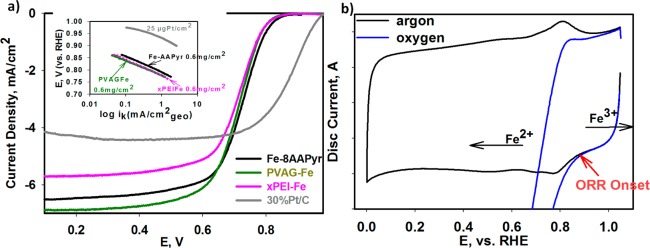
Electrochemical study of UNM Fe-8AAPyr, NEU PVAG-Fe, and xBPEIFe compared to BASF-ETEK 30% Pt/C in 0.1 M HClO4. (a) ORR polarization curves, with Tafel slopes in the inset, collected at 1600 rpm. (b) A typical for Fe–NC catalysts CV in O2-free (black) electrolyte with the clear Fe2+/Fe3+ redox transition between 0.7 and 0.9 V and corresponding ORR polarization curve (blue) collected with PVAG-Fe catalyst. Scan rate: 20 mV/s. Loading of FeNC catalysts: 0.6 mg/cm2 on 5.61 mm glassy carbon disk electrode. Loading of Pt/C: catalyst 25 μgPt/cm2.
2.2. Chemical Forms and Structure of the Iron Centers and Their Activity
Forms of iron centers present in the Fe–Nx–C catalysts and their behavior were studied using in situ (XAS). While the coordination number of the iron center and type of direct neighboring atoms can be identified by Fourier transform (FT) of the extended XAS fine structure (EXAFS), the X-ray absorption near-edge spectral (XANES) region permits monitoring any changes in oxidation state of these metal centers and the nature of surface adsorbates (though surface sensitive Δμ technique56) as a function of alterations in experimental conditions. Consistent with the earlier observations regarding metal-coordinated functionalities in high temperature pyrolyzed materials, each of the analyzed Fe–Nx–C catalysts including FeAAPyr,15,16,18,19 PVAG-Fe, and additionally PANIFeCo developed at Los Alamos National Laboratory9 consists of two types Fe moieties (Figure 2a–c), namely, the metal–nitrogen coordinated centers of the form Fe–N4 and Fe/FexOy nanoparticles (NPs). The secondary Fe–Fe FT XAS peaks well overlap with the spectra of standard metallic iron foil, suggesting that these peaks originate mainly from the Fe–Fe scattering in iron nanoparticles, FeNPs (Figure 2a–c). The Fe–Nx could be fitted only with the Fe–N4 model structures formed by covalent incorporation of Fe–N4 active sites in divacant defects on the carbon basal plane (Supporting Information Table S2) similarly to the Fe–N centers present in carbon-supported pyrolyzed Fe-porphyrin discussed in our earlier work.33 Meanwhile, the peak at ∼2.8 Å indicates the presence of a small amount of iron oxides (FexOy). It is important to note that these secondary peaks related to the nanoparticles are present in all of the analyzed Fe–Nx–C catalysts and stay intact during the whole experimental process (typically between 12 and 30 h) under standard conditions in acid electrolyte (pH 0–1 while applying potential bias between 0 and 1 V vs RHE).
Figure 2.
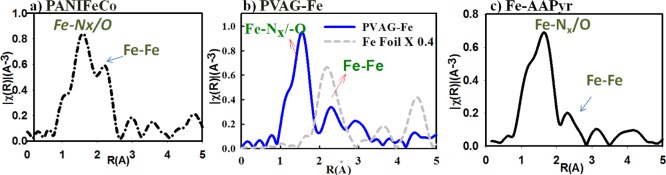
Fourier transform (FT) EXAFS of (a) LANL PANIFeCo compared with (b) PVAG-Fe and (c) UNM Fe-AAPyr catalysts collected on Fe-edge (7112 eV) in O2-saturated 0.1 M HClO4. Part b consists of in situ Fe K-edge PVAG-Fe EXAFS spectra compared with metallic Fe-foil (black) as standard. The main peak around 1.5 Å represents Fe–Nx form of the metal. The low intensity peaks above 2 Å and above 4 Å represent Fe–Fe bond, indicating the presence of Fe-nanoparticles in the heat-treated catalyst (green). Note: all the radial distances given in this work are without phase correction.
As shown in Figure 3a, the potential dependent shift to higher energies in Fe K-edge XANES spectra of typical Fe–Nx–C catalyst coupled with the electrochemical redox transition in the range 0.7–0.9 V (Figure 3a, inset) indicates the change in oxidation state of the iron metal center recently observed by Ferrandon et al.57 The Fe K-edge shift increases until reaching maximum of ∼2.5 eV at 0.9 V (vs RHE) consistent with a net oxidation state change of a single electron per iron site implying a the redox transition of Fe2+–N4 to Fe3+–N4.58 This coupled electrochemical and spectroscopic result along with the ORR polarization curves shown in Figure 1 unambiguously evidence the direct involvement of the metal center redox transition in the catalytic initiation of oxygen reduction process. Concomitant to the oxidation state change from Fe2+–N4 to Fe3+–N4, there is also a corresponding formation of oxygenated adsorbates (O–Fe3+–Nx) which is observed here in Figure 3b based on increase in intensity of the FT XAS peak at ∼1.5 Å at potentials above 0.7 V and attaining a maximum at 0.9 V vs RHE. This is also detected by surface sensitive Δμ methodology of the XANES spectra shown in Figure 4a in the form of increased amplitude of the primary negative peak at 7126 eV when the potential bias exceeds 0.7 V (vs RHE). The oxygenated adsorbates on the Fe3+–N4 center shows no further increase at potentials higher than 0.9 V, suggesting full coverage of the catalytic Fe–N4 surface by the oxygenated species. By linking the fully covered Fe–N4 surface with the ORR onset (0.9 V, consistent with tail of the redox transition shown in Figure 1), one can conclude that the Fe–N4 sites become occupied by hydroxyl species (OH–), originating from water activation (reaction 1-2), blocking actives sites from the molecular oxygen adsorption. Alternately, this implies that molecular O2 competes for Fe–N4 active sites with the oxygenated species formed via water activation. This is a well-known phenomenon involving platinum-based catalysts, where water activation is one of the main causes known for ORR overpotentials.59−61
| 1-2 |
Here the oxidation state of the Fe–N center determines availability of the catalytic surface for the adsorption of molecular oxygen. This is governed by optimized binding energies between the Fe center and O2 and/or other nucleophilic species present in the system (including OH– originating from water activation). The iron 2+ oxidation state ensures efficient adsorption/desorption of the O2, ORR intermediates, and/or products. Our in situ observations of the Fe/electrolyte interface undoubtedly confirm that in case of the Fe3+–N4 the adsorption energy between Fe–O (O2, OH–, O2H–) is too large, resulting in poisoning the active Fe–N surface. One-electron reduction of the pentacoordinate HO–Fe3+–N4 site to the square-planar Fe2+–N4 active site which is devoid of any oxygenated water activation species on the axial position ensures initial molecular adsorption of molecular oxygen on the active site.32,33,62 This is the first time, however, where we show a clear experimental proof observed spectroscopically and electrochemically.
Figure 3.
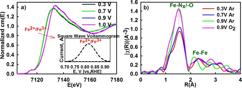
(a) Potential dependent normalized Fe K-edge XANES spectra with corresponding redox peak transition shown in inset as a background-subtracted square wave voltammetry profile collected in oxygen-free 0.1 M HClO4. (b) Fourier Transform of the extended region of the XAS spectra collected in situ at Fe K-edge (7112 eV) of PVAG-Fe catalyst.
Figure 4.
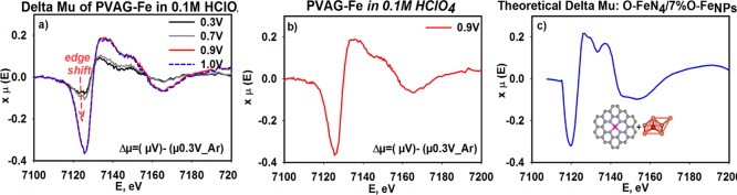
(a) Δμ spectra of PVAG-Fe collected in situ at Fe K-edge representing changes on the Fe-surface through the range of potentials due to metal interaction with oxygenated adsorbates. (b) Experimental Δμ of fully covered active surface (in this case attained at 0.9 V) compared to (c) the theoretical model consisting of 93% FeN4C10–O and 7% O–FeNPs. Experimental Δμ signatures were obtained by subtracting the XANES signatures according to Δμ = μ(0.90 V) – μ(0.30 V). More detailed information on the methodology used to obtain the theoretical model is given in the Supporting Information (Figure S3).
Contribution of the XANES and FT EXAFS signals of the minor FeNPs/C form is likely overshadowed with the majority of the Fe–N moieties. Considering this limitation, the catalytic participation of the metal nanoparticles (earlier detected by FT EXAFS spectra) was investigated by verifying any surface interactions of the FeNPs/C with adsorbates through employment of the subtractive Δμ technique. The increase in amplitude of the Δμ spectra of the PVAG-Fe catalyst as a function of potential (Figure 4a) is a result of the interaction of both Fe-centers (Fe–N4C and FeNPs/C) with adsorbates (O2, O(H), O2H–). This was confirmed with the model Δμ signature build as a linear combination of 93% FeN4C10 and 7% FeNPs contents (Figure 4b,c) as described in the Supporting Information (Figure S4). The maximum in amplitude of both the negative and the positive Δμ peaks (Figure 4a) was attained at 0.9 V with no further changes above this potential as the active surface become fully covered by the adsorbates.
2.3. Oxygen Reduction Mechanistic Functionality of Fe–N4/C and FeNPs/C Centers
The distinct functions of the FeNPs/C and Fe–N4–C were elucidated by monitoring changes in ORR activity and mechanistic pathways as result of selective removal or inhibition (poisoning effect) of one type of metal center at a time. The selective inhibition of the Fe–N centers was achieved with addition of cyanide anions (CN–), a well-known poison, to biomimetic Fe–N4 centers with high selectivity of forming very strong complexes with the oxidized form of the iron center (3+ oxidation state).63 Additionally, the selective removal of the FeNPs moieites was based on treatment of the catalyst to voltammetric cycling while immersed in hydrogen peroxide containing acidic electrolyte (see Experimental Section). Hydrogen peroxide is known to decompose in an acidic environment, especially in the presence of iron, to form highly reactive •OH and •OOH radicals. Peroxide radicals formed due to production of H2O2 as ORR byproduct are known to cause corrosion of carbon-supported catalytic metals in working fuel cell environment, resulting in irreversible dissolution of the metal particles.64,65 A similar effect was expected here, upon external introduction of hydrogen peroxide. This, in reality, fairly slow process was accelerated by employing relatively large amounts of H2O2 and applying corrosive potentials. This treatment was expected to cause dissolution of the FeNPs through damage of their protective layers of the carbonaceous scaffold. As shown in Figure 5, removal of these nanoparticles proved by FT EXAFS (Figure 5c, significant reduction of the secondary peak at ∼2 Å corresponding to the Fe–Fe bonding in Fe/FexOy with intact Fe–N4 peak) results in a substantial decrease of ORR activity in acidic environment (Figure 5a) with increased (proportional to the distortion level) production of peroxide intermediate (Supporting Information, Figure S2a,b). Contrarily, no detectable impact of the selective removal step is observed on ORR performance in alkaline electrolyte (Figure 5b), which is consistent with our earlier report that in alkaline environment the entire 4e– reduction process occurs on a single Fe–N4 active site. As shown in Figure 6a, the peroxide treatment removed only the NPs form of metal, leaving the nitrogen coordinated metal cation intact. This result is in corroboration to the effect of cyanide poisoning of the Fe–N centers. It was earlier presented that the cyanide anions are able to poison Fe–N centers in pyrolyzed N4 macrocycles in alkaline electrolyte.66 Here, we demostrate that the CN– causes ORR inhibition in both ranges of pH, acid and alkaline. Introduction of CN¯ resulted in impaired ORR activity in both media by shifting ORR polarization curves toward the negative potentials (Figure 6). Further, while the CN– poisoning did not affect overall mechanism of ORR in acid (Figure 6a–c), a clear change from 4e– to 2e– ORR pathway was observed in alkaline (Figure 6b–d), which is demonstrated with the positive shift of the ring oxidation onset, once again clearly confirming the function of the Fe–N4 center as primary active site in both media. This behavior results from blocking the primary Fe–N4 center responsible for 4e– oxygen reduction, leaving only the active sites (i.e., nitrogen-doped carbon present in the MNC structure) with capability to form hydrogen peroxide through the two pathways. The negative shift of polarization curve along with the unaltered nature of the mechanism in the acid pH upon cyanide addition (Figure 6a–c) suggests that, like in the natural heme structures, the CN– strongly interacts only with the Fe3+ form of the Fe–N4 center, hindering its back-reduction to the Fe2+ state (represented as slight negative shift of the redox peak shown in the inset of Figure 6a) and consequently suppressing initiation process of the ORR in both media.
Figure 5.
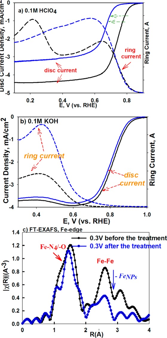
Destructive effect of peroxide treatment represented by ORR RRDE curves of the PVAG-Fe catalyst in 0.1 M HClO4 (a) and in 0.1 M KOH (b), initially (—) and after destructive treatment (- - -). Scan rate: 20 mV/s. Loading of FeNC catalysts: 0.6 mg/cm2 on 5.61 mm glassy carbon ring disk electrode. (c) FT EXAFS Fe-edge spectra of PVAG-Fe catalyst before (black) and after (blue) the treatment.
Figure 6.
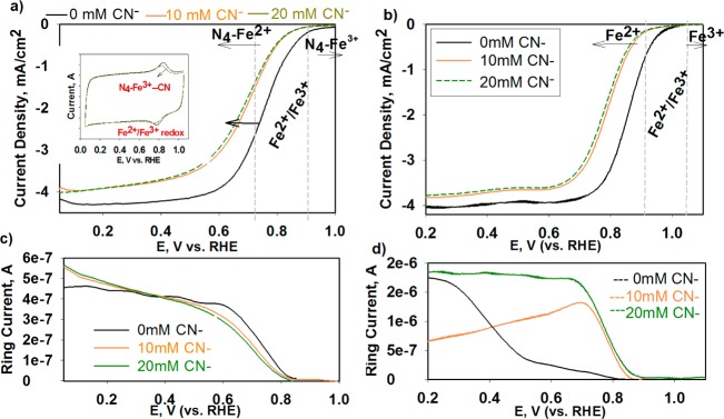
Effect of CN– poisoning of Fe–N4 center in the xPEI-Fe catalyst: Polarization curves and ring currents in 0.1 M HClO4 (a–c) and 0.1 M KOH (b–d), respectively. RRDE: RHE ref, Au-GC 0.2472 cm2, 900 rpm, 20 mV·s and 0.6 mg/cm2 catalyst loading, at 0, 10, and 20 mM KCN. The inset in (a) shows Fe2+/Fe3+ redox with and without presence of the CN anions in cyclic voltammogram collected in O2-free 0.1 M HClO4. RDE: RHE ref, Au-GC 0.247 cm2, 20 mV·s. Introduction of the CN– results in noticeable shift of the back reduction of the Fe3+ to Fe2+ due to formation of Fe3+–CN– complexes.
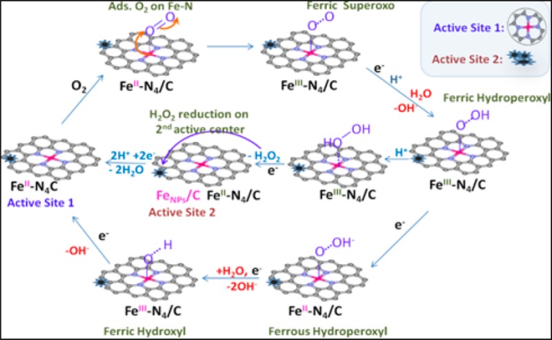
This catalytic behavior resulting in selective “blocking” of the two forms of the metal centers provides us with convincing evidence that the stabilized form of metal nanoparticles play an important role in ORR activity in acid.28 Moreover, it provides the first experimental proof of the two-site 2e– × 2e– ORR mechanism in acid earlier proposed40 and single site pathways in alkaline discussed in our recent paper33 (Figure 7).
Figure 7.

Proposed ORR mechanistic pathways on Fe–N4/C and adjacent FeNPS/C in acidic (H+) and alkaline (H2O/–OH) electrolyte.
3. Conclusion
In the present work, we have generated a structure-to-function relationship of the iron moieties present in Fe–Nx–C-type catalysts synthesized by high temperature pyrolysis of various metal–nitrogen–carbon precursors across various laboratories. We were able to verify that despite the variety of precursors and their synthetic pathways used, the final activation step involving the thermal treatment leads to alike ORR active metal centers on carbonaceous surfaces, including Fe cations coordinated by pyridinic nitrogen atoms conforming to the earlier proposed Fe–N4/C sites and very durable forms of metal nanoparticles (FeNPs/C). The Fe–N4 centers (often also defined as Fe–N2+2) have characteristic redox features at potentials fairly close to thermodynamic potential of oxygen reduction which is the main reason for the ORR activity of this type of sites where the Fe center ought to be in +2 oxidation state to ensure availability of an optimal active sites for ORR activation and the subsequent processes. Similarly to the heat-treated porphyrins with pre-existing Fe–N4 moiety,33 the redox feature, occurring at unusually high potentials, is ensured by imbedding the Fe–N4 center within π-electron-deficient graphitic carbon ligand environment, resulting in a significant modification in the electron density and energy level of the eg-orbital (dz2) of the transition metal ion.
In both ranges of pH, the Fe–N site is involved in the ORR initiation process of O2 adsorption on the primary Fe2+–N4 site, and 2e– reduction to peroxide intermediate. In alkaline pH the subsequent electroreduction of HO2– intermediate proceeds on the same Fe2+–N4 active center to yield the overall 4e– ORR mechanism. On the contrary, in acid media the H2O2 intermediate needs a secondary active sites, in this case FeNPs/C, which situated at close proximity to the primary Fe–N4 centers to ensure the subsequent reduction to the 4e– product or else the peroxide intermediate desorbs into electrolyte resulting in only an overall 2e– ORR mechanism. The detailed form of these active iron nanoparticles is not yet well understood. Based on our in situ XAS observations, including Fe–Fe bond distances correlated with overall activity of these catalysis, the active form of the Fe NPs is metallic form. However, the optimal NPs form has to be further studied. Based on our observations, these nanoparticles play an important role in ORR activity. Their detailed function however is still under question. It is possible that the metal particles act as dopants, which change electronic structure of the neighboring atoms, perhaps carbon or nitrogen, activating the last toward oxygen reduction.
A careful synthetic prearrangement of active centers in the non-N4/C precursors results in formation of graphitic structure consisting of bifunctional active sites Fe–N/C and FeNPs/C, upon the heat treatment, with the letter being of special importance in the acidic media. Our experimental data provide undeniable evidence of the synergistic effect of the surface bound uncomplexed form of metallic Fe nanoparticle centers as part of the active surface which enables faradaic reduction of peroxide intermediate resulting in the 2e– × 2e– mechanism in acidic electrolyte. The overall activity of such materials strictly depends on density of the available active sites and their durability. The recent methodologies have proven the first with still some room for the latter. The work presented here however should leave no doubts whether or not the transition metal is important to obtain the best performance of this group of materials. Further, understanding the distinct functions of these two types of metal center in both ranges of pH provide us with an important guidance of how to tailor synthesis processes of these materials to obtain optimal surface properties for specific applications.
4. Experimental Section
All mechanistic studies presented in this work were performed on in-house developed Fe–Nx–C catalysts pyrolytically synthesized using poly(N-vinylamine guanidine) (PVAG) and cross-linked poly(ethylene imine) networks (xPEI) based on nitrogen/oxygen containing metal complexing polymeric precursors. Other Fe–Nx–C catalyst provided by our collaborative laboratories, including PANIFeCo9 developed by Los Alamos National Laboratory (LANL) and Fe-AAPyr19 by the University of New Mexico (UNM), were studied as well to verify the common structural and functional nature of the metal centers present in these class of non-precious-metal catalysts. In situ X-ray absorption spectroscopy was employed to identify the various structural and electronic forms of iron centers present in these non-precious-metal catalysts. Data collection and analysis of the extended (EXAFS) and near (NEXAFS) structure including the subtractive Δμ technique.
Materials Preparation
Synthesis of the PANIFeCo is described elsewhere.9 Briefly, prior to pyrolysis, the PANIFeCo precursor is prepared from polyaniline (PANI) prepolymer supported on carbon black and further polymerized in the presence of iron and cobalt salts.9 The Fe-AAPyr catalyst is prepared by pyrolysis of silica templated aminoantipyrine (AAPyr) as N-precursor and Fe-salt and removal of the sacrificial support after the heat treatment resulting in open-structured MNC network.15 The PVAG-Fe catalysts was prepared by pyrolysis of the prior synthesized poly(vinylamine guanidine)–Fe complex (PVAG-Fe) supported on functionalized carbon black (Ketjen Black 600JD) precursor at 950 °C for 1 h in argon atmosphere. The PVAG polymer was synthesized following procedure previously employed by Bromberg et al.67 Briefly, the procedure follows three step syntheses. The first radical polymerization of N-vinylformamide to poly(N-vinylformamide) (PVF). The PVF is hydrolyzed to poly(N-vinylamine) (PVA) in the second step, and finally, the PVA is partially (∼30–40% quanidized) to form poly(N-vinylamine quanidine) (PVAG). The separated and dried PVAG powder was dissolved in DI Millipore water, supported on functionalized carbon black, and then complexed with ferric chloride (FeCl3) to form carbon-supported PVAG-Fe precursor. The xPEI-Fe catalysts were prepared by pyrolysis (900 °C for 1 h in argon) of carbon-supported branched poly(ethylene imine) which was prior complexed with iron ions and subsequently cross-linked to form Fe-PEI networks.
Fe-AAPyr catalysts were prepared by the modified sacrificial support method.15 First, calculated amount of fumed silica (Cab-O-Sil M5, surface area ∼200 m2 g–1) was dispersed in acetone with ultrasound probe. Then solution of aminoantipyrine (4-aminoantipyrine, Sigma-Aldrich) in acetone was added to silica and treated on ultrasound bath for 30 min. Finally, solution of iron nitrate (Fe(NO3)3·9H2O, Sigma-Aldrich) was added to SiO2–AAPyr solution and ultrasonicated for 12 h. After ultrasonication viscous slurry of silica and Fe–AAPyr was dried overnight at T = 85 °C. Obtained solid was ground until fine powder with agate mortar and pestle and used for heat treatment (HT). The general conditions of HT were: UHP nitrogen with flow rate of 100 cm3 min–1; HT temperature was 950 °C. Duration of experiment and heat treatment ramp were fixed as 0.5 h and 40° min–1, respectively.
Electrochemical Measurements
All the electrochemical measurements were performed at room temperature using rotating ring-disk electrode (RRDE) equipment purchased from Pine Instruments connected to an Autolab (Ecochemie Inc. model-PGSTAT 30) bipotentiostat. The 0.1 M HClO4 and 0.1 M KOH electrolytes were prepared from 70% double distilled perchloric acid (GFS Chemicals) and potassium hydroxide pellets (semiconductor grade, 99.99%, Sigma-Aldrich). A 30% Pt/C catalyst from BASF-ETEK (Somerset, NJ) was used as received. Catalyst inks were prepared by ultrasonically dispersing the catalyst powder in a 1:3 (by volume) ratio of water/isopropanol solution. Typical catalyst loadings employed were 600 μg/cm2 or 100 μg/cm2 (as specified in the Discussion section) of non-PGM catalyst or 25 μgPt/cm2 of Pt/C catalyst on a 5.61 mm glassy carbon disk. Reversible hydrogen electrode (RHE) generated using the same electrolyte as the bulk was used as the reference electrode. The gold ring electrode was held at 1.1 V vs RHE in alkaline electrolyte and at 1.3 V vs RHE in acidic electrolyte to detect stable peroxide intermediate. Collection efficiency of the disk–ring electrode was 37.5%. All current values are normalized to the geometric area of the glassy carbon disk unless otherwise stated. All potentials are referred to the RDE scale.
Selective Removal/Blocking of the Metal Centers
The selective removal of active metal nanoparticles was achieved by addition of controlled amount of hydrogen peroxide to solution of acidic electrolyte (pH = 1) reservoir. For the RRDE studies, glassy carbon (GC) disk–ring electrode with the PVAG–Fe deposited on its surface was inserted to the peroxide containing electrolyte (total H2O2 concentrations used 0.03–0.12 mmol/mL) and subjected to CV cycling in the same potential range as used for standard RDE studies (0.05–1.2 V). Note that this treatment was being repeated until changes in performance were observed (20–100 cycles). After the treatment, the electrode was washed with Millipore DI water and dried. Effect of the treatment was evaluated with RRDE measurements of the same electrode before and after the distortion procedure. Catalyst performance before and after its structural alteration was evaluated in both 0.1 M HClO4, and then 0.1 M KOH, thoroughly rinsing the working electrode with Millipore DI water between switching the electrolytes to avoid any cross-contamination. To verify modes of the structural distortion in the catalyst upon the destructive treatment, the same peroxide involving electrochemical procedure was applied for in situ XAS studies (described latter), using specially designed flow-through half cell described by Arruda et al.56 Similar to the above RRDE studies, here the effect of treatment was monitored by collecting in situ XAS spectra before and after the treatment, repeating the process until structural changes were observed. After the destructive procedure, the cell was taken apart. The electrode with the catalyst was taken out, thoroughly rinsed with Millipore DI water, and assembled into a new in situ cell filled with fresh electrolyte to recollect in situ XAS spectra. Selective poisoning of the Fe–N centers was studied by collecting CV’s in O2-free electrolyte and RRDE ORR polarization curves (in O2-saturated electrolyte) before and after dosing 8.5 mM solution of potassium cyanide into the electrolyte to total CN– concentration 10 and 20 mmol/L. To avoid any variations related to catalyst loading onto the electrode, the same batch of the catalyst-containing GC was used for the whole set of experiments. Effect of the CN– addition was monitored in both 0.1 M HClO4 and 0.1 M KOH. The working electrode was rinsed with DI Millipore water between switching the electrolytes to avoid any cross-contamination.
X-ray Absorption Spectroscopy (XAS) Measurements
All XAS studies were performed on Fe K-edge (7112 eV) at X3B beamline of National Synchrotron Light Source at Brookhaven National Laboratory, Upton, NY. The in situ XAS spectra were collected using a specially designed flow through cell described elsewhere,56 where the argon- or oxygen-saturated electrolyte (0.1 M HClO4) was constantly supplied from the main reservoir. While ex situ spectra were collected in transmittance mode, fluorescence mode was used for all in situ scans using a 32-element Ge detector. Detailed XAS data analysis including EXAFS fitting and subtractive Δμ has been previously described elsewhere.56 Spectra at Fe K-edge were collected in fluorescence mode using a 32-element GE solid state dectector. Measurements were made at different electrode potentials from 0.1 to 1.0 V. Before each measurement, the cell was held for 5 min to reach a steady current response. The data were processed and fitted using the Athena68 and Artemis69 programs. Scans were calibrated, aligned, and normalized with background removed using the IFEFFIT suite.68 The χ(R) transforms were modeled using scattering paths calculated by the FEFF6 code.70
Δμ Analysis
Data analysis for Δμ studies at the Fe K-edge involved specific normalization procedures are detailed elsewhere.59,61,62,71,72 Difference spectra were obtained using the equation
| 1 |
where μ(V, Ar, or O2) is the XANES of the catalyst at various potentials in Ar- or O2-saturated electrolyte, and μ(0.3 V, Ar) is the reference XANES signal at potential of 0.3 V (Ar-saturated electrolyte), at which no evidence for electrochemical adsorbates (Hupd, Oads, OHads) were observed with the iron-based MNC catalysts. Theoretical Δμ (Δμt) curves were constructed using the FEFF8 code73 as follows:
| 2 |
where the oxide species (Oads or OHads) are in a specific binding site on Fe. The theoretical Δμ spectra are often shifted by to 5–10 eV, which ought to be adjusted and scaled by a multiplication factor, if necessary, for optimal comparison with experimental data.60,74
Acknowledgments
The authors deeply appreciate financial assistance from the U. S. Department of Energy, EERE (DE-EE-0000459). Use of the National Synchrotron Light Source (NSLS), Brookhaven National Laboratory (BNL), was supported by the U.S. Department of Energy, Office of Basic Energy Sciences. Synchrotron spectroscopy data used in this publication was made possible by the Center for Synchrotron Biosciences grant, P30-EB-009998, from the National Institute of Biomedical Imaging and Bioengineering (NBIB). Support from beamline personnel Dr. Erik Farquhar and Mark Chance (X3B) are gratefully acknowledged. The authors greatly acknowledge Gang Wu and Piotr Zelenay at Los Alamos National Laboratory, Los Alamos, NM, for providing us with the PANIFeCo catalyst and discussions under the purview of this sponsored effort.
Supporting Information Available
Table S1: comparative electrochemical parameters of MNC catalysts versus Pt/C based on RDE measurements; Table S2: potential dependent FT EXAFS fitting results of the PVAG-Fe catalyst collected in situ at Fe K-edge (7112 eV) in O2-saturated 0.1 M HClO4; Figure S1: effect of PVAG–Fe catalyst loading on ORR performance in acid and alkaline media; Figure S2: effect of catalyst distortion on RRDE response: Koutecky–Levich plots and peroxide yield based on ring current; Figure S3: estimation of Fe–N/FeNPs ratio in the PVAG–Fe catalyst based on theoretical XANES and Δμ signatures of Fe–N4C10 and Fe–Fe janin cluster. This material is available free of charge via the Internet at http://pubs.acs.org.
Author Present Address
N.R.: General Motors Global Fuel Cell Activities, 895 Joslyn Avenue, Pontiac, MI 48340.
The authors declare no competing financial interest.
Funding Statement
National Institutes of Health, United States
Supplementary Material
References
- Jaouen F.; Proietti E.; Lefevre M.; Chenitz R.; Dodelet J.-P.; Wu G.; Chung H. T.; Johnston C. M.; Zelenay P. Recent Advances in Non-Precious Metal Catalysis for Oxygen-Reduction Reaction in Polymer Electrolyte Fuel Cells. Energy Environ. Sci. 2011, 4, 114–130. [Google Scholar]
- Jasinski R. A New Fuel Cell Cathode Catalyst A New Fuel Cell Cathode Catalyst. Nature 1964, 201, 1212–1213. [Google Scholar]
- Bagotzky V. S.; Tarasevich M. R.; Radyushkina K. A.; Levina O. A.; Andrusyova S. I. Electrocatalysis of the Oxygen Reduction Process on Metal Chelates in Acid Electrolyte. J. Power Sources 1978, 2, 233–240. [Google Scholar]
- van Veen J. A. R.; van Baar J. F.; Kroese C. J.; Coolegem J. G. F.; De Wit N.; Colijn H. A. Oxygen Reduction on Transition-Metal Porphyrins in Acid Electrolyte I. Activity. Ber. Bunsenges. Phys. Chem. 1981, 85, 693–700. [Google Scholar]
- Dodelet J.-P. In N4-Macrocyclic Metal Complexes; Zagal J. H., Bedioui F., Dodelet J.-P., Eds.; Springer: Berlin, 2006; pp 83–139. [Google Scholar]
- Gupta S.; Tryk D.; Bae I.; Aldred W.; Yeager E. Heat-Treated Polyacrylonitrile-Based Catalysts for Oxygen Electroreduction. J. Appl. Electrochem. 1989, 19, 19–27. [Google Scholar]
- Martins Alves M. C.; Tourillon G. Influence of Complexation Processes on the Catalytic Properties of Some Polymer-Based Cobalt Compounds for Oxygen Electroreduction. J. Phys. Chem. 1996, 100, 7566–7572. [Google Scholar]
- Lefevre M.; Proietti E.; Jaouen F.; Dodelet J. P. Iron-Based Catalysts with Improved Oxygen Reduction Activity in Polymer Electrolyte Fuel Cells. Science 2009, 324, 71–74. [DOI] [PubMed] [Google Scholar]
- Wu G.; More K. L.; Johnston C. M.; Zelenay P. High-Performance Electrocatalysts for Oxygen Reduction Derived from Polyaniline, Iron, and Cobalt. Science 2011, 332, 443–447. [DOI] [PubMed] [Google Scholar]
- Proietti E.; Jaouen F.; Lefèvre M.; Larouche N.; Tian J.; Herranz J.; Dodelet J.-P. Iron-Based Cathode Catalyst with Enhanced Power Density in Polymer Electrolyte Membrane Fuel Cells. Nat. Commun. 2011, 2, 416. [DOI] [PubMed] [Google Scholar]
- Chlistunoff J. RRDE and Voltammetric Study of ORR on Pyrolyzed Fe/Polyaniline Catalyst. On the Origins of Variable Tafel Slopes. J. Phys. Chem. C 2011, 115, 6496–6507. [Google Scholar]
- Chung H. T.; Johnston C. M.; Artyushkova K.; Ferrandon M.; Myers D. J.; Zelenay P. Cyanamide-Derived Non-Precious Metal Catalyst for Oxygen Reduction. Electrochem. Commun. 2010, 12, 1792–1795. [Google Scholar]
- Serov A.; Tylus U.; Artyushkova K.; Mukerjee S.; Atanassov P. Mechanistic Studies of Oxygen Reduction on Fe-PEI Derived Non-PGM Electrocatalysts. Appl. Catal., B 2014, 150–151, 179–186. [Google Scholar]
- Nallathambi V.; Leonard N.; Kothandaraman R.; Barton S. C. Nitrogen Precursor Effects in Iron-Nitrogen-Carbon Oxygen Reduction Catalysts. Electrochem. Solid-State Lett. 2011, 14, B55–B58. [Google Scholar]
- Serov A.; Robson M. H.; Smolnik M.; Atanassov P. Templated Bi-Metallic Non-PGM Catalysts for Oxygen Reduction. Electrochim. Acta 2012, 80, 213–218. [Google Scholar]
- Serov A.; Aziznia A.; Benhangi P. H.; Artyushkova K.; Atanassov P.; Gyenge E. Borohydride-Tolerant Oxygen Electroreduction Catalyst for Mixed-Reactant Swiss-Roll Direct Borohydride Fuel Cells. J. Mater. Chem. A 2013, 1, 14384–14391. [Google Scholar]
- Serov A.; Robson M. H.; Smolnik M.; Atanassov P. Tri-Metallic Transition Metal–Nitrogen–Carbon Catalysts Derived by Sacrificial Support Method Synthesis. Electrochim. Acta 2013, 109, 433–439. [Google Scholar]
- Robson M. H.; Serov A.; Artyushkova K.; Atanassov P. A Mechanistic Study of 4-Aminoantipyrine and Iron Derived Non-Platinum Group Metal Catalyst on the Oxygen Reduction Reaction. Electrochim. Acta 2013, 90, 656–665. [Google Scholar]
- Serov A.; Robson M. H.; Halevi B.; Artyushkova K.; Atanassov P. Highly Active and Durable Templated Non-PGM Cathode Catalysts Derived from Iron and Aminoantipyrine. Electrochem. Commun. 2012, 22, 53–56. [Google Scholar]
- Lefevre M.; Proietti E.; Jaouen F.; Dodelet J.-P. Iron-Based Catalysts with Improved Oxygen Reduction Activity in Polymer Electrolyte Fuel Cells. Science 2009, 324, 71–74. [DOI] [PubMed] [Google Scholar]
- Brocato S.; Serov A.; Atanassov P. pH Dependence of Catalytic Activity for ORR of the Non-PGM Catalyst Derived from Heat-Treated Fe–Phenanthroline. Electrochim. Acta 2013, 87, 361–365. [Google Scholar]
- Wu G.; Artyushkova K.; Ferrandon M.; Kropf A. J.; Myers D.; Zelenay P. Performance Durability of Polyaniline-Derived Non-Precious Cathode Catalysts. ECS Trans. 2009, 25, 1299–1311. [Google Scholar]
- Jaouen F. d. r.; Herranz J.; Lefèvre M.; Dodelet J.-P.; Kramm U. I.; Herrmann I.; Bogdanoff P.; Maruyama J.; Nagaoka T.; Garsuch A.; et al. Cross-Laboratory Experimental Study of Non-Noble-Metal Electrocatalysts for the Oxygen Reduction Reaction. ACS Appl. Mater. Interfaces 2009, 1, 1623–1639. [DOI] [PubMed] [Google Scholar]
- Gasteiger H. A.; Kocha S. S.; Sompalli B.; Wagner F. T. Activity Benchmarks and Requirements for Pt, Pt-Alloy, and Non-Pt Oxygen Reduction Catalysts for PEMFCS. Appl. Catal., B 2005, 56, 9–35. [Google Scholar]
- Maldonado S.; Stevenson K. J. Influence of Nitrogen Doping on Oxygen Reduction Electrocatalysis at Carbon Nanofiber Electrodes. J. Phys. Chem. B 2005, 109, 4707–4716. [DOI] [PubMed] [Google Scholar]
- Matter P. H.; Wang E.; Millet J.-M. M.; Ozkan U. S. Characterization of the Iron Phase in CNx-Based Oxygen Reduction Reaction Catalysts. J. Phys. Chem. C 2007, 111, 1444–1450. [Google Scholar]
- Li X.; Liu G.; Popov B. N. Activity and Stability of Non-Precious Metal Catalysts for Oxygen Reduction in Acid and Alkaline Electrolytes. J. Power Sources 2010, 195, 6373–6378. [Google Scholar]
- Jaouen F.; Marcotte S.; Dodelet J.-P.; Lindbergh G. Oxygen Reduction Catalysts for Polymer Electrolyte Fuel Cells from the Pyrolysis of Iron Acetate Adsorbed on Various Carbon Supports. J. Phys. Chem. B 2003, 107, 1376–1386. [Google Scholar]
- Li Y.; Zhou W.; Wang H.; Xie L.; Liang Y.; Wei F.; Idrobo J.-C.; Pennycook S. J.; Dai H. An Oxygen Reduction Electrocatalyst Based on Carbon Nanotube-Graphene Complexes. Nat. Nanotechnol. 2012, 7, 394–400. [DOI] [PubMed] [Google Scholar]
- Ramaswamy N.; Mukerjee S. Fundamental Mechanistic Understanding of Electrocatalysis of Oxygen Reduction on Pt and Non-Pt Surfaces: Acid Versus Alkaline Media. Adv. Chem. Phys. 2012, 2012, 17. [Google Scholar]
- Schulenburg H.; Stankov S.; Schünemann V.; Radnik J.; Dorbandt I.; Fiechter S.; Bogdanoff P.; Tributsch H. Catalysts for the Oxygen Reduction from Heat-Treated Iron(III) Tetramethoxyphenylporphyrin Chloride: Structure and Stability of Active Sites. J. Phys. Chem. B 2003, 107, 9034–9041. [Google Scholar]
- Bouwkamp-Wijnoltz A. L.; Visscher W.; van Veen J. A. R.; Boellaard E.; van der Kraan A. M.; Tang S. C. On Active-Site Heterogeneity in Pyrolyzed Carbon-Supported Iron Porphyrin Catalysts for the Electrochemical Reduction of Oxygen: An in Situ Moessbauer Study. J. Phys. Chem. B 2002, 106, 12993–13001. [Google Scholar]
- Ramaswamy N.; Tylus U.; Jia Q.; Mukerjee S. Activity Descriptor Identification for Oxygen Reduction on Non-Precious Electrocatalysts: Linking Surface Science to Coordination Chemistry. J. Am. Chem. Soc. 2013, 135, 15443–15449. [DOI] [PubMed] [Google Scholar]
- Zagal J. H.; Gulppi M.; Isaacs M.; Cardenas-Jiron G.; Aguirre M. J. Linear Versus Volcano Correlations between Electrocatalytic Activity and Redox and Electronic Properties of Metallophathalocyanines. Electrochim. Acta 1998, 44, 1349–1357. [Google Scholar]
- Bae I. T.; Tryk D. A.; Scherson D. A. Effect of Heat Treatment on the Redox Properties of Iron Porphyrins Adsorbed on High Area Carbon in Acid Electrolytes: An in Situ Fe K-Edge X-Ray Absorption near-Edge Structure Study. J. Phys. Chem. B 1998, 102, 4114–4117. [Google Scholar]
- Beck F. The Redox Mechanism of the Chelate-Catalysed Oxygen Cathode. J. Appl. Electrochem. 1977, 7, 239–245. [Google Scholar]
- Anderson A. B.; Sidik R. A. Oxygen Electroreduction on FeII and FeIII Coordinated to N4 Chelates. Reversible Potentials for the Intermediate Steps from Quantum Theory. J. Phys. Chem. B 2004, 108, 5031–5035. [Google Scholar]
- Yu E.; Cheng S.; Logan B.; Scott K. Electrochemical Reduction of Oxygen with Iron Phthalocyanine in Neutral Media. J. Appl. Electrochem. 2009, 39, 705–711. [Google Scholar]
- Zagal J. H.; Griveau S.; Silva J. F.; Nyokong T.; Bedioui F. Metallophthalocyanine-Based Molecular Materials as Catalysts for Electrochemical Reactions. Coord. Chem. Rev. 2010, 254, 2755–2791. [Google Scholar]
- Olson T. S.; Pylypenko S.; Fulghum J. E.; Atanassov P. Bifunctional Oxygen Reduction Reaction Mechanism on Non-Platinum Catalysts Derived from Pyrolyzed Porphyrins. J. Electrochem. Soc. 2010, 157, B54–B63. [Google Scholar]
- Kramm U. I.; Herranz J.; Larouche N.; Arruda T. M.; Lefevre M.; Jaouen F.; Bogdanoff P.; Fiechter S.; Abs-Wurmbach I.; Mukerjee S.; et al. Structure of the Catalytic Sites in Fe/N/C-Catalysts for O2-Reduction in PEM Fuel Cells. Phys. Chem. Chem. Phys. 2012, 14, 11673–11688. [DOI] [PMC free article] [PubMed] [Google Scholar]
- Faubert G.; Lalande G.; Cote R.; Guay D.; Dodelet J. P.; Weng L. T.; Bertrand P.; Denes G. Heat-Treated Iron and Cobalt Tetraphenylporphyrins Adsorbed on Carbon Black: Physical Characterization and Catalytic Properties of These Materials for the Reduction of Oxygen in Polymer Electrolyte Fuel Cells. Electrochim. Acta 1996, 41, 1689–1701. [Google Scholar]
- Liu G.; Li X.; Ganesan P.; Popov B. N. Studies of Oxygen Reduction Reaction Active Sites and Stability of Nitrogen-Modified Carbon Composite Catalysts for PEM Fuel Cells. Electrochim. Acta 2010, 55, 2853–2858. [Google Scholar]
- Kuroki S.; Nabae Y.; Kakimoto M.-a.; Miyata S. Oxygen Reduction Activity of Pyrolyzed Polyanilines Studied by 15N Solid-State NMR and XPS with Principal Component Analysis. ECS Trans. 2011, 41, 2269–2276. [Google Scholar]
- Kramm U. I.; Abs-Wurmbach I.; Herrmann-Geppert I.; Radnik J.; Fiechter S.; Bogdanoff P. Influence of the Electron-Density of FeN4-Centers Towards the Catalytic Activity of Pyrolyzed Fetmppcl-Based ORR-Electrocatalysts. J. Electrochem. Soc. 2011, 158, B69–B78. [Google Scholar]
- Ziegelbauer J. M.; Olson T. S.; Pylypenko S.; Alamgir F.; Jaye C.; Atanassov P.; Mukerjee S. Direct Spectroscopic Observation of the Structural Origin of Peroxide Generation from Co-Based Pyrolyzed Porphyrins for ORR Applications. J. Phys. Chem. C 2008, 112, 8839–8849. [Google Scholar]
- Stefan I. C.; Mo Y.; Ha S. Y.; Kim S.; Scherson D. A. In Situ Fe K-Edge X-Ray Absorption Fine Structure of a Nitrosyl Adduct of Iron Phthalocyanine Irreversibly Adsorbed on a High Area Carbon Electrode in an Acidic Electrolyte. Inorg. Chem. 2003, 42, 4316–4321. [DOI] [PubMed] [Google Scholar]
- Kim S.; Tryk D.; Bae I. T.; Sandifer M.; Carr R.; Antonio M. R.; Scherson D. A. In Situ Extended X-Ray Absorption Fine Structure of an Iron Porphyrin Irreversibly Adsorbed on an Electrode Surface. J. Phys. Chem. 1995, 99, 10359–10364. [Google Scholar]
- Zalineeva A.; Serov A.; Padilla M.; Martinez U.; Artyushkova K.; Baranton S.; Coutanceau C.; Atanassov P. B. Self-Supported PdxBi Catalysts for the Electrooxidation of Glycerol in Alkaline Media. J. Am. Chem. Soc. 2014, 136, 3937–3945. [DOI] [PubMed] [Google Scholar]
- Serov A.; Robson M. H.; Artyushkova K.; Atanassov P. Templated Non-PGM Cathode Catalysts Derived from Iron and Poly(ethyleneimine) Precursors. Appl. Catal., B 2012, 127, 300–306. [Google Scholar]
- Serov A.; Martinez U.; Atanassov P. Novel Pd–in Catalysts for Alcohols Electrooxidation in Alkaline Media. Electrochem. Commun. 2013, 34, 185–188. [Google Scholar]
- Serov A.; Martinez U.; Falase A.; Atanassov P. Highly Active PdCu Catalysts for Electrooxidation of 2-Propanol. Electrochem. Commun. 2012, 22, 193–196. [Google Scholar]
- Martinez U.; Asazawa K.; Halevi B.; Falase A.; Kiefer B.; Serov A.; Padilla M.; Olson T.; Datye A.; Tanaka H. Aerosol-Derived Ni1–XZnx Electrocatalysts for Direct Hydrazine Fuel Cells. Phys. Chem. Chem. Phys. 2012, 14, 5512–5517. [DOI] [PubMed] [Google Scholar]
- Falase A.; Main M.; Garcia K.; Serov A.; Lau C.; Atanassov P. Electrooxidation of Ethylene Glycol and Glycerol by Platinum-Based Binary and Ternary Nano-Structured Catalysts. Electrochim. Acta 2012, 66, 295–301. [Google Scholar]
- Chen R.; Li H.; Chu D.; Wang G. Unraveling Oxygen Reduction Reaction Mechanisms on Carbon-Supported Fe-Phthalocyanine and Co-Phthalocyanine Catalysts in Alkaline Solutions. J. Phys. Chem. C 2009, 113, 20689–20697. [Google Scholar]
- Arruda T. M.; Shyam B.; Lawton J. S.; Ramaswamy N.; Budil D. E.; Ramaker D. E.; Mukerjee S. Fundamental Aspects of Spontaneous Cathodic Deposition of Ru onto Pt/C Electrocatalysts and Membranes under Direct Methanol Fuel Cell Operating Conditions: An in Situ X-Ray Absorption Spectroscopy and Electron Spin Resonance Study. J. Phys. Chem. C 2009, 114, 1028–1040. [Google Scholar]
- Ferrandon M.; Wang X.; Kropf A. J.; Myers D. J.; Wu G.; Johnston C. M.; Zelenay P. Stability of Iron Species in Heat-Treated Polyaniline–Iron–Carbon Polymer Electrolyte Fuel Cell Cathode Catalysts. Electrochim. Acta 2013, 110, 282–291. [Google Scholar]
- Bae I. T.; Tryk D. A.; Scherson D. A. Effect of Heat Treatment on the Redox Properties of Iron Porphyrins Adsorbed on High Area Carbon in Acid Electrolytes: An in Situ Fe K-Edge X-Ray Absorption near-Edge Structure Study. J. Phys. Chem. B 1998, 102, 4114–4117. [Google Scholar]
- Arruda T. M.; Shyam B.; Ziegelbauer J. M.; Mukerjee S.; Ramaker D. E. Investigation into the Competitive and Site-Specific Nature of Anion Adsorption on Pt Using in Situ X-Ray Absorption Spectroscopy. J. Phys. Chem. C 2008, 112, 18087–18097. [Google Scholar]
- Teliska M.; Murthi V. S.; Mukerjee S.; Royal R. Correlation of Water Activation, Surface Properties, and Oxygen Reduction Reactivity of Supported Pt-M/C Bimetallic Electrocatalysts Using XAS. J. Electrochem. Soc. 2005, 152, A2159–A2169. [Google Scholar]
- Teliska M.; O’Grady W. E.; Ramaker D. E. Determination of O and OH Adsorption Sites and Coverage in Situ on Pt Electrodes from Pt L23 X-Ray Absorption Spectroscopy. J. Phys. Chem. B 2005, 109, 8076–8084. [DOI] [PubMed] [Google Scholar]
- Koslowski U. I.; Abs-Wurmbach I.; Fiechter S.; Bogdanoff P. Nature of the Catalytic Centers of Porphyrin-Based Electrocatalysts for the ORR: A Correlation of Kinetic Current Density with the Site Density of Fe–N4 Centers. J. Phys. Chem. C 2008, 112, 15356–15366. [Google Scholar]
- Yoshikawa S.; O’Keeffe D. H.; Caughey W. S. Investigations of Cyanide as an Infrared Probe of Hemeprotein Ligand Binding Sites. J. Biol. Chem. 1985, 260, 3518–3528. [PubMed] [Google Scholar]
- Teranishi K.; Kawata K.; Tsushima S.; Hirai S. Degradation Mechanism of Pemfc under Open Circuit Operation. Electrochem. Solid-State Lett. 2006, 9, A475–A477. [Google Scholar]
- Shao Y.; Yin G.; Gao Y. Understanding and Approaches for the Durability Issues of Pt-Based Catalysts for PEM Fuel Cell. J. Power Sources 2007, 171, 558–566. [Google Scholar]
- Li W.; Yu A.; Higgins D. C.; Llanos B. G.; Chen Z. Biologically Inspired Highly Durable Iron Phthalocyanine Catalysts for Oxygen Reduction Reaction in Polymer Electrolyte Membrane Fuel Cells. J. Am. Chem. Soc. 2010, 132, 17056–17058. [DOI] [PubMed] [Google Scholar]
- Bromberg L.; Hatton T. A. Poly(N-vinylguanidine): Characterization, and Catalytic and Bactericidal Properties. Polymer 2007, 48, 7490–7498. [Google Scholar]
- Newville M. Ifeffit: Interactive XAFS Analysis and FEFF Fitting. J. Synchrotron Radiat. 2001, 8, 322–324. [DOI] [PubMed] [Google Scholar]
- Ravel B.; Gallagher K. Atomic Structure and the Magnetic Properties of Zr-Doped Sm2Co17. Phys. Scr. 2005, T115, 606–608. [Google Scholar]
- Zabinsky S. I.; Rehr J. J.; Ankudinov A.; Albers R. C.; Eller M. J. Multiple-Scattering Calculations of X-Ray-Absorption Spectra. Phys. Rev. B 1995, 52, 2995–3009. [DOI] [PubMed] [Google Scholar]
- Arruda T. M.; Shyam B.; Lawton J. S.; Ramaswamy N.; Budil D. E.; Ramaker D. E.; Mukerjee S. Fundamental Aspects of Spontaneous Cathodic Deposition of Ru onto Pt/C Electrocatalysts and Membranes under Direct Methanol Fuel Cell Operating Conditions: An in Situ X-Ray Absorption Spectroscopy and Electron Spin Resonance Study. J. Phys. Chem. C 2010, 114, 1028–1040. [Google Scholar]
- Roth C.; Benker N.; Buhrmester T.; Mazurek M.; Loster M.; Fuess H.; Koningsberger D. C.; Ramaker D. E. Determination of O[H] and Co Coverage and Adsorption Sites on PtRu Electrodes in an Operating PEM Fuel Cell. J. Am. Chem. Soc. 2005, 127, 14607–14615. [DOI] [PubMed] [Google Scholar]
- Ankudinov A. L.; Ravel B.; Rehr J. J.; Conradson S. D. Real-Space Multiple-Scattering Calculation and Interpretation of X-Ray-Absorption Near-Edge Structure. Phys. Rev. B: Condens. Matter Mater. Phys. 1998, 58, 7565–7576. [Google Scholar]
- Teliska M.; Murthi V. S.; Mukerjee S.; Ramaker D. E. Site-Specific vs Specific Adsorption of Anions on Pt and Pt-Based Alloys. J. Phys. Chem. C 2007, 111, 9267–9274. [Google Scholar]
Associated Data
This section collects any data citations, data availability statements, or supplementary materials included in this article.