Abstract
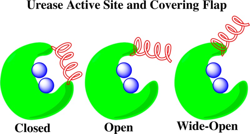
Helicobacter pylori have been implicated in an array of gastrointestinal disorders including, but not limited to, gastric and duodenal ulcers and adenocarcinoma. This bacterium utilizes an enzyme, urease, to produce copious amounts of ammonia through urea hydrolysis in order to survive the harsh acidic conditions of the stomach. Molecular dynamics (MD) studies on the H. pylori urease enzyme have been employed in order to study structural features of this enzyme that may shed light on the hydrolysis mechanism. A total of 400 ns of MD simulation time were collected and analyzed in this study. A wide-open flap state previously observed in MD simulations on Klebsiella aerogenes [Roberts et al. J. Am. Chem. Soc.2012, 134, 9934] urease has been identified in the H. pylori enzyme that has yet to be experimentally observed. Critical distances between residues on the flap, contact points in the closed state, and the separation between the active site Ni2+ ions and the critical histidine α322 residue were used to characterize flap motion. An additional flap in the active site was elaborated upon that we postulate may serve as an exit conduit for hydrolysis products. Finally we discuss the internal hollow cavity and present analysis of the distribution of sodium ions over the course of the simulation.
Introduction
Helicobacter pylori, formerly known as Campylobacter pylori, are Gram-negative spiral bacteria commonly found in the stomach lining of humans.1,2 Discovered in 1982, H. pylori was definitively linked in 1984 to gastritis following an experiment in which Barry Marshall ingested a Petri dish of the bacteria and within days developed gastritis symptoms.3−5 Since then H. pylori has been linked to gastric and duodenal ulcers, hepatic coma, non-ulcer dyspepsia and adenocarcinoma.6H. pylori bacteria thrive in the pH range 6–8, whereas the pH of the stomach is approximately 3. This environment is too acidic for the survival of H. pylori and in order to tolerate these harsh conditions, the bacteria produce large amounts of urease (10–15% total protein weight).
Urease [urea amidohydrolase EC 3.5.1.5] is an enzyme that hydrolyzes urea, initially forming ammonia and carbamate. The first enzyme to be isolated in crystalline form, urease was initially crystallized in 19267 and the molecular mass was first determined in 19348 in the seminal work of Sumner. Ureases are unique in that the active site incorporates Ni2+ ions; in fact, Jack Bean urease was the first Ni enzyme to be identified in 1975.9 Urea itself is quite stable in the pH range from 2 to 12 with a half-life of 3.6 years at a temperature of 38 °C.10 Urea owes its stability in part to the estimated 30–40 kcal/mol in stabilization energy it gains through resonance. Urease enhances the rate of urea hydrolysis roughly 1014-fold and the H. pylori enzyme is able to make use of the small 1.7 to 3.4 mM urease concentration available in the stomach due to its Michaelis constant (KM) of 0.17 mM.2,11H. pylori urease has a mass of 1.06 MDa and has 12 active sites containing two Ni2+ ions each.12 The enzyme has two subunits, of masses 62 and 29.5 kDa, labeled α and β, respectively. These subunits make up the dimeric αβ subunit (Figure 1) that is the repeat unit for the assembly of one of four trimers. Overall, the enzyme has a tetrahedral form (Figure 2) consisting of four triangle-shaped units where each triangle is a trimeric (αβ)3 unit giving the enzyme a total of 24 chains (12 α and 12 β).13
Figure 1.
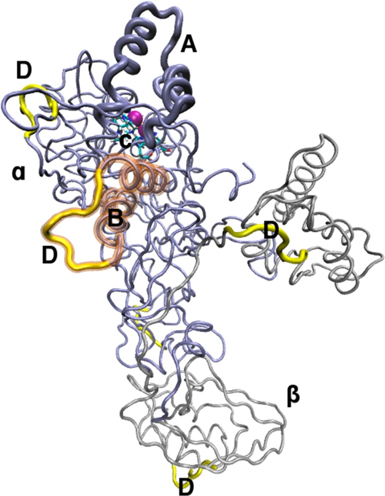
Single αβ dimeric subunit: chain β is colored silver (β); chain α is colored iceblue (α); the active site covering flap is given in bold iceblue (A); Ni2+ ions are shown as purple spheres; transparent brown highlights the α-helices of the second mobile flap (B), (see Results); active site residues in licorice (C); high RMSF regions are given in bold yellow (D).
Figure 2.
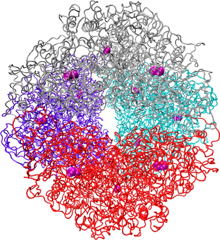
Entire structure of H. pylori urease. Each trimeric subunit of the tetramer is individually colored to depict the overall assembly. Ni2+ ions are depicted as purple spheres.
Many different varieties of urease are found in plants, fungi, and bacteria, including those enzymes found in H. pylori, Klebsiella aerogenes, Bacillus pasteurii, and Jack Bean (Canavalia ensiformis).10,14 The active site of H. pylori urease, like other ureases, is covered by a flap and has a barrel like shape. At the bottom of the barrel exists the Ni coordination site. This Ni2+ site contains both a penta- and hexacoordinate nickel, with coordinating ligands summarized in Table 1. In addition to the amino acid residues observed in the coordination sphere of the ions, a water molecule coordinates each Ni2+ ion and both are bridged by a hydroxide anion. These ligands have been implicated in the urea hydrolysis mechanism. The binding pocket is mostly lined with hydrophobic amino acids. Crystal structures of the ureases show that, in addition to the conserved residues in the active site, the ureases share conserved residues that make up the mobile flap that covers the active site.13,15,16 In H. pylori urease, the residues comprising the mobile flap are 313–346 on the α subunit.13 The residues that comprise the α-helix and turn portions of the mobile flap are identified in Table 1.
Table 1. Key Regions and Residues in HP Ureasea.
| region | residue numbers and typesb |
|---|---|
| pentacoordinate Ni2+ | LYSα219(CO2–), HISα248(δN), HISα274(εN), bridging –OH, H2O |
| hexacoordinate Ni2+ | LYSα219(CO2–), HISα136(εN), HISα138(εN), ASPα362(CO2–), bridging –OH, H2O |
| flap α-helix 1 | α313−α322 GLU-HID-MET-ASP-MET-LEU-MET-VAL-CYS-HIE |
| flap turn | α323−α329 HIP-LEU-ASP-LYS-SER-ILE-LYS |
| flap α-helix 2 | α330−α336 GLU-ASP-VAL-GLN-PHE-ALA-ASP |
Flap residues refer to areas as outlined in the crystal structure. Numbering is according to Ha et al.13
HID, HIE, and HIP refer to histidines with protonated δ, ε and both imidazole nitrogens, respectively.
Due to its implication in the survival of H. pylori in the stomach, despite the harsh acidic environment, inhibition of the urease enzyme is a logical point of attack for eradicating H. pylori infections and thus preventing the diseases these colonies cause. The development of novel treatments for this type of infection is imperative due to the emergence of antibiotic resistant strains. Indeed, the standard “triple therapy” of two antibiotics in conjunction with a proton pump inhibitor has been expanded to include bismuth compounds (quadruple therapy) to combat these resistant bacteria.17,18
Urease has received computational interest in recent years, via both Quantum Mechanical (QM) and Molecular Dynamics (MD) approaches. Musiani et al. used density functional and docking methods in a 2001 study to further investigate the mechanism of B. pasteurii urease hydrolysis and used steric and electrostatic criteria to distinguish the two most likely mechanistic pathways.19 Both MD and QM studies have been utilized in our laboratory in order to probe the pathway of urea decomposition in an attempt to further elucidate the mechanism of catalysis, with the MD study focusing on B. pasteurii urease.20−22 Carlsson and Nordlander used density functional theory to probe the nature of urea coordination to the nickel active site while studying the hydrolytic mechanism.23 Valdez and Alexandrova utilized their QM/DMD method in order to probe the natural selection of two Ni2+ ions in the urease enzyme active site, whereas nature selected two Zn2+ ions for β-lactamases, enzymes that share similar hydrolytic function.24 Barros et al. studied the Jaburetox-2Ec protein, derived from urease, which has potent insecticidal properties in another MD study.25 An older study by Manunza et al. probed only the active site of K. aerogenes urease in their investigation of urea and the urease inhibitors N-(N-butyl)-phosphoric triamide and acetohydroxamic acid binding to the dinickel site.26
Previous MD simulations on K. aerogenes urease, a much smaller enzyme than H. pylori urease, revealed a third flap state we refer to as the wide-open flap state which is notably distinct from the previously known open and closed flap states.27 Inspired by our simulations on the urease of K. aerogenes, we conducted MD simulations on H. pylori urease in order to ascertain whether a wide-open flap state is observed in this enzyme as well. Furthermore, we analyzed other regions of the enzyme and finally investigated the behavior of the sodium. Herein, we present the results of the first MD simulation on H. pylori urease, which spans a 400 ns duration on this large protein (148 648 atoms in the protein and 307 839 in total). Importantly, this simulation provides us with up to 4.8 μs (400 ns *12 flaps) of flap motion information if the motions are not correlated (weak, if any, correlation has been noticed between the flaps based on this simulation).
Methods
Structure Preparation
We used the PDB structure 1E9Z as the starting point.13 The PDB contains 1/12 of the total structure; therefore, PyMOL(28) was used in order to reflect the structure 11 times, thereby generating the entire dodecameric HP urease structure. The online protonation server H++ was used to obtain the correct protonation states of the amino acids throughout the structure at a pH of 7.5.29−32 The dodecamer was split into 12 PDB files with each renumbered from one, keeping the canonical numbering from the PDB. Each PDB was protonated in the absence of Ni2+ ions and the carboxylate of the carbamylated lysine residue (LYS/KCB457). Following pronation using standard pKa values, the carboxylate was added, the Ni2+ ions were reintroduced and the protonation states of histidine residues bound to the Ni2+ were corrected. Finally, the 12 individual PDBs files were renumbered and concatenated into a PDB file representing the entire dodecamer. We took extra care with the nickel coordination site, which is located at the bottom of each of the 12 active sites. A bonded model was created with the aid of the tLeap facility of AmberTools version 1.533 where bonds involving Ni2+ ions were defined; subsequently, hydrogen atoms and water molecules were added to the entire structure. The prepared model was neutralized with the addition of 44 Na+ ions placed by tLeap and solvated with a periodically replicated octahedral water box using tLeap using the TIP3P triangulated water model. A total of 53,048 water molecules were used to hydrate the structure. The metal parameters developed by Roberts et al. with the MTK++/MCPB utility of AmberTools for K. aerogenes urease27 were modified by utilizing previously developed Lennard-Jones parameters34 (R* and ε) for Zn2+ as parameters for the Ni2+ radii.
Minimization and Equilibration
The energy minimization of the structure was performed using a two-stage procedure: we first minimized the nickel coordination sites by imposing weak harmonic positional restraints of 10 kcal/(mol·Å2) on all atoms outside the Ni coordination sphere. The steepest descent method was first used for 1 × 10⁵ steps to minimize the active site. Subsequently, the entire structure was relaxed and minimized using steepest decent for 1 × 10⁴ steps. The initial step length was decreased to 1 × 10⁻⁶ Å. After minimization, we equilibrated the structure employing a two-stage process. In the first stage, the temperature was raised from 0 to 300 K over 1 × 10⁶ steps of MD with a step size of 0.002 ps (2 fs) in the canonical (NVT) ensemble. This applied a weak harmonic positional restraint on the whole protein. After the system was brought to 300 K, the simulation was run for 10 ps in the isobaric, isothermal (NPT) ensemble after removal of all the harmonic restraints. The temperature control was performed using Langevin dynamics with a collision frequency γ of 2.0 ps–1 in the first and 1.0 ps–1 in the second equilibration stage. SHAKE35 was used to constrain all hydrogen-containing bonds during both equilibration steps.
MD Simulation
The production MD run was procured over 400 ns in the isobaric, isothermal (NPT) ensemble, which was acquired using 2.0 × 10⁸ steps, with a 0.002 ps time step using the PMEMD version of AMBER12(36,37) on an M2090 GPU using the FF99SB force field. The temperature was kept constant at 300 K using Langevin dynamics with a collision frequency of 1.0 ps–1 while the pressure was maintained at 1 bar with a pressure relaxation time of 2.0 ps. SHAKE was again used to constrain all hydrogen-containing bonds. For the calculation of the nonbonded interactions, we made use of the particle mesh Ewald method and a cutoff distance of 8 Å was employed while computing the long-range electrostatic interactions. Frames were saved every 5 × 10³ steps (10 ps), providing 4 × 10⁴ frames.
Analysis and Residue Numbering
The frames were analyzed for flap state-defining residue separations, RMSD, atomic fluctuations (RMSF) and correlation matrices using the ptraj utility of AmberTools version 1.5. RMSD (root mean squared deviation) was obtained for each atom in the entire protein with the first frame of the trajectory as the reference and gives an average deviation of the protein geometry from the reference structure at each point over the simulation time. We also separated out the residues involved in the motion of the active site-covering flaps and obtained the RMSD for each of these. The RMSF (root mean squared fluctuation) was computed on a per residue basis, using the α carbon of each residue as the reference point and providing a time-averaged value.
Throughout our discussion of the enzyme, we will identify both the residue numbering according to Ha et al. (α and β chains), as well as the residue numbering from the PDB (1–807). For the purposes of this analysis the flap covering the active site was considered to span residues α304–347 (542–585) with the first α-helix composed of residues α304–322 (542–560), the turn composed of α323–329 (561–567) and the second α-helix spans α330–347 (568–585). The α-helices are extended from the helical section described by Ha et al.13 in order to account for all residues in the flap region that adopt α-helical character at some point during the simulation.
Results and Discussion
RMSD
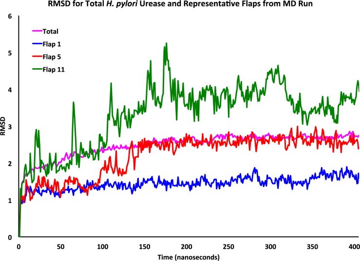
The root-mean-square deviation (RMSD, Figure 3) was obtained for the entire structure and of each flap individually using the first frame after equilibration as the reference point. The RMSD of the entire structure levels off approximately 250 ns into the simulation at a value of approximately 2.5 Å. For the flap that remains closed (flap 1), the maximum RMSD found over time was 1.87 Å and overall this flap undergoes only modest fluctuation. For the semiopen flap state displayed in Figure 3 (flap 5), the maximum observed RMSD is approximately 3 Å; Flap 5 was observed to have an RMSD that did not vary appreciably from 2.6 Å after 150 ns. In the wide-open flap (flap 11) the RMSD reaches 5.25 Å and after two-thirds of the simulation remains around 3.8 Å before dipping slightly over the final 50 ns, although at a value well above the total simulation RMSD. Further RMSD plots for the remaining flaps are provided in the Supporting Information (SI) (Figures S5–S7).
Figure 3.
RMSD (Ångstroms) of the entire H. pylori urease structure (purple), and the closed (blue), semiopen (red), and wide-open (green) flap states.
RMSF
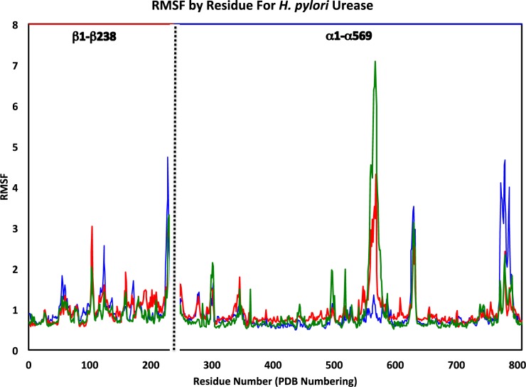
The RMS fluctuation (RMSF) of each dimer was obtained and representative results are shown in Figure 4 for the three flap states (remaining RMSF plots are provided in the SI, Figures S8–S10). RMSF was determined based on the α-carbon of each residue. We define “average RMSF plus one standard deviation” as the threshold for a residue considered as “high RMSF.” Recall that HP urease consists of 12 identical αβ dimers, for a total of 24 chains. Each dimer contains one binding pocket with two Ni2+ ions and one flap, which will be referred to as flaps 1–12 to differentiate between them. After plotting the RMSF of each dimer it was apparent that there were repeating regions of high flexibility.
Figure 4.
RMSF for αβ dimers representing the wide-open (green), semiopen (red), and closed (blue) flap states with sequential numbering from the PDB (1–807). Residues 1–238 correspond to the β-chain and residues 239–807 form the α-chain.
It was expected that the residues of the flap region covering the active site, α304–347 (542–585) would have high RMSF values and this was indeed true for all 12 dimers, with the exception of the first, where the flap was observed to remain essentially closed. The other regions that have high RMSF values, almost in every dimer, were residues β100–106 (100–106), β226–232 (226–232), α60–65 (298–303), α388–395 (626–633), and α538–545 (776–783) (Table 2). The β100–106 (100–106) region lies within a bridge in a small group of amino acids that link two approximately 100 amino acid regions. Near the end of the β-chain are residues β226–232 (226–232) that make up one of the 8 vertices of the dodecameric structure. These amino acids are part of a C-terminus extension of the beta chain as compared to the ureases of K. aerogenes and B. pasteurii.13 Residues α60–65 (298–303) are located on the interior of the dodecamer near a vertex where ion density is observed in the MD simulation (vide infra). Finally, the residues α538–545 (776–783) comprise the loop portion of an ancillary flap close in proximity to the flap covering the active site. Of note is the observation that in the dimer where the flap remains closed, these residues have the highest observed RMSF of any of the remaining 11 dimers. In fact, in this dimer each residue from α533–553 (771–791) is observed to have significantly higher RMSF values. Based on an analysis of the trajectory, this final high RMSF region is most mobile when the active site covering flap is closed and exhibits the least amount of motion when the flap is in the wide-open state.
Table 2. High RMSF Regions and Residues with α/β Numbering According to Ha et al. and the Corresponding Sequential Numbering from the PDB (1–807).
| residue range | amino acids |
|---|---|
| β100−β106 (100–106) | ILE-GLU-ALA-ASN-GLY-LYS-LEU |
| β226−β232 (226–232) | ALA-LYS-SER-ASP-ASP-ASN-TYR |
| α60−α65 (298–305) | ASN-PRO-SER-LYS-GLU-GLU |
| α388−α395 (626–633) | GLY-ARG-LEU-LYS-GLU-GLU-LYS-GLY |
| α538−α545 (776–783) | VAL-ASN-PRO-GLU-THR-TYR-HIS-VAL |
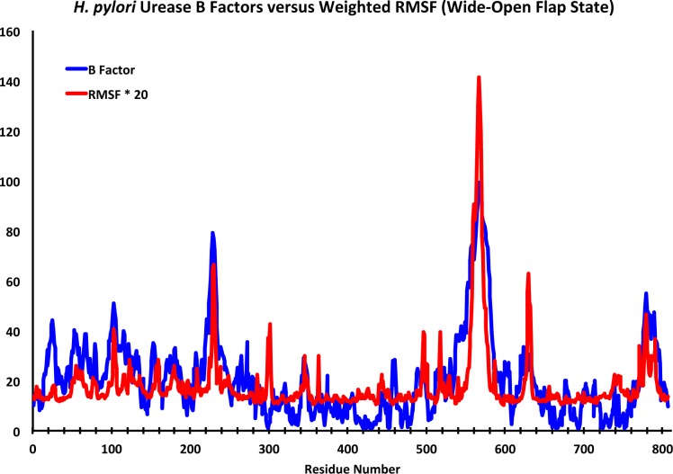
Figure 5 depicts the B factors from the X-ray structure of Ha et al.13 plotted against scaled RMSF values for the dimer that adopts the wide-open active site flap conformation. The RMSF profile matches up quite well with the experimental B factors, which supports the reliability of our molecular dynamics simulation. One of the particularly interesting high RMSF regions spanned residues α388−α395 (626–633) and this group of amino acids constitutes the loop portion of what has been identified as a second mobile flap in the active site region (Figure 6). This flap has a profile similar to the experimental data for inhibitor complexes of B. pasteurii and S. pasteurii reported by Benini and co-workers.16 This flap consists of two α-helices spanning residues α372−α387 (610–625) and α398−α410 (636–648) and the loop portion, just as the flap that covers the active site. One of the key differences observed in the two flaps during the MD simulation was that while both α-helices were observed to lose α-helical character in the active site covering flap, the helices are quite rigid in this second flap. This loop is observed to be highly flexible in each of the 12 αβ dimers over the course of the simulation. This flap is positioned near one of the vertices that allow direct access of molecules into the hollow, suggesting it may affect entrance into and egress from the internal cavity. While a number of hypotheses are possible we speculate that this flap may serve as an entrance/exhaust conduit that allows for the exit of hydrolysis products from the active site. Analysis of the MD trajectory reveals one sodium ion clearly passing through the first flap (residues 771–791; α533−α553) and other ions briefly interacting. Due to the large accumulation of sodium ions in the hollow, the low occurrence of Na+ ion interaction with this flap may be a concentration issue and studies underway with higher ion concentration (Na+ and NH4+) would be better able to support or reject the proposed conduit hypothesis.
Figure 5.
H. pylori urease X-ray B factors13 versus scaled RMSF for the (αβ) dimer reaching wide-open flap state (flap 11). The RMSF has been multiplied by a factor of 20 for easy visual comparison with the urease B factors.
Figure 6.
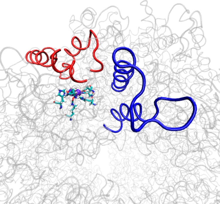
Positions of the second active site flap (blue), the flap covering the active site (red) and the active site.
Analysis of the RMSF values of the flaps covering the active site (defined as residues α304−α347 (542–585) for our analysis) reveals that in 11 of the 12 flaps, one per αβ dimer, residues α324−α328 (562–566) have the highest RMSF values as expected based on the known flexibility of this region. Comparison of the two α-helices (residues α304−α322 (542–560) make up the first helix and residues α330−α347 (568–585) form the second as determined from the MD simulation) reveals that the residues comprising the second α helix have much higher RMSF values than those of the first. Additionally, we observe that the loop region residues have the highest RMSF values, particularly residues α326−α329 (564–567). In 11 of the 12 αβ dimers, these loop residues have RMSF values greater than any other residues of the α304−α347 (542–585) domain. As expected, the highest RMSF values in the loop region are observed in the flap (flap 11) that reaches the wide-open state. No flap residues were found to have high RMSF values in the αβ dimer that remained in the closed flap state throughout the MD simulation.
Active Site Access Flap Motion Analysis
Having been previously implicated in allowing urea access to the active site, we focus our attention in the next several sections on an enhanced analysis of the behavior of the active site covering flap over the course of the MD simulation. Distances between points on the flap and opposite points at the access point are used to probe the extent of flap opening, and the distances between the critical HISα322 residue and the catalytically active Ni2+ centers of the active site are studied. This analysis reveals a wide-open flap state that develops over the course of the simulation. While this wide-open state has not been experimentally observed, the high disorder observed in these flaps in many ureases indicates it should be an accessible state, as is the case in K. aerogenes urease.15 Finally, relative free energy maps constructed using these distances are used to elucidate the flap states that can be readily identified in the H. pylori urease structure over the duration of the MD simulation.
Critical Distances
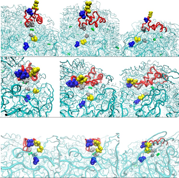
The flap motion was assessed by measuring the distances between three points on the flap and three facing points at the distal end of the flap on the protein. The first distance compares the separation between ILEα328 and ALAβ170. The ILEα328 residue resides at the tip of the flap and the ALAβ170 residue is the nearest nonbonding neighboring residue when the flap is closed. The remaining two distances involve the tips of the α-helices and the corresponding nearest neighbors upon flap closure. These distances are between HISα322 and GLYα47, and GLUα330 and ALAβ173, where the HIS and GLU residues are those that reside at the α-helix tips, and are illustrated in Figures 7a–i.
Figure 7.
Representative conformations illustrating residue separation in the closed (bottom), semiopen (middle), and wide-open states (top). The first column perspective is head-on, the second angled and the third perpendicular with respect to the flap. Blue residues depict the ILEα328/ALAβ170 separation, yellow shows HISα322/GLYα47, and silver shows GLUα330/ALAβ173.
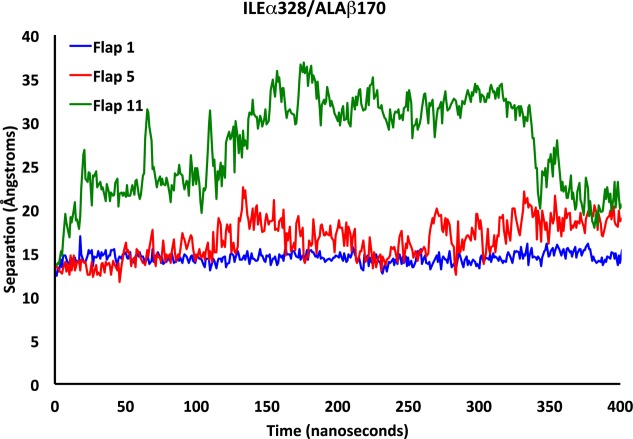
We characterized the states associated with flap motion by recording and analyzing measurements of these three distances for each of the 12 flaps. Figure 8 displays representative ILEα328/ALAβ170 separations for the closed, semiopen, and wide open flap states. In the closed state, the separation of these residues varies only slightly, oscillating within the 13.5–16 Å range, with slightly more variation observed in the semiopen state where the separation is observed to fluctuate between 12 and 22 Å. In the wide-open state, the distance between these residues increases dramatically to over 38 Å. The separation remains high until the last 50 ns, where it rapidly declines to about 20 Å. This is in accord with the visual inspection of the protein. Flap 11 is the only flap that adopts a clear wide-open state conformation. It is already known in the literature that there is an open state for the flaps that involves the loop region and a partial uncoiling of one of the α-helices.13 Further discussion of residue separations used to characterize flap motion and the width of opening are presented in pages S2–S8 of the Supporting Information.
Figure 8.
Separation between residues ILEα328 and ALAβ170 over time for flaps representing the closed (blue), semiopen (red), and wide-open (green) flap states.
Free Energy Maps
In order to further elucidate the various flap states, relative free energy maps were constructed based on the methodology described in Toba et al.38 These maps were produced by first ascertaining the probability of any two of the residue separations described above coexisting in any given frame of the 40 000 collected during the simulation. These probabilities were then utilized to determine the relative free energies of the states via eq 1, where R is the ideal gas constant, T the temperature and Pi the probability of any two distinct residue distances coinciding in a randomly selected MD frame. The data was processed using an in-house script.
| 1 |
The first three relative free energy maps were produced based on the separations between the residue pairs ILEα328/ALAβ170, HISα322/GLYα47, and GLUα330/ALAβ173. The variation observed in the separations between the ILEα328/ALAβ170 residues represents the largest range of distances among the three residue pairs analyzed, ranging from 10 to 37 Å. The GLUα330/ALAβ173 separation ranges from approximately 6 to 31 Å and the HISα322/GLYα47 distances were found to take values from 5 to 20 Å. From a general observation of the three free energy maps produced, it seems that the loop regions move more freely followed by the α-helix ending in the glutamate then the α helix ending with HISα322. If we analyze the free energy maps produced using the distances described above, we observe a wide-open flap state in each plot. In Figure 9, we have the HISα322 to GLYα47 distance versus the ILEα328 to ALAβ170 distance. In the residue separation ranges ∼34 Å between ILEα328 and ALAβ170 and ∼19 Å between HISα322 and GLYα47, we observe local minima that lie 2 to 2.4 kcal/mol above the minimum. The closed state occurs at distances of 13 to 15 Å on ILEα328/ALAβ170 and 7 to 8 Å on HISα322/GLYα47. We also observe many interim states, with one intermediate state that is very evident located at distances of 25 to 30 Å separating ILEα328/ALAβ170 and a HISα322/GLYα47 separation of roughly 9 to 10 Å.
Figure 9.
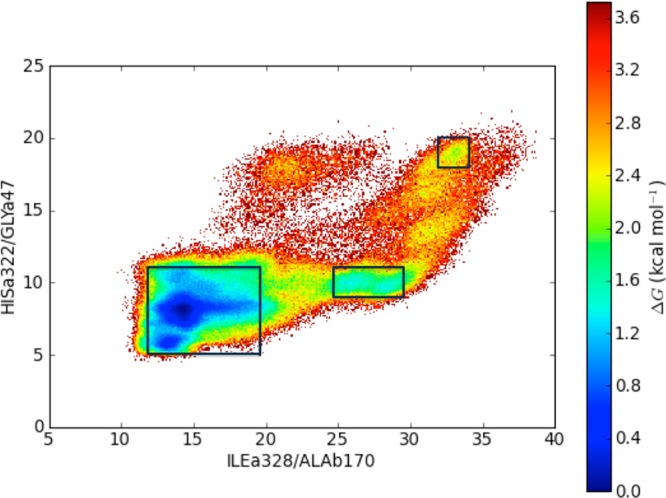
Relative free energy diagram constructed based on the separation between ILEα328/ALAβ170 and HISα322/GLYα47. Regions identified as local minima representing the closed, semiopen and wide-open states are boxed.
The second free energy map (Figure S28, see SI) was derived from the GLUα330/ALAβ173 and HISα322/GLYα47 separations. The HISα322/GLYα47 separations span a range that is much smaller than those of GLUα330/ALAβ173. We can observe the wide-open flap state at separations of 19 Å between HIS and GLY and 26–27 Å between GLUα330 and ALAβ173. The energy well associated with the wide-open flap state resides approximately 2.4 to 2.8 kcal/mol above the minimum. The minimum observed in this plot resides at distance ranges 6 Å for GLUα330/ALAβ173 and 5.5–8 Å for HISα322/GLYα47. In this plot, we observe large ranges of stable energies while keeping the HISα322/GLYα47 distance constant and the GLUα330/ALAβ173 distance varies implying more mobility possessed by the GLUα330 residue and the α helix on which it is located.
Figure S29 (see SI) displays the relative free energy map constructed based the GLUα330/ALAβ173 and ILEα328/ALAβ170 residue separations. Here, we are able to identify four distinct regions representing local minima. One at which both the GLUα330/ALAβ173 (27–32 Å) and ILEα328/ALAβ170 (∼30–35 Å) distances are large, another at which both the GLUα330/ALAβ173 (13–15 Å) and ILEα328/ALAβ170 (∼6 Å) distances are small, and 2 other regions: one at which the GLUα330/ALAβ173 distance is large (14–16 Å) and the ILEα328/ALAβ170 distance (11–15 Å) is small, and a second where the ILEα328/ALAβ170 distance is large (∼25–27 Å) and the GLUα330/ALAβ173 distance is intermediate (∼17–21 Å).
A final free energy map (Figure S30, see SI) was developed based on the separation between the HISα322-εN and both nickel ions. In this free energy map, we are able to observe three distinct states, all energetically accessible, that define the closed, semiopen, and wide-open flap states. The different states occur at approximately 6–11, 15–18, and 21–24 Å separations. This map clearly illustrates the presence of the three flap states.
Additional Structural Features
There exist additional features of the H. pylori urease structure that are of interest aside from the aforementioned active site flap. Some of the discussed features below are reaffirmations of, and further elaboration on, the behavior of structural aspects of the enzyme that have been previously described in the crystallographic studies, such as the presence of the interior hollow. Finally, we comment on the distribution of sodium ions during the course of the simulation as ion channeling has been hypothesized to be critical in both the hydrolysis process as well as in the accumulation of ammonia/ammonium in the hollow.
Radius of Gyration
We obtained the radius of gyration for the urease enzyme, as well as the maximum radius (see SI, Figure S31). The radius of gyration is the average distance of all atoms from the center of the protein. For H. pylori urease the radius of gyration ranged from 60 to 61.8 Å over the course of our simulation. At the 230 ns mark the radius leveled off and oscillated between 61.6 and 61.8 Å. The maximum radius ranged from 86 to 96 Å and can be partly attributed to the motion of the flaps located on the protein surface.
The Hollow
H. pylori urease has an internal hollow with an estimated volume of ∼145−156 Å3, and it has been hypothesized that this hollow acts as a reservoir of ammonia/ammonium ions.13 Over the course of the simulation, limited motion is observed in the hollow-defining residues, indicative of a relatively constant volume in the internal cavity. We chose to track the behavior of sodium ions in order to ascertain whether this cation accumulates in the hollow as well. In characterizing the residues outlining the hollow, we observed that the first residues that we encounter as we move in from the center of the hollow were glutamates and, more specifically, the α505 glutamates. Eleven of these residues do not have high RMSF values based on our “average + one standard deviation” selection criterion, implying a somewhat rigid placement within the hollow. Further analysis was performed by taking the average structure of the enzyme over the entire 40 000 frames produced by the simulation, setting the origin as the protein center of mass, and generating an average PDB structure. While the net charge of all residues within 60 Å of the protein center of mass is −16 (36.4% of total protein charge), the innermost residues of the protein (within 22 Å of the center of mass) are the 12 glutamate α505 residues that place a net −12 charge nearest the hollow center and extension of the radius from the center of mass to 23 Å introduces the first positively charged residue, a single lysine, as well as three additional glutamates for a net charge of −14. This should permit the hollow to accommodate and stabilize a large positive charge. If this is indeed the case, the sodium ion distribution over the course of the MD run should reflect this fact.
The radial distribution function of the Na+ ions from a dummy atom placed at the origin was calculated over a 95 Å radius with 0.5 Å bins using the average PDB structure. Among the more interesting observations is the fact that of the 44 sodium ions in the system, on average over the entire 400 ns, 30 were found in the hollow within 20.25 Å of the dummy atom located at the protein center of mass as illustrated by the integrated radial distribution function in SI Figure S32. We observe eight distinct peaks within the first 20.25 Å in the radial distribution function at 0.75, 2.25, 6.75, 8.75, 11.25, 15.25, 16.75, and 18.25 Å and there are eight minima within the same span at 1.75, 5.25, 8.25, 10.75, 14.75, 16.25, 17.75, and 20.25 Å and the values of the respective maxima and minima decay over this span until reaching zero at 20.25 Å (SI, Figures S32–S33). Figure 10 depicts one hemisphere of the first shell of atoms encountered from the dummy atom placed at the center of mass, with the glutamate residues highlighted to illustrate their position as the innermost residues of the hollow. Figure 11 illustrates the maxima in the Na+ ion radial distribution function as shells extending from the center of mass and terminating at each respective maximum. The highlighted sodium ions (blue spheres) clearly illustrate the regions of highest probability of locating a sodium ion within the hollow, and these regions are shown out to 20 Å from the center of mass. This depiction further supports the conclusion that the hollow is an apt reservoir for positively charged ions.
Figure 10.
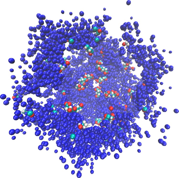
First shell of atoms for one hemisphere of HP urease. Glutamate residues are depicted as van der Waals spheres.
Figure 11.
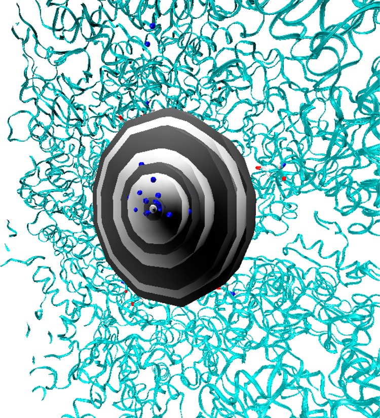
Cross-section illustrating the respective maxima in the Na+ ion radial distribution function up to 20 Å from the protein center of mass using concentric gray and black spheres that terminate at each maximum in the function. Na+ ions are depicted as blue van der Waals spheres and the residues shown in licorice are residues within 22 Å of the center of mass (all glutamate residues).
Sodium Ion Distribution
The trajectory was further analyzed to determine the sodium ion distribution in our H. pylori urease MD simulation. We did this by placing, over each frame of the simulation, a grid with 1 Å3 cells and counted the number of times a sodium ion appeared in any given cell. This generated a histogram that provides a representation of the sodium ion distribution over the 40 000 simulation frames. It was shown that most of the sodium ions were found in three major parts of the protein (Figure 12). The first major concentration is observed at the ovoid holes of the 2-fold symmetry axes. These ovoid holes have a shorter diameter that fluctuates between 12 and 14 Å over the course of the simulation, with the larger diameter varying from 22 to 25 Å. These distances vary slightly from the crystal structure, where the “short” and “large” diameters were observed to be ∼11.5 and 24.5 Å, respectively.13 Both Na+ ions and H2O molecules were observed entering and exiting these portals. The second major location where sodium ions were found is by the active site flaps. Flap 1, the closed flap, had the highest concentration of sodium ions out of the 12 flaps. The third major region with a high distribution of sodium ions is the internal hollow, and as observed in the radial distribution function, this region had the highest probability of a sodium ion being present. This is consistent with observations made while examining the hollow, as Na+ ions were observed throughout the simulation in this cavity.
Figure 12.
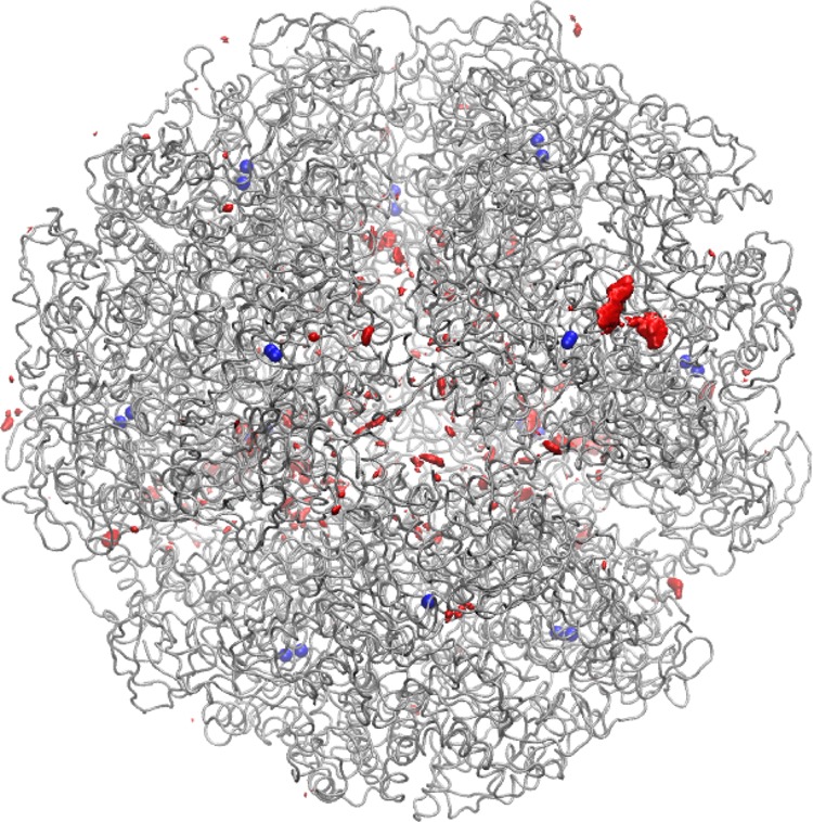
Na+ ion distribution (red) with Ni2+ ions (blue) pinpointing the location of each active site.
Conclusions
We have reported the first MD simulation on the H. pylori urease enzyme, totaling 400 ns. Among our observations are the presence of a third flap state, referred to as the wide-open flap state, that has also been observed in a simulation of K. aerogenes urease.27 Although it has not been directly observed experimentally there are hints that, indeed, the flap region is far more dynamic than generally believed. For example, in a reported X-ray structure of K. aerogenese urease the flap region was not resolved by disorder suggesting a rich conformational ensemble.15 We have also further elaborated upon a flap located in the posterior of the active site cavity. The simulation reveals that Na+ ions are capable of channeling through this flap into the hollow, specifically when the active site cover flap is in the closed state. The 12 glutamate α505 residues are, on average, the first residues encountered from the protein center of mass and are the only residues encountered extending out 22 Å from the center of mass of the average PDB structure, providing a net −12 charge (−14 when the radius is extended to 23 Å). This accumulation of negative charge (31.8% of total H. pylori urease charge at a radius of 23 Å from the average PDB center of mass) helps explain the larger distribution of sodium ions observed in the interior. We observed that there were distinct regions of the protein in which the protein was very mobile, although the volume of the internal cavity remained comparatively unchanged. Furthermore, there were distinct regions with high of Na+ ion occupancies during the MD simulation including the internal hollow, which clearly exhibited the highest concentration of sodium ions over the course of the simulation. Two other regions exhibited high Na+ distributions: the ovoid holes centered about the 2-fold symmetry axes and the flap that remained in the closed state.
These findings further our understanding of the structure and function of the ureases, as well as assist in the rationalization and design of inhibitors of H. pylori urease. The wide-open flap conformation in particular opens the door for development of a host of new, larger inhibitor molecules hitherto considered inaccessible to the active site cavity. These larger compounds could enter the active site cavity blocking urea from entering the catalytic region. We are currently exploring these possibilities.
Acknowledgments
This research was funded by National Institutes of Health (NIH) grant R01 GM066859. M.S.M. thanks the National Science Foundation (NSF) for support in the form of a graduate research fellowship, the UF Disability Resource Center, Juan Contreras and Sean Jones. We thank the UF HPC center for generous allocations of GPU time. We thank Dr. Dhruva Chakravorty and Dr. Billy Miller for many useful discussions during this project.
Supporting Information Available
Extended characterization of the active site-covering flap, additional plots containing information on RMSD, RMSF, residue separations, free energy maps, radius of gyration, and sodium ion distribution. This material is available free of charge via the Internet at http://pubs.acs.org.
The authors declare no competing financial interest.
Funding Statement
National Institutes of Health, United States
Supplementary Material
References
- Ferrero R. L.; Hazell S. L.; Lee A. J. Med. Microbiol. 1988, 27, 33. [DOI] [PubMed] [Google Scholar]
- Hu L. T.; Mobley H. L. T. Infect. Immun. 1990, 58, 992. [DOI] [PMC free article] [PubMed] [Google Scholar]
- Marshall B. Lancet 1983, 1, 1273. [PubMed] [Google Scholar]
- Marshall B. J. Med. J. Australia 1985, 143, 319. [PubMed] [Google Scholar]
- Marshall B. J.; Warren J. R. Lancet 1984, 1, 1311. [DOI] [PubMed] [Google Scholar]
- Buck G. E. Clin. Microbiol. Rev. 1990, 3, 1. [DOI] [PMC free article] [PubMed] [Google Scholar]
- Sumner J. B. J. Biol. Chem. 1926, 69, 435. [Google Scholar]
- Sumner J. B.; Gralen N.; Quensel I. B. E. Science 1938, 87, 395. [DOI] [PubMed] [Google Scholar]
- Zerner B. Bioorg. Chem. 1991, 19, 116. [Google Scholar]
- Karplus P. A.; Pearson M. A.; Hausinger R. P. Acc. Chem. Res. 1997, 30, 330. [Google Scholar]
- Mobley H. L. T.; Island M. D.; Hausinger R. P. Microbiol. Rev. 1995, 59, 451. [DOI] [PMC free article] [PubMed] [Google Scholar]
- Pinkse M. W. H.; Maier C. S.; Kim J. I.; Oh B. H.; Heck A. J. R. J. Mass. Spectrom. 2003, 38, 315. [DOI] [PubMed] [Google Scholar]
- Ha N. C.; Oh S. T.; Sung J. Y.; Cha K. A.; Lee M. H.; Oh B. H. Nat. Struct. Biol. 2001, 8, 505. [DOI] [PubMed] [Google Scholar]
- Follmer C. J. Clin. Pathol. 2010, 63, 424. [DOI] [PubMed] [Google Scholar]
- Jabri E.; Carr M. B.; Hausinger R. P.; Karplus P. A. Science 1995, 268, 998. [PubMed] [Google Scholar]
- Benini S.; Rypniewski W. R.; Wilson K. S.; Miletti S.; Ciurli S.; Mangani S. Struct. Fold. Des. 1999, 7, 205. [DOI] [PubMed] [Google Scholar]
- Chey W. D.; Wong B. C. Y. Am. J. Gastroenterol. 2007, 102, 1808. [DOI] [PubMed] [Google Scholar]
- Malfertheiner P.; Bazzoli F.; Delchier J. C.; Celinski K.; Giguere M.; Riviere M.; Megraud F.; Grp P. S. Lancet 2011, 377, 905. [DOI] [PubMed] [Google Scholar]
- Musiani F.; Arnofi E.; Casadio R.; Ciurli S. J. Biol. Inorg. Chem. 2001, 6, 300. [DOI] [PubMed] [Google Scholar]
- Estiu G.; Merz K. M. J. Am. Chem. Soc. 2004, 126, 11832. [DOI] [PubMed] [Google Scholar]
- Estiu G.; Merz K. M. Biochemistry—U.S. 2006, 45, 4429. [DOI] [PMC free article] [PubMed] [Google Scholar]
- Estiu G.; Suarez D.; Merz K. M. J. Comput. Chem. 2006, 27, 1240. [DOI] [PubMed] [Google Scholar]
- Carlsson H.; Nordlander E. Bioinorg. Chem. Appl. 2010, 364891. [DOI] [PMC free article] [PubMed] [Google Scholar]
- Valdez C. E.; Alexandrova A. N. J. Phys. Chem. B 2012, 116, 10649. [DOI] [PubMed] [Google Scholar]
- Barros P. R.; Stassen H.; Freitas M. S.; Carlini C. R.; Nascimento M. A. C.; Follmer C. BBA—Proteins Proteom. 2009, 1794, 1848. [DOI] [PubMed] [Google Scholar]
- Manunza B.; Deiana S.; Pintore M.; Gessa C. Soil. Biol. Biochem. 1999, 31, 789. [Google Scholar]
- Roberts B. P.; Miller B. R.; Roitberg A. E.; Merz K. M. J. Am. Chem. Soc. 2012, 134, 9934. [DOI] [PMC free article] [PubMed] [Google Scholar]
- The PyMOL Molecular Graphics System; V. r., Schrodinger, LLC: Cambridge, MA, 2010. [Google Scholar]
- H++ Protonation Server. http://biophysics.cs.vt.edu/H++ (accessed March 28, 2012).
- Anandakrishnan R.; Aguilar B.; Onufriev A. V. Nucleic Acids Res. 2012, 40, W537. [DOI] [PMC free article] [PubMed] [Google Scholar]
- Myers J.; Grothaus G.; Narayanan S.; Onufriev A. Proteins 2006, 63, 928. [DOI] [PubMed] [Google Scholar]
- Gordon J. C.; Myers J. B.; Folta T.; Shoja V.; Heath L. S.; Onufriev A. Nucleic Acids Res. 2005, 33, W368. [DOI] [PMC free article] [PubMed] [Google Scholar]
- Case D. A.; Darden T. A.; Cheatham T. E. I.; Simmerling C. L.; Wang J.; Duke R. E.; Luo R.; Walker R. C.; Zhang W.; Merz K. M.; Roberts B.; Wang B.; Hayik S.; Roitberg A.; Seabra G.; Kolossvai I.; Wong K. F.; Paisani F.; Vanicek J.; Liu J.; Wu X.; Brozell S. R.; Steinbrecher T.; Gohlke H.; Cai Q.; Ye X.; Wang J.; Hseih M.-J.; Cui G.; Roe D. R.; Mathews D. H.; Seetin M. G.; Sagui C.; Babin V.; Luchko T.; Gusarov S.; Kovalenko A.; Kollman P. A.. AMBER 11; University of California: San Francisco, 2010. [Google Scholar]
- Merz K. M. J. Am. Chem. Soc. 1991, 113, 406. [Google Scholar]
- Ryckaert J. P.; Ciccotti G.; Berendsen H. J. C. J. Comput. Phys. 1977, 23, 327. [Google Scholar]
- Case D. A.; Darden T. A.; Cheatham T. E. I.; Simmerling C. L.; Wang J.; Duke R. E.; Luo R.; Walker R. C.; Zhang W.; Merz K. M.; Roberts B.; Hayik S.; Roitberg A.; Seabra G.; Swails J.; Goetz A. W.; Kolossvai I.; Wong K. F.; Paisani F.; Vanicek J.; Wolf R. M.; Liu J.; Wu X.; Brozell S. R.; Steinbrecher T.; Gohlke H.; Cai Q.; Ye X.; Wang J.; Hseih M.-J.; Cui G.; Roe D. R.; Mathews D. H.; Seetin M. G.; Salomon-Ferrer R.; Sagui C.; Babin V.; Luchko T.; Gusarov S.; Kovalenko A.; Kollman P. A.. AMBER 12; University of California: San Francisco, 2012. [Google Scholar]
- Goetz A. W.; Williamson M. J.; Xu D.; Poole D.; Le Grand S.; Walker R. C. J. Chem. Theory Comput. 2012, 8, 1542. [DOI] [PMC free article] [PubMed] [Google Scholar]
- Toba S.; Colombo G.; Merz K. M. J. Am. Chem. Soc. 1999, 121, 2290. [Google Scholar]
Associated Data
This section collects any data citations, data availability statements, or supplementary materials included in this article.


