Abstract
A snake crawling on horizontal surfaces between two parallel walls exhibits a unique wave-like shape, which is different from the normal shape of a snake crawling without constraints. We propose that this intriguing system is analogous to a buckled beam under two lateral constraints. A new theoretical model of beam buckling, which is verified by numerical simulation, is firstly developed to account for the special boundary conditions. Under this theoretical model, the effect of geometrical parameters on the deformation shape, such as the distance between walls, length of the snake and radius of the snake, is examined. The buckling beam model is then applied to explain qualitatively the wave-like shape of the snake.
Keywords: buckling, beam, snake locomotion, morphology
1. Introduction
An elastic beam under axial compression becomes unstable when the compressive stress exceeds the critical threshold for buckling. While buckling beams without lateral constraints have been analysed systematically [1], Adan et al. [2] have shown numerically and experimentally that buckling beams under a lateral constraint exhibit bifurcation modes that are distinct from that without lateral constraints. Under two parallel lateral constraints, Chai [3,4] has shown that the buckling of a simple supported beam exhibits new categories of buckling modes, as well as different transition behaviours between these modes, compared with the one-side constraint.
While beam buckling under lateral constraint appears to be a pure mechanics problem, it could also provide interesting insights for morphogenesis in natural and engineered systems [5]. Recently, Marvi & Hu [6] showed that when a snake crawls between two parallel walls, its body takes a unique rectangular wave-like shape which also depends on the wall spacing. In general, a snake usually moves forward in four ways: slithering by lateral undulation of the body, rectilinear progression by unilateral contraction/extension of their belly, concertina-like motion by folding the body similar to the pleats of an accordion and sidewinding motion by throwing the body into a series of helices [7,8]. Lateral undulation is the most common way for snakes to move forward, in which the sinusoidal-like lateral bending of body is propagated from head to tail. If a snake is forced to crawl through crevices between rocks, then its body may be required to conform to the shape of the narrow curvy ‘valley’. However, when the snake crawls through two parallel constraints, the rectangular wave-like profile, such as the morphology shown in figure 1, has not yet received a theoretical explanation although it has been documented for a long time.
Figure 1.
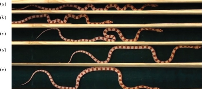
Wave-like shape of a snake under parallel lateral constraints on a horizontal plane. The length of the snakes is 61 ± 4 cm; the radius of the snake is 1 cm; the width between constraints is respectively 2, 3, 4, 5, 6 cm from (a–e) [6]. (Online version in colour.)
Inspired by the fact that the sinusoidal morphology of a constrained crawling snake is analogous to a buckled beam, insights may be obtained by studying elastic beam buckling under two parallel lateral constraints, in particular, the formation of a rectangular wave upon contact. A theoretical framework is established in this paper, and the transition between different modes is obtained as a function of axial strain and wall spacing. The theory is compared with finite-element simulation. The buckling profiles from theory and simulation are then qualitatively related to the characteristics of the crawling snake.
2. Model and method
2.1. Theoretical model
The schematic of a two-dimensional model with linear elastic response is shown in figure 2, which is inspired by the results of Chai [3,4] and is used to represent the axial skeleton of a snake [9,10]. An elastic beam of length L0 and radius r is initially placed in the middle of two parallel walls. The beam and walls are placed on the same horizontal plane. Both ends are allowed to move freely in the y-direction, yet their rotational degree of freedom is constrained, which resembles the snake crawling behaviour. To apply axial compression, the left end of the beam is fixed in the x-direction, and the right end is pushed inwards by a displacement of ΔL. The wall is assumed rigid and kept fixed throughout, and contact friction is neglected in this model.
Figure 2.
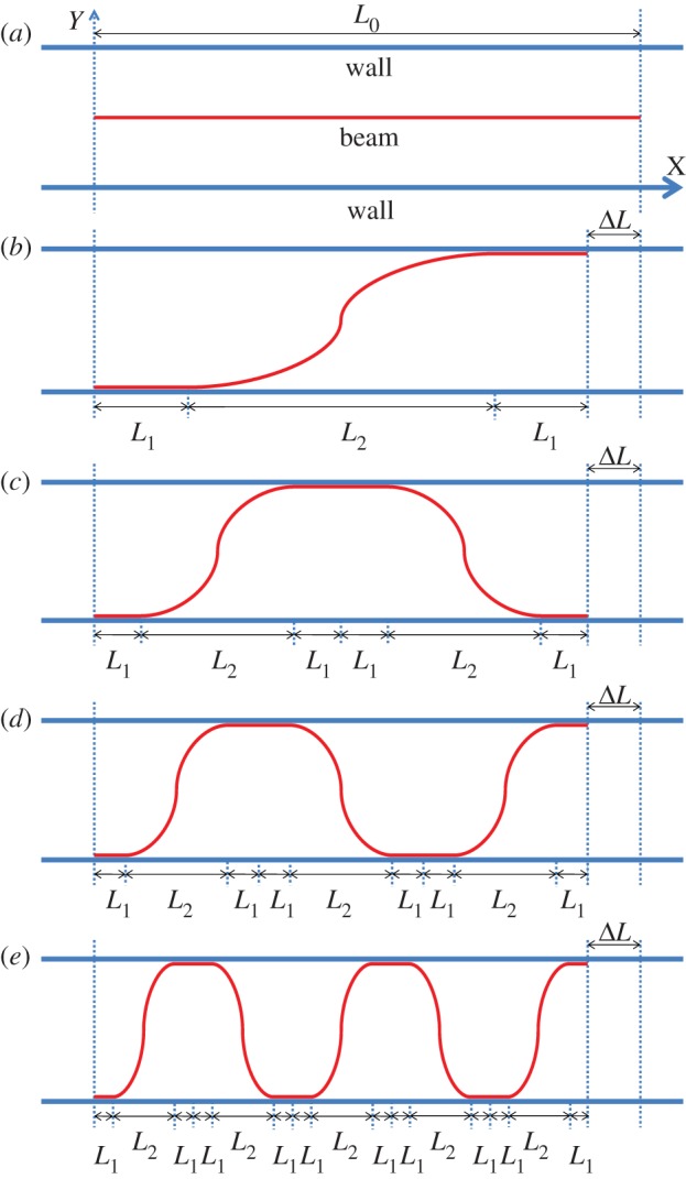
Schematic of the theoretical model and the first few buckling modes. (a) Shape of the undeformed beam; (b) buckling mode 1 of the deformed beam; (c) buckling mode 2 of the deformed beam; (d) buckling mode 3 of the deformed beam and (d) buckling mode 5 of the deformed beam. (Online version in colour.)
When the compressive strain exceeds critical strain, the beam buckles, and the buckling amplitude increases with ΔL, until the deformed beam makes contact with the wall. The deformed profile is assumed symmetric. This becomes the bifurcation mode 1 (figure 2b). The shape of mode 1 consists of three parts [3,4]: straight section L1, curved section (with projected length L2) and straight section L1. With the further increase of ΔL, the straight sections elongate, and their length will be determined in the following section through strain energy minimization. When the straight section becomes too long, it loses stability and then the entire beam bifurcates into the next mode, illustrated as mode 2 in figure 2c. Mode 2 consists of two curved sections with straight sections in between (length 2L1) and at the ends (length L1 each). With continued compression, the straight section of mode 2 may become unstable, and mode 2 bifurcates to mode 3, figure 2d, and so on to higher modes, figure 2e and beyond, with subsequent compression. Note that as the modes shift, the beam ends may jump up or down, and such a boundary condition was not explored in previous studies.
2.2. Theoretical analysis
The shape of the beam conforms to the Euler beam theory [1,3,4]:
| 2.1 |
where k2 = P/EI with P as the axial load, E is the elastic modulus and I is the moment of inertia. A is denoted as the wave amplitude, and 2A = d is the wall spacing. Taking mode 1 as an example, the contour shape of the curved section between x = L1 and x = L1 + L2 is
| 2.2 |
which is consistent with finite-element simulation results. The constraint of coefficient k in equation (2.1) satisfies
| 2.3 |
The shape of the curved sections of other modes can be described in a similar way as equation (2.2), except that the value of L2 is different in each mode. In other words, once L1 and L2 are determined (see below), the shape function of the deformed beam is obtained.
The strain energy of the beam consists of two parts in this model: bending energy which is assumed to exist only in the curved sections and compressing energy which is assumed to be uniform along the beam, and consistent with finite-element simulation. Based on equation (2.2), the bending energy of the curved segment is calculated as:
 |
2.4 |
Denoting the total length of the deformed beam as Ldeformed (which can be readily calculated using equation (2.2)), the axial strain ɛ is
| 2.5 |
And hence the compressing energy along the beam is
| 2.6 |
where a is the area of cross section for the beam.
With increasing load ΔL, beam morphology varies. Within a particular buckling mode, the beam deforms according to minimization of the total strain energy (Ebending + Ecompression). This principle, along with the geometrical constraint
| 2.7 |
can be used to deduce L1 and L2 for a given ΔL and known mode. The beam stays at the current buckling mode until one of the straight sections gets buckled according to [3]:
| 2.8 |
where S in equation (2.8) is the length of a straight section. This determines the transition point (critical ΔL) from one bifurcation mode to the next.
2.3. Finite-element simulation
In order to verify the key assumptions used in the theoretical analysis as well as validate the model, a two-dimensional finite-element method (FEM) model is established to simulate the beam buckling process under parallel constraints, using the commercial finite-element package ABAQUS. Boundary conditions of the walls and the beam are stated previously. We started this research with a three-dimensional FEM model, which was found to be consistent with the two-dimensional model with these specific geometrical constraints. So two-dimensional models were used throughout the paper. The beam is meshed by 100 two-dimensional linear beam elements, and the wall is modelled by two-dimensional linear discrete rigid elements. The mesh density is validated by mesh convergence studies.
According to the contact theory, when there is a line contact between the beam and wall, normal contact forces do not distribute uniformly throughout the contact section, but rather concentrate on both ends of the contact section. This phenomenon is used to differentiate the line contact section from the curved section in the simulation results, and thus the values of L1 and L2 can be determined in the simulation results, and compared with the theoretical predictions (see the electronic supplementary material, figure S1).
3. Results and discussion
3.1. Comparison between simulation and theoretical model
According to our model, the projected length of the curved section, L2, is an important parameter determining not only the shape of the buckled beam, but also the bending energy of the system. We did not calculate L1, because once L2 is determined, the total length of L1 is L0 − ΔL − nL2, where n indicates the buckling mode, whereas values for individual L1 vary along the beam because of the asymmetries described in §3.2. Values of L2 from theoretical analysis and simulation are compared at different nominal strain values (ΔL/L0) in figure 3, with representative geometrical values L0/d = 10, d/r = 10. As illustrated in figure 2, the beam undergoes different buckling modes as the compression proceeds (the modes are separated by vertical dot lines in figure 3, according to our theoretical model). Within a given buckling mode, L2 decreases as ΔL/L0 increases, implying that the strain energy of the beam increases with compression. Although when the mode transition occurs, L2 suddenly increases as a result of relieving compressive energy.
Figure 3.
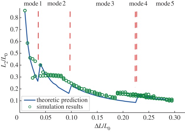
L2 for different displacement ΔL, all data are normalized by original length L0. Geometrical parameters are L0/d = 10 and d/r = 10. (Online version in colour.)
It should be remarked that mode 4 is not sketched in figure 2, and this mode is rarely observed in reality, because, when mode 3 reaches critical, it is more natural for its two straight sections to buckle simultaneously and become mode 5. This is confirmed by the FEM simulation results in figure 3.
The comparison between the theoretical model and the simulation in figure 3 shows that, whereas for most parts, the variation trend of L2 predicted by the model agrees well with the FEM simulation, the modal transition points are not consistent, especially for mode 2 and the beginning part of mode 5. In the FEM simulation, mode transition (higher-order bifurcation) occurs sooner than that in the model, the reasons for which are analysed in the following sections.
3.2. Symmetric versus non-symmetric models: upper and lower limits
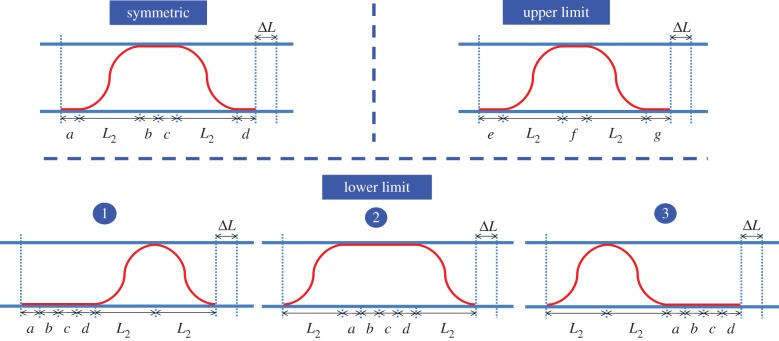
Examination of the FEM simulation results reveals that the deformed profiles are often not symmetric, in particular for mode 2 and the beginning part of mode 5. As mentioned earlier, the theoretical model is based on the assumption that the buckled beam shape is symmetric (figure 2). However, when the straight section is redistributed along the beam (while keeping its length fixed), the total strain energy would remain the same. Using mode 2 as an illustrative example, the relocation of straight sections is illustrated in figure 4, where the various sibling morphologies share identical bending and compressive strain energies.
Figure 4.
Different sibling morphologies for mode 2, symmetrical case, upper limit and lower limit, which affect its transition to the subsequent mode 3 with increasing load. (Online version in colour.)
The reshuffle of the straight sections, however, does affect the modal transition point which dictates the instability of the straight section. Such an effect of asymmetry on buckling mode transition was first noted by Chai [3] and then Pocheau & Roman [11], who provided the upper and lower limits for modal transition. In this study, figure 4 illustrates the upper limit and lower limit for the transition from mode 2 to mode 3. At a given nominal strain ΔL, the total length of the beam in the projection of the x-direction is L0 − ΔL, which means that a + b + c + d + 2L2 = e + f + g + 2L2 = L0 − ΔL for all cases in figure 4. In the symmetric case, a = b = c = d. For the upper limit case, e = f = g, so every straight section is as short as possible which makes its instability the most difficult. For the lower limit, all straight sections merge into a single straight section (there are three possible shapes for lower limit at mode 2), which becomes the easiest to buckle. Although prior theoretical analysis is based on the symmetric model, similar analyses can be carried out for the upper and lower limit cases to obtain the bounds of modal transitions. One expects that the real solution (e.g. FEM simulation, which may be sensitive to defects) is within the upper and lower bounds.
Analogous to Chai [3], a buckling mode map (figure 5) is established to predict the modal status at different ΔL/L0, which includes that from the upper and lower limits, as well as that based on the symmetric assumption. The data points for the upper limit and lower limit are slightly shifted vertically in order to differentiate themselves from the data points for the symmetric case. In general, the FEM simulation results are indeed bounded by the upper limits.
Figure 5.
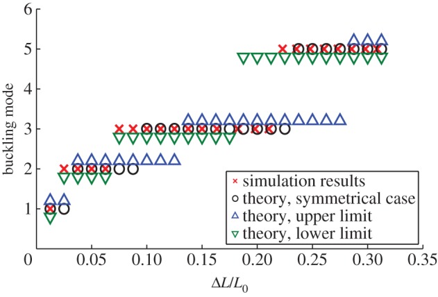
Buckling mode map for theoretical analysis and simulation with upper limit and lower limit. Geometrical parameters are L0/d = 10 and d/r = 10. (Online version in colour.)
3.3. Effect of wall spacing and implication for the crawling snake
For a flexible beam with a given nominal strain ΔL/L0, its morphological profile is determined by the geometrical parameters. For the crawling snake in figure 1, its morphology is rather distinct when the wall spacing is changed. Assume that the snake uses the same nominal strain to crawl forward, figure 6 illustrates the buckling shapes of beams with different L0/d at the same ΔL/L0 = 0.2. The data points are non-dimensionalized by amplitude d in the y-direction, and L0 in the x-direction.
Figure 6.
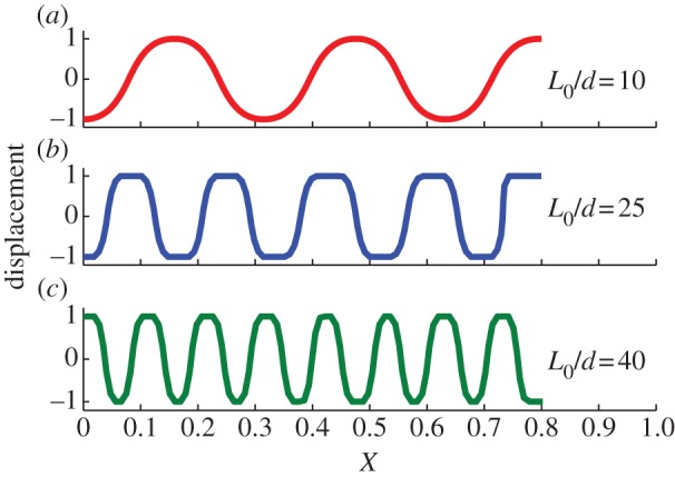
Buckling shapes of beams with different L0/d at the same ΔL/L0 = 0.2. (a,b) The beam with the same length L0/r = 100, but different d/r = 10 and d/r = 4, (c) shows the beam with length L0/r = 200 and d/r = 5. (Online version in colour.)
In general, as the wall spacing d becomes tighter, the number of curved section increases for beams with the same length at the same nominal strain. This trend is exemplified by five curved sections in figure 6a and nine curved sections in figure 6b, and it is qualitatively consistent with the shape of snake in figure 1. Meanwhile, even with a larger d/r, the beam in figure 6c shows more curved sections than figure 6b does, because, in this case, the length of the snake increases from L0/r = 100 to L0/r = 200. Therefore, the primary dimensionless geometry parameter governing the number of curved section (at a certain nominal strain) is L0/d. For beams with the same L0/d, a larger d/r postpones the transition between buckling modes.
By observing the snake between parallel walls producing a channel width of 2 cm, i.e. snake shown in figure 1a, the number of curved sections of the snake was consistently found to be 12 during the crawling process (evidence can be seen in the electronic supplementary material, video S1). The snake in a 2 cm channel is characterized by L0/d = 30.5, and it corresponds to the simulation case L0/r = 200, d/r = 7, L0/d = 28.6 in figure 7a. The head part of snake is not counted because it is much stiffer than its body, so we may take a smaller L0/d in the simulation. The deformation shape of the snake is not uniform because its movement (compressive strain) is not uniform throughout the snake's body and the radius of the snake varies from head to tail. Nevertheless, the overall number of curved sections is consistent with our theoretical analysis. In figure 7b, we also compare our model with the snake in a channel with a width of 3 cm, i.e. the snake shown in figure 1b. The snake under this circumstance is characterized by L0/d = 20.3, which is analogous to the present model with L0/r = 200, d/r = 10 and L0/d = 20. The number of curved sections of the snake is consistently 10 during the crawling process, and the present simulation results show 11 curved sections. This small discrepancy comes from the fact that the snake does not follow the concertina pattern strictly during the procession, because the snake has more lateral room to use their normal lateral undulation mode. Moreover, the body of the snake is not uniform. Therefore, a large part of snake does not touch the sidewall, as shown in figure 7b.
Figure 7.
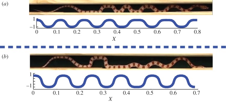
Comparison between real snake and simulation results. In (a), 12 curved sections are found in both experiments and simulations, geometrical parameters in simulations are L0/r = 200, d/r = 7 and L0/d = 28.6. In (b), 10 curved sections are found in the experiments, which corresponds to the simulation case of 11 curved sections. Geometrical parameters in simulations are L0/r = 200, d/r = 10 and L0/d = 20. (Online version in colour.)
4. Conclusions
This paper describes the buckling shape of a linear elastic beam under two lateral constraints. Owing to the unique boundary conditions of the beam ends, intriguing buckling shapes are observed which are different from that reported previously [3,4]. Our results elucidate the effects of geometrical parameters, ΔL/L0, L0/d and d/r, on the buckling shape of the beam. This study could also be of interest to the study of microtubules of the cell cytoskeleton and related systems, whose buckling behaviours are constrained by surrounding structures [12,13].
We then apply our theory to explain why crawling snakes confined in channels adapt the unique wave-like shape, and we explain qualitatively the effect of width between two constraints on the shape of snakes. Previous research has documented the shape of crawling snakes in concertina mode, and they detected alternative activation of axial muscle on two sides of the snake's body during the concertina motion [9,10]. Unlike the smooth progression of a snake in lateral undulation mode, the snake in concertina mode progresses in a two-stage approach (see the electronic supplementary material, video S1): the snake compresses the posterior of its body into several bends while keeping the anterior fixed, then the snake use the areas of contact in the posterior as an anchor and extends its anterior part in the forward direction. The snake extends its anterior part in a mode similar to lateral undulation, while our theory may effectively apply to the compression stage. For narrow channels such as figure 1a,b, the contracting snake body has to undertake the wave-like buckling shape owing to instabilities under lateral constraints as discussed in previous sections. For the wider channels such as figure 1d,e, snakes have more freedom to use their normal lateral undulation mode to crawl, even though the amplitude of undulation is confined by parallel walls [6]. So the shape of crawling snakes between lateral constraints producing a large width is actually a variation of the lateral undulation mode.
Our analysis is based on the assumption that the body of the snake is under compressive stress, which in reality is due to the muscle contraction along the snake's body. The snake contracts its axial muscles on two sides of its body alternately in the concertina progression [10], so we take the distributive contractile muscle stress as the effective compressive stress in the snake's body, which is consistent with our theoretical and numerical model. Our theory focuses on the linear elastic response of beam/snake, but the snake occasionally exhibits interesting shapes shown in figure 1c, which is a spiral-type buckling mode in the plastic regime [14]. We also observed this large deformation pattern in our simulation results, which requires future modelling effort. Furthermore, friction is essential in the lateral undulation mode as well as in the concertina mode, which adds another complexity to our model. We hope to encompass the friction between the snake and the walls, as well the friction between the snake and the horizontal ground in the future studies. The model needs to be refined toward real snake behaviours.
Our results can contribute to the belief that some intriguing behaviours in nature, be it the morphology of plants [15,16] or morphology of animals, can be explained from the perspective of solid mechanics, especially buckling phenomena. As a possible extension in future, understanding this could also lead to advancements in the design of snake robots [17] or mechanical self-assembly [18].
Acknowledgements
We thank David Hu for the experiments with snakes. The study is supported by the National Natural Science Foundation of China (11172231), DARPA (W91CRB-11-C-0112) and the National Science Foundation (CMMI-0643726). J.X. is also supported by the China Scholarship Council.
References
- 1.Timoshenko SP, Gere JM. 2009. Theory of elastic stability, 2nd reprint edn New York, NY: Dover Publications [Google Scholar]
- 2.Adan N, Sheinman I, Altus E. 1994. Post-buckling behavior of beams under contact constraints. J. Appl. Mech. Trans. ASME 61, 764–772 10.1115/1.2901552 (doi:10.1115/1.2901552) [DOI] [Google Scholar]
- 3.Chai H. 1998. The post-buckling response of a bi-laterally constrained column. J. Mech. Phys. Solids 46, 1155–1181 10.1016/s0022-5096(98)00004-0 (doi:10.1016/s0022-5096(98)00004-0) [DOI] [Google Scholar]
- 4.Chai H. 2002. On the post-buckling behavior of bilaterally constrained plates. Int. J. Solids Struct. 39, 2911–2926 10.1016/s0020-7683(02)00253-6 (doi:10.1016/s0020-7683(02)00253-6) [DOI] [Google Scholar]
- 5.Shan W, Chen Z. 2013. Mechanical instability of thin elastic rods. J. Postdoctoral Res. 1, 1–8 [Google Scholar]
- 6.Marvi H, Hu DL. 2012. Friction enhancement in concertina locomotion of snakes. J. R. Soc. Interface 9, 3067–3080 10.1098/rsif.2012.0132 (doi:10.1098/rsif.2012.0132) [DOI] [PMC free article] [PubMed] [Google Scholar]
- 7.Hu DL, Nirody J, Scott T, Shelley MJ. 2009. The mechanics of slithering locomotion. Proc. Natl Acad. Sci. USA 106, 10 081–10 085 10.1073/pnas.0812533106 (doi:10.1073/pnas.0812533106) [DOI] [PMC free article] [PubMed] [Google Scholar]
- 8.Guo ZV, Mahadevan L. 2008. Limbless undulatory propulsion on land. Proc. Natl Acad. Sci. USA 105, 3179–3184 10.1073/pnas.0705442105 (doi:10.1073/pnas.0705442105) [DOI] [PMC free article] [PubMed] [Google Scholar]
- 9.Gray J. 1946. The mechanism of locomotion in snakes. J. Exp. Biol. 23, 101–120 [DOI] [PubMed] [Google Scholar]
- 10.Jayne BC. 1988. Muscular mechanisms of snake locomotion: an electromyographic study of the sidewinding and concertina modes of Crotalus cerastes, Nerodia fasciata and Elaphe obsoleta. J. Exp. Biol. 140, 1–33 [DOI] [PubMed] [Google Scholar]
- 11.Pocheau A, Roman B. 2004. Uniqueness of solutions for constrained elastica. Physica D: Nonlinear Phenom. 192, 161–186 10.1016/j.physd.2003.12.013 (doi:10.1016/j.physd.2003.12.013) [DOI] [Google Scholar]
- 12.Brangwynne CP, MacKintosh FC, Kumar S, Geisse NA, Talbot J, Mahadevan L, Parker KK, Ingber DE, Weitz DA. 2006. Microtubules can bear enhanced compressive loads in living cells because of lateral reinforcement. J. Cell Biol. 173, 733–741 10.1083/jcb.200601060 (doi:10.1083/jcb.200601060) [DOI] [PMC free article] [PubMed] [Google Scholar]
- 13.Shan WL, Chen Z, Broedersz CP, Gumaste AA, Soboyejo WO, Brangwynne CP. 2013. Attenuated short wavelength buckling and force propagation in a biopolymer-reinforced rod. Soft Matter 9, 194–199 10.1039/C2SM26974K (doi:10.1039/C2SM26974K) [DOI] [Google Scholar]
- 14.Chai H. 2008. On optimizing crash energy and load-bearing capacity in cellular structures. Int. J. Solids Struct. 45, 528–539 10.1016/j.ijsolstr.2007.08.001 (doi:10.1016/j.ijsolstr.2007.08.001) [DOI] [Google Scholar]
- 15.Yin J, Cao Z, Li C, Sheinman I, Chen X. 2008. Stress-driven buckling patterns in spheroidal core/shell structures. Proc. Natl Acad. Sci. USA 105, 19 132–19 135 10.1073/pnas.0810443105 (doi:10.1073/pnas.0810443105) [DOI] [PMC free article] [PubMed] [Google Scholar]
- 16.Gerbode SJ, Puzey JR, McCormick AG, Mahadevan L. 2012. How the cucumber tendril coils and overwinds. Science 337, 1087–1091 10.1126/science.1223304 (doi:10.1126/science.1223304) [DOI] [PubMed] [Google Scholar]
- 17.Hirose S. 1993. Biologically inspired robots: snake-like locomotors and manipulators. Oxford, UK: Oxford University Press [Google Scholar]
- 18.Chen X, Yin J. 2010. Buckling patterns of thin films on curved compliant substrates with applications to morphogenesis and three-dimensional micro-fabrication. Soft Matter 6, 5667. 10.1039/c0sm00401d (doi:10.1039/c0sm00401d) [DOI] [Google Scholar]


