Abstract
Sedimentation velocity is a classical method for measuring the hydrodynamic, translational friction coefficient of biological macromolecules. In a recent study, comparing various analytical ultracentrifuges, we have shown that external calibration of the scan time, radial magnification, and temperature are critically important for accurate measurements (Anal. Biochem., 2013, doi: 10.1016/j.ab.2013.05.011). To achieve accurate temperature calibration, we have introduced the use of an autonomous miniature temperature logging integrated circuit (Maxim Thermochron iButton ™) that can be inserted in an ultracentrifugation cell assembly and spun at low rotor speeds. In the present work, we developed an improved holder for the temperature sensor located in the rotor handle. This has the advantage of not reducing the rotor capacity and allows for a direct temperature measurement of the spinning rotor during high-speed sedimentation velocity experiments up to 60,000 rpm. We demonstrate the sensitivity of this approach by monitoring the adiabatic cooling due to rotor stretching during rotor acceleration, and the reverse process upon rotor deceleration. Based on this, we developed a procedure to approximate isothermal rotor acceleration for better temperature control.
Keywords: Sedimentation velocity, temperature calibration
Introduction
Analytical ultracentrifugation (AUC) is one of the classical biophysical methods for the study of macromolecular size and shape, their interactions, and size-distribution in free solution [1]. Advances in computational data analysis have greatly facilitated the precise determination of sedimentation coefficients and the interpretation of translational friction parameters, as determined by sedimentation velocity (SV), has become of high interest in the context of structure-based hydrodynamic modeling [2,3], and multi-method modeling of small angle scattering data [4].
Accurate knowledge of the solution temperature is critical for an absolute determination of these hydrodynamic parameters, mainly due to the strongly temperature-dependent viscosity of water. Unfortunately, a measurement of the sample solution temperature in a spinning rotor is non-trivial and many methods have been developed during the long history of AUC. These include devices based on calibrated thermocouples [1,5,6], methods based on the observation of the melting point of solids [7,8], radiometers [9,10], and thermochromic solutions [11]. A radiometer is currently implemented in the ProteomeLab analytical ultracentrifuge (Beckman Coulter, Indianapolis, IN).
In a recent study comparing ten different analytical ultracentrifuges, we found that the sedimentation coefficient of monomeric bovine serum albumin (BSA) differed by as much as 15%, depending on the instrument used [12]. This contrasts to the precision of ~0.1% when data are acquired side-by-side in the same experiment and on the same instrument [12,13]. To account for this huge discrepancy, we developed methods for the external calibration of scan time, radial magnification, and temperature, and demonstrated that the combined application of corrections from these experimental dimensions leads to a precision equivalent to that observed for a single instrument. We have introduced the use of a miniaturized integrated circuit with onboard memory (Maxim Thermochron iButton ™) that can log the rotor temperature as a function of time and found that measured temperatures for different centrifuges, at a set point of 20 °C, spanned a range of more than 4 °C, accounting for errors in excess of 10% in the hydrodynamic parameters. We have independently validated the correctness of the temperature readings through a sedimentation coefficient standard under control of other factors [12].
Even though this temperature probe is both inexpensive and simple to use, it is susceptible to mechanical damage when subjected to high-g forces, which are generally applied in AUC experiments. To circumvent this issue, temperature measurements using the iButton are necessarily carried out at low rotor speeds, requiring a separate experiment from the usually high-speed SV run. Furthermore, even when rotor speeds are compatible, a drawback of this design is that the iButton holder occupies a separate rotor position, lowering the sample capacity. In the present work we describe a modification of the approach that addresses these limitations and allows the external temperature measurement to take place during any AUC experiment.
Materials and Methods
Temperature measurements were carried out using Maxim Thermochron iButtons (Maxim Integrated Products, San Jose, CA, USA) as described [12]. Briefly, DS1922L iButtons with 11-bit resolution, corresponding to 0.0625 °C increments, and a range from −10 °C to +65 °C, were calibrated with a NIST-certified reference thermometer P795 (ThermoWorks, Lindon, UT, USA) accurate to ± 0.015 °C. For calibration, the iButton and the thermometer probe of the reference thermometer were brought to equal temperature in an aluminum iButton holder packed in thermal beads and immersed in a water bath, at temperatures of 0 °C, 10 °C, 21 °C, and 30 °C. Accuracy of the iButton reading was estimated to be better than 0.2 °C, with repeatability generally ~ 0.1 °C or better. For comparison, iButtons calibrated by the vendor (Thermodata Corporation, Marblehead, MA, USA) were used in some experiments.
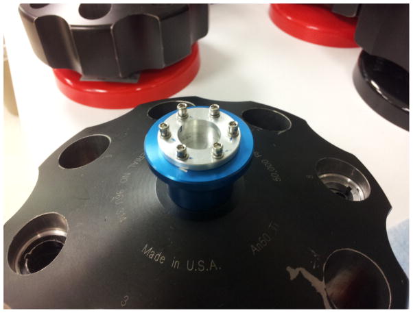
Analytical ultracentrifugation experiments were conducted in an Optima XL-A or ProteomeLab analytical ultracentrifuge (Beckman Coulter, Indianapolis, IN, USA), equipped with An-50 Ti and An-60 Ti analytical rotors. A low-speed iButton cell assembly fitting the rotor hole was machined by the NIH machine shop in-house as described [12]. Also in-house, a high-speed iButton placement assembly with an upper cup to hold the iButton was designed to replace the aluminum handle of the AUC rotor. This was centered on the axis of rotation, and contained a ring with screws to secure the iButton on the rotor (Figure 1). A detailed drawing can be found in the Supplementary Material.
Figure 1.
Photograph of the iButton holder in a modified rotor handle. A central cup is machined in a regular rotor handle such that the iButton is held in firm thermal contact with the rotor. It is secured in place with an aluminum ring fastened to the rotor handle with screws.
Sedimentation velocity experiments with BSA were carried out as described previously [12]. Briefly, a cell assembly containing 400 μl of BSA (Sigma-Aldrich, St. Louis, MO, USA, cat. No. 7030) at a concentration of 0.5 mg/ml in phosphate buffered saline (PBS) in the sample sector of a standard 12 mm pathlength Epon charcoal centerpiece, with PBS in the reference sector, was inserted in an 8-hole An-50 Ti rotor, temperature equilibrated to 20 °C at rest for at least 2 hours in the rotor chamber, and then accelerated to 50,000 rpm. For experiments in which the rotor speed was accelerated at 1,000 rpm per 90 s or less, the rotor speed was changed manually from rest in 1,000 rpm increments according to a schedule with equidistant time intervals. In the case of the slowest acceleration, the rotor speed profile with time was programmed as an equilibrium method in 1,000 rpm increments. Absorbance data were acquired at a wavelength of 280 nm, in time intervals of 3 min, with a radial increment of 0.003 cm. Data were analyzed in SEDFIT (https://sedfitsedphat.nibib.nih.gov/software) with the c(s) model [14], using numerical solutions of the Lamm equation [15] that incorporate a constant rotor acceleration [16], as implicitly determined by the elapsed time and elapsed ω2t entries of the file headers. Scan time corrections were applied using the operating system file time stamps [12,17]. Unless mentioned otherwise, apparent molar mass values were based on an ad hoc approximation of 0.27 for the buoyancy factor. Results were plotted using GUSSI (http://biophysics.swmed.edu/MBR/software.html).
Sedimentation velocity experiments on BSA were also carried out at various temperatures to determine the dependence of the actual rotor temperature. The rotor, sample and iButton were equilibrated overnight in the AUC chamber at an initial temperature of 4 °C and data were subsequently collected at 50,000 rpm. Following data collection, which required at most 5.5 hours, the iButton was reset and the BSA sample gently resuspend. The rotor, sample and iButton were then equilibrated overnight at 10 °C for the next velocity experiment. The process was repeated on the same instrument in increments of 5 °C until a temperature of 35 °C was reached. A final analysis at 20 °C was then carried out. c(s) analyses of the experimental series at different temperatures were performed utilizing temperature appropriate PBS buffer densities and viscosities, and BSA partial specific volumes determined in SEDNTERP (http://sednterp.unh.edu/).
AUC experiments utilizing a fluorescence optical detection system were conducted in an Optima XL-A instrument equipped with an FDS system (Aviv Biomedical, Lakewood, NJ, USA). To ascertain the potential effect of operating the 10 mW laser located inside the rotor chamber, we accelerated the rotor with the iButton loaded in the rotor handle to 50,000 rpm, and, after temperature stabilization for ~ 30 min, cycled the laser on and off in 15 min intervals for several times. After stopping the run, the logged temperature was examined for any deviations from the equilibrium temperature.
Results
The rotor handle is an attachment made from aluminum and screwed into the titanium body of the rotor. As it is located in the center of rotation, the centrifugal forces are minimal and thus ideal for placement of the iButton. The experimental placement of the iButton into a modified rotor handle was found to be mechanically stable over many runs at rotor speeds up to 60,000 rpm without discernible damage to the iButton and without compromising the temperature measurements and memory (Figure 1).
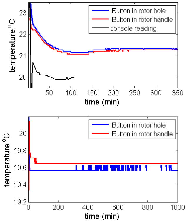
In order to test how the placement of the temperature sensor relative to the location of the samples and the rotor drive affects the temperature reading, we conducted experiments with two iButtons, one in the rotor hole placed in the previously developed assembly, and the other in the rotor handle. The top panel of Figure 2 shows the time-course of temperature readings for both loggers, highlighting the early equilibration phase. The bottom panel of Figure 2 shows a repeat experiment conducted in a different instrument with data from a longer time window. Even though in these experiments the two iButtons are in different places, we observe a very similar time-course of the temperature readings, providing further validation that the reading of the iButtons in both placements reflect the same rotor temperature. Interestingly, the time-course of temperature equilibration as observed from the console temperature readings (black trace in the Top Panel of Figure 2) is similar in shape to both iButton readings, but appears to reach the steady-state faster.
Figure 2.
Comparison of temperature readings of iButtons in the cell assembly adapter (blue) and the rotor handle adapter (red), with temperature set-point on the centrifuge console of 20 °C. Top: Short-time behavior in instrument Shemp, without pre-equilibration of the rotor, spinning at 1,000 rpm. Bottom: Long-time traces in instrument Momo, pre-equilibrating in the rotor chamber at rest, followed by acceleration to 3,000 rpm at 940 min.
To explore the origin of the remaining differences of ~ 0.1 °C in the iButton traces of Figure 2, four iButtons were placed next to each other on top of a resting rotor and temperature equilibrated two days in the evacuated AUC chamber. Readings for the in-house calibrated iButtons used in Figure 2 were 19.71 °C and 19.69 °C, and for two iButtons purchased pre-calibrated we obtained corrected values of 19.67 °C and 19.66 °C. The differences between the two sets of iButtons are comparable to the run-to-run repeatability, which is usually within 1 bit, i.e. 0.06°C. Thus, the accuracy of the temperature measurement appears to be ~ 0.1 °C, and compared to this the slightly different readings in Figure 2 may not be a result of the different positions.
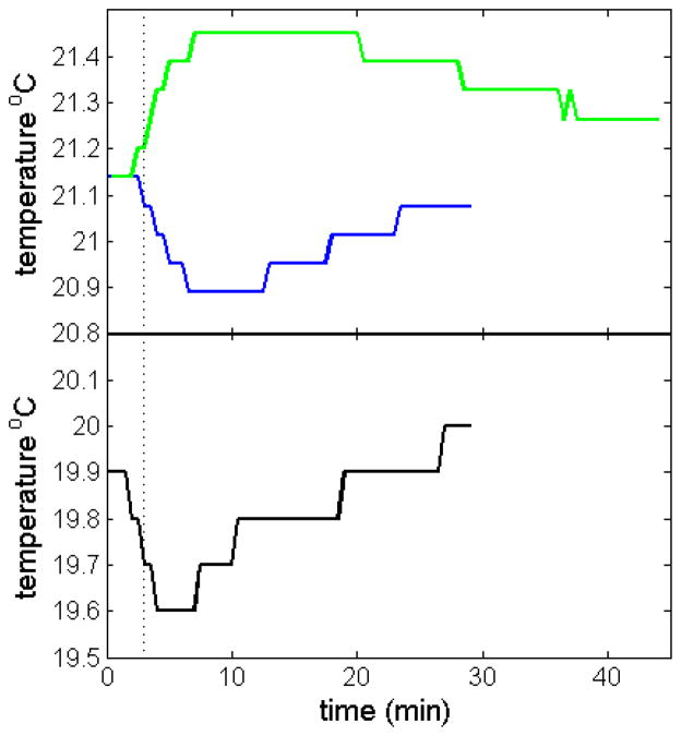
Next, we exploited the capability of the iButton rotor handle holder to measure temperatures at high rotor speeds. After the customary temperature equilibration of the rotor at rest with an instrument temperature set-point of 20 °C, we accelerated the rotor to 50,000 rpm. Figure 3 shows the temperature readings as a function of time, acquired in 30 sec intervals (blue line). After a transient drop, lasting ~ 10 min, the rotor temperature gradually recovers to a value close to that prior to acceleration, which is attained after ~ 30 min. This is similar to the temperature readings from the instrument radiometer displayed in the console (Figure 3, black line), even though these are offset, as previously shown. Interestingly, the radiometer readings shown at the console display reach the minimum more quickly than the iButton readings. During the run the temperature was found to be very stable, usually without any fluctuations in the iButton readings. After initiation of rotor deceleration, an increase of the rotor temperature was observed (Figure 3, green line). It returns more slowly to the set point, likely due to weaker heat transfer during rotor cooling as compared to heating. In the case of the FDS-AUC, we verified during the run at 50,000 rpm that operation of the FDS laser had no discernible influence on the measured rotor temperature at both 10 °C and 20 °C (data not shown).
Figure 3.
Rotor temperature measurement after start of acceleration to 50,000 rpm (Top, blue), and after deceleration of the rotor (Top, green) in instrument Shemp. For comparison, the console temperature reading after start of acceleration is shown in the lower plot (Bottom, black). Data were acquired with the iButton in the rotor handle of an An-50 Ti rotor, with both acceleration and deceleration at maximum setting. For the acceleration phase, the time when full speed of 50,000 rpm is reached is indicated as dotted vertical line.
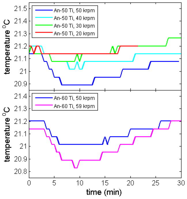
A transient drop in temperature upon rotor acceleration is well-known to arise from adiabatic cooling of the rotor due to stretching [10], reflecting the positive coefficient of thermal expansion of the rotor material. As the magnitude of this effect depends on the rotor speed, we conducted experiments at various rotor speeds and with the two different types of analytical rotors (Figure 4). As expected, smaller transient temperature drops are observed when accelerating the rotor from rest to lower rotor speeds. Because the instrument has the capability for rotor heating and cooling to compensate for rotor temperature changes, the same final rotor temperatures were achieved independent of rotor speed.
Figure 4.
Measured adiabatic cooling at different rotor speeds (in instrument Shemp), for the An-50 Ti eight-hole rotor (Top) and the An-60 Ti four-hole rotor (Bottom).
Since the rotor acceleration is approximately 280 rpm/sec and the stretching-induced rotor temperature changes are instantaneous with stretching, we can calculate that the maximum temperature change for an experiment at 50,000 rpm will occur after ~ 3 min after start of acceleration. Since the amount of stretching imposed to the rotor is proportional to the distance from the center of rotation, it must create a temperature gradient within the rotor. The maximum deflection of the measured temperature from the equilibrium temperature was centered at ~ 10 min after start of acceleration. From this, we estimate that the temperature equilibration within the rotor inclusive the iButton in the center of the rotor handle occurs with a time constant on the order of ~ 5 min. Recovery of the set temperature is slightly slower.
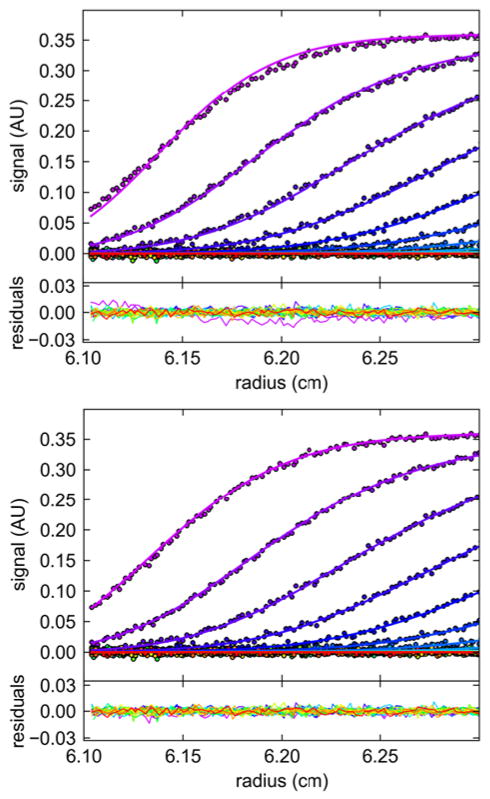
In principle, it seems desirable to conduct rotor acceleration as an isothermal, rather than adiabatic, process. We hypothesized this could be approximated by slowing down the rotor acceleration sufficiently such that heating of the rotor can compensate for the heat losses due to rotor stretching. Based on the apparent time constant of heat flow estimated above, we estimated initially that a 10-fold slower acceleration should reduce the temperature drop significantly. Unfortunately the acceleration profiles on the ProteomeLab analytical ultracentrifuges only allow for the modulation of the length of an initial start phase, followed by a standard acceleration. Therefore, we approximated a slower constant acceleration in a discrete schedule of 50 steps, starting at rest and increasing the rotor speed by 1,000 rpm every minute. The resulting time-course of the rotor temperature reading is shown in Figure 5 (cyan dashed line). An even slower acceleration with 1,000 rpm per 90 sec resulted in the temperature profile shown in Figure 5 as magenta solid line. The sharp transient drop in temperature has diminished, now showing a much shallower temperature drop extending over a longer period of time, although a small drop can still be discerned. However, when the acceleration was further slowed to steps of 1,000 rpm per 3 min (set up as ‘equilibrium method’ in the ProteomeLab GUI), an isothermal experiment was successfully approximated within the error of the temperature measurement (Figure 5, red solid line). Despite the same set point of 20 °C the equilibrium rotor temperature for this experiment is ~0.3 °C lower. This is uncharacteristic as the run temperature in a given instrument is highly reproducible. Nevertheless, as previously noted [12], sudden, adventitious changes can occur and in the present case this drop in temperature coincides with an instrument service carried out between the experiments. In all subsequent experiments, temperatures consistent with the new, slightly lower, rotor temperature were measured (data not shown).
Figure 5.
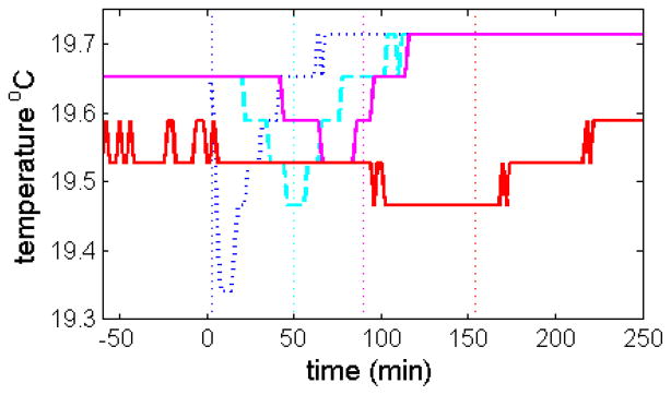
Measured time-course of temperature during rotor acceleration to 50,000 rpm in the same instrument (Momo) with either standard maximum acceleration of 280 rpm/sec (blue dottted line), with a slow acceleration of 16.7 rpm/sec manually approximated by a step-wise change of rotor speed at a rate of 1,000 rpm per minute (cyan dashed line), with an acceleration of 11.1 rpm/sec approximated in steps of 1,000 rpm per 90 sec (magenta solid line), and with an acceleration of 5.6 rpm/sec approximated in steps of 1,000 rpm per 180 sec (red solid line). The vertical dotted lines indicate the time-points when 50,000 rpm was reached in the respective experiments.
In the same experiments, sedimentation velocity data of our reference BSA sample were acquired (Figure 6). As described previously [12], BSA is an excellent sedimentation coefficient standard when used in conjunction with the c(s) analysis, which allows for baseline-resolution of the monomer species, thereby eliminating bias from the BSA dimer and higher oligomers in the analysis. For calculating the Lamm equation solutions underlying the sedimentation coefficient distribution c(s) in SEDFIT we used two options: (1) The historic approach to correct for rotor acceleration in the analysis by treating the rotor speed as a constant ωfinal, compensated for by an effective sedimentation time teff based on the recorded values of ∫ ω(t)2 dt in the scan file headers, following . For example, for the data at 11.1 rpm/sec, this led to a best-fit sedimentation coefficient for the BSA monomer of s = 4.279 S. (2) Alternatively, an analysis with explicit simulation of constant rotor acceleration ω(t), the duration and slope of which is calculated from the difference in the elapsed time t and ∫ ω(t)2 dt entries of the scan files (the default in SEDFIT) was carried out. This led to a very similar s-value of 4.253 S. However, with the ‘effective sedimentation time’ approach (1), the initial diffusional broadening of the cell was not well described (Figure 6, Top) and diffusion overall was over-estimated, leading for the experiment at 1,000 rpm/min to an Mapp estimate of only 55.1 kDa for the BSA monomer, whereas the explicit modeling of rotor acceleration (2) led to excellent fits throughout, with a value for Mapp of 64.2 kDa, highly consistent with the calculated molar mass based on its amino acid sequence (66.4 kDa). This difference is exacerbated with the slower acceleration of 5.6 rpm/sec (1,000 rpm/3 min), where the ‘effective sedimentation time’ approach resulted in a best-fit estimate of 49.0 kDa, whereas the explicit modeling of rotor acceleration yielded a value of 66.4 kDa (data not shown), fortuitously coinciding with the sequence molar mass.
Figure 6.
Sedimentation boundaries of BSA as acquired in the intermediate slow acceleration experiment at 1,000 rpm/min (symbols), modeled with the c(s) method, either accounting only for an effective sedimentation time with instantaneous acceleration based on the elapsed ω2t (Top), or accounting for a continuous acceleration based on true elapsed times (Bottom). To highlight deviations in the data fit closest to the mensicus, the radial range was constrained to the nearest 2 mm.
To determine whether the observed differences between the measured iButton temperature and that set on the AUC console depend on the temperature at which the sedimentation experiment is carried out, we implemented a series of experiments at temperatures ranging from 4 to 35 °C. We observed a fairly uniform temperature difference of 0.2–0.3 °C between the set temperature and the iButton reading (Table 1), suggesting that this would be a feature of most instruments. Interestingly, we observed a fairly uniform temperature decrease of 0.3–0.4 °C on acceleration to 50,000 rpm, indicating that the extent of adiabatic cooling is independent of the rotor temperature. Furthermore, the recovery to the equilibrium operating temperature occurred on the same time-scale for all temperatures (data not shown). Based on the absorbance and interference temperature data, we obtain a corrected s20,w of 4.41 S with a standard deviation of 0.60 % and an estimated molar mass of 66.3 kDa with a standard deviation of 2.4 kDa (Table 1).
Table 1.
Temperature dependence of the sedimentation operating temperaturea
| XL-I set temperature (°C) | iButton operating temperature (°C) | BSA monomer s (S) | BSA monomer s20,w (S) | estimated molar mass (kDa) |
|---|---|---|---|---|
|
| ||||
| 4 | 4.151 | 2.792 | 4.412 | 66.2 |
| 10 | 10.184 | 3.314 | 4.405 | 67.0 |
| 15 | 15.206 | 3.783 | 4.404 | 66.1 |
| 20 | 20.223 | 4.284 | 4.416 | 67.8 |
| 25 | 25.235 | 4.786 | 4.410 | 66.1 |
| 30 | 30.305 | 5.355 | 4.431 | 66.6 |
| 35 | 35.307 | 5.914 | 4.431 | 66.3 |
| 20 | 20.286 | 4.286 | 4.414 | 65.8 |
Absorbance (280 nm) and interference (655 nm) sedimentation data were collected at 50,000 rpm and analyzed in terms of a c(s) distribution using iButton temperature parameters for the buffer density, viscosity and BSA partial specific volume. Sedimentation cofficients and estimated molar masses for the BSA monomer shown are based on the absorbance data. These data are only corrected for time and temperature.
Discussion
An accurate determination of the rotor temperature is very important, as in a study of 10 instruments running at the same set-point of 20 °C we have found temperature deviations of 4 °C, with corresponding solvent viscosity changes spanning a range of 10% [12]. This uncertainty is significantly above the accuracy of ±0.5 °C specified by the manufacturer, and far above the accuracy of 0.1 °C stated by Laue and Stafford [18]. Thus, deviations between the nominal and the actual rotor temperature represent a very significant source of systematic error, and are of major concern when conducting hydrodynamic experiments. A multi-laboratory benchmark study to explore the wider prevalence of temperature (and other) calibration errors is currently underway. While these data are still being collected, we believe routine periodic testing of the temperature and radial calibrations with a sedimentation standard are essential, and we have therefore embarked on the development of practical procedures to accomplish such reference experiments.
The main problem of rotor temperature measurement in analytical ultracentrifugation is the transfer of information from the spinning rotor into the laboratory. Systems have been developed that were based on electrical conductance [6,19], optical scanning [8], thermal infrared radiation [9,10], and radio telemetry [20]. Taking advantage of recent developments in integrated circuits, it has become possible to omit any information transfer from the spinning rotor, and instead store the measurements for later retrieval. The Thermochron iButton is such a miniaturized integrated circuit for autonomous temperature logging with on-board memory and battery. It is widely used in various scientific and industrial applications, ranging from body temperature measurements of animals [21,22], to geological applications in volcano monitoring [23] and quality control in industrial shipping and warehousing [24].
The iButton approach to AUC rotor temperature measurement is direct, low-cost, easy to apply, and highly reproducible. We have previously shown how the iButton can be applied to the measurement of ultracentrifugal rotor temperature [12], with the aid of a custom made cell assembly to fit into a rotor hole. In the present work we have improved the application with a modified rotor handle design, such that the iButton can be used during actual sedimentation velocity experiments at high rotor speeds, without compromising the number of samples that can be studied. In this manner, accurate temperature measurements can be easily accomplished as part of the routine experimental protocol.
We found that both iButton positions provide equivalent readings, with deviations of < 0.1 °C, likely reflecting the accuracy of the initial calibration, although small temperature gradients within the rotor cannot be ruled out. Temperature errors of 0.1 °C will lead to aqueous viscosity changes of ~ 0.23%, which is ~ 3 fold less than the standard deviation of s-values measured in different instruments after calibration [12], and therefore considered tolerable. Comparing the console temperature readings with the rotor temperature reading from the iButtons either placed in the new rotor handle location, or in the cell assembly adapter in the rotor hole, we observed the previously reported instrument-dependent offsets from instrument calibration errors [12]. There was no indication of a dependence of this mismatch between iButton temperature and console temperature on rotor speed.
Interestingly, comparing the time-course of temperature readings, there also appears to be a time-lag (Figure 2 and Figure 3), likely caused by temperature differences of the internal rotor temperature (recorded by the iButtons) and the rotor surface (recorded by the instrument radiometer). This is also consistent with the expectation that rotor acceleration will cause more adiabatic cooling at the highest radii due to the higher centrifugal stresses, where the radiometer is recording, as compared to regions closer to the rotor center. This observation supports our previous observations that better SV results are obtained when the rotor temperature equilibration period is carried out at least 1 hour past the time when the console temperature reaches the set point, as described in the standard protocol [25].
As shown in the present work, the sensitivity of the high-resolution iButtons is sufficient to clearly resolve the temperature drop from adiabatic cooling of the rotor first described by Waugh & Yphantis [10] and independently confirmed by Biancheria & Kegeles [8]. As pointed out by Gropper & Boyd [19], due to the ~ 3 fold higher stiffness of titanium rotors as compared to aluminum rotors, the magnitude of the effect is smaller than when initially discovered by Waugh & Yphantis. An opposing effect of pressure-induced heating of the base of the solution column was predicted by Mijnlieff et al. [26], amounting to a gradient of a few tens of °C per centimeter for aqueous columns at high rotor speeds. Simultaneous density gradients from solvent compression stabilize the solution column against convection. Nevertheless, it would seem advantageous to carry out the rotor acceleration in an isothermal mode rather than the traditional adiabatic one, if it was possible. This may be an advantage, for example, for experiments that are very sensitive to low level convection, such as trace oligomer determination [27].
Hypothesizing that an SV experiment closer to isothermal state may be achieved by slower rotor acceleration, such that heat flow from the instrument temperature control can compensate for the adiabatic cooling, we have conducted an explorative set of experiments and demonstrated the potential for isothermal acceleration. Not surprisingly, with a slower acceleration, problems in the historic approach of using an ‘effective sedimentation time’ solely from the elapsed integral ∫ ω(t)2 dt, which is accurate for sedimentation but not diffusion, are highlighted. Therefore, we maintained an approximately constant acceleration, such that we could take advantage of the readily available Lamm equation solutions in SEDFIT, which, by default, account for constant acceleration to more faithfully model the sedimentation data. Besides this proof of principle, we did not pursue other acceleration schedules, such as profiles with constant dω2/dt, which may be advantageous in generating a constant rate of cooling, or the inclusion of scans from intermediate rotor speeds to alleviate the delay in the onset of scanning, which may be the subject of future work.
In the context of the present study, these isothermal experiments emphasize the precision and reproducibility of the iButton temperature measurements when the probe is located in the rotor handle, and its potential utility for improved experimental designs. The observation of an adventitious temperature change, coincident with a centrifuge service, between sets of experiments with otherwise highly reproducible instrument performance clearly demonstrates the need to independently monitor the instrument temperature on a routine basis, at least when hydrodynamic parameter are to be compared or interpreted on an absolute scale. This is greatly facilitated by the rotor handle design for the iButton, which only requires a minimal setup time, is of low cost, and does not impact the normal workflow and experimental design.
Supplementary Material
Acknowledgments
This work was supported by the Intramural Research Programs of the National Institute of Biomedical Imaging and Bioengineering, and the National Institute of Diabetes and Digestive and Kidney Diseases.
Footnotes
Publisher's Disclaimer: This is a PDF file of an unedited manuscript that has been accepted for publication. As a service to our customers we are providing this early version of the manuscript. The manuscript will undergo copyediting, typesetting, and review of the resulting proof before it is published in its final citable form. Please note that during the production process errors may be discovered which could affect the content, and all legal disclaimers that apply to the journal pertain.
References
- 1.Svedberg T, Pedersen KO. The ultracentrifuge. Oxford University Press; London: 1940. [Google Scholar]
- 2.Aragon SR. Recent advances in macromolecular hydrodynamic modeling. Methods. 2011;54:101–14. doi: 10.1016/j.ymeth.2010.10.005. [DOI] [PMC free article] [PubMed] [Google Scholar]
- 3.Ortega A, Amorós D, García de la Torre J. Prediction of hydrodynamic and other solution properties of rigid proteins from atomic- and residue-level models. Biophys J. 2011;101:892–8. doi: 10.1016/j.bpj.2011.06.046. [DOI] [PMC free article] [PubMed] [Google Scholar]
- 4.Perkins SJ, Nan R, Li K, Khan S, Abe Y. Analytical ultracentrifugation combined with X-ray and neutron scattering: Experiment and modelling. Methods. 2011;54:181–99. doi: 10.1016/j.ymeth.2011.01.004. [DOI] [PubMed] [Google Scholar]
- 5.Robinson TK, Beams JW. Radio Telemetering from Magnetically Suspended Rotors. Rev Sci Instrum. 1963;34:63. [Google Scholar]
- 6.Ecker PG, Blum J, Hiatt CW. A Device for the Measurement of Rotor Temperature in the Air-Driven Ultracentrifuge. Rev Sci Instrum. 1949;20:799. doi: 10.1063/1.1741393. [DOI] [PubMed] [Google Scholar]
- 7.Cecil R, Ogston AG. The accuracy of the Svedberg oil-turbine ultracentrifuge. Biochem J. 1948;43:592–8. doi: 10.1042/bj0430592. [DOI] [PMC free article] [PubMed] [Google Scholar]
- 8.Biancheria A, Kegeles G. Thermodynamic measurements of ultracentrifuge rotor temperature. J Am Chem Soc. 1954;76:3737–3741. [Google Scholar]
- 9.Rowe AJ, Khan GM. Determination of Corrected Sedimentation Coefficient at Different Temperatures Using the MSE Analytical Ultracentrifugation. Anal Biochem. 1972;45:488–497. doi: 10.1016/0003-2697(72)90211-4. [DOI] [PubMed] [Google Scholar]
- 10.Waugh DF, Yphantis DA. Rotor Temperature Measurement and Control in the Ultracentrifuge. Rev Sci Instrum. 1952;23:609. [Google Scholar]
- 11.Liu S, Stafford WF. An optical thermometer for direct measurement of cell temperature in the Beckman instruments XL-A analytical ultracentrifuge. Anal Biochem. 1995;224:199–202. doi: 10.1006/abio.1995.1030. [DOI] [PubMed] [Google Scholar]
- 12.Ghirlando R, Balbo A, Piszczek G, Brown PH, Lewis MS, Brautigam CA, et al. Improving the thermal, radial, and temporal accuracy of the analytical ultracentrifuge through external references. Anal Biochem. 2013;440:81–95. doi: 10.1016/j.ab.2013.05.011. [DOI] [PMC free article] [PubMed] [Google Scholar]
- 13.Errington N, Rowe AJ. Probing conformation and conformational change in proteins is optimally undertaken in relative mode. Eur Biophys J. 2003;32:511–517. doi: 10.1007/s00249-003-0315-x. [DOI] [PubMed] [Google Scholar]
- 14.Schuck P. Size-distribution analysis of macromolecules by sedimentation velocity ultracentrifugation and lamm equation modeling. Biophys J. 2000;78:1606–1619. doi: 10.1016/S0006-3495(00)76713-0. [DOI] [PMC free article] [PubMed] [Google Scholar]
- 15.Brown PH, Schuck P. A new adaptive grid-size algorithm for the simulation of sedimentation velocity profiles in analytical ultracentrifugation. Comput Phys Commun. 2007;178:105–120. doi: 10.1016/j.cpc.2007.08.012. [DOI] [PMC free article] [PubMed] [Google Scholar]
- 16.Schuck P, Taraporewala ZF, McPhie P, Patton JT. Rotavirus nonstructural protein NSP2 self-assembles into octamers that undergo ligand-induced conformational changes. J Biol Chem. 2001;276:9679–87. doi: 10.1074/jbc.M009398200. [DOI] [PubMed] [Google Scholar]
- 17.Zhao H, Ghirlando R, Piszczek G, Curth U, Brautigam CA, Schuck P. Recorded Scan Times Can Limit the Accuracy of Sedimentation Coefficients in Analytical Ultracentrifugation. Anal Biochem. 2013;437:104–108. doi: 10.1016/j.ab.2013.02.011. [DOI] [PMC free article] [PubMed] [Google Scholar]
- 18.Laue TM, Stafford WF. Modern applications of analytical ultracentrifugation. Annu Rev Biophys Biomol Struct. 1999;28:75–100. doi: 10.1146/annurev.biophys.28.1.75. [DOI] [PubMed] [Google Scholar]
- 19.Gropper L, Boyd W. Temperature measurement and control of analytical rotors in the ultracentrifuge. Anal Biochem. 1965;11:238–45. doi: 10.1016/0003-2697(65)90011-4. [DOI] [PubMed] [Google Scholar]
- 20.Fabricant SJ. Ultracentrifuge Rotor Temperature Measurements and Control. Rev Sci Instrum. 1966;37:495. doi: 10.1063/1.1720224. [DOI] [PubMed] [Google Scholar]
- 21.Smith AD, Crabtree DR, Bilzon JLJ, Walsh NP. The validity of wireless iButtons and thermistors for human skin temperature measurement. Physiol Meas. 2010;31:95–114. doi: 10.1088/0967-3334/31/1/007. [DOI] [PubMed] [Google Scholar]
- 22.Hasselberg MJ, McMahon J, Parker K. The validity, reliability, and utility of the iButton® for measurement of body temperature circadian rhythms in sleep/wake research. Sleep Med. 2013;14:5–11. doi: 10.1016/j.sleep.2010.12.011. [DOI] [PubMed] [Google Scholar]
- 23.Likhodeev D. Temperature estimation for the most upper part of magmatic chamber of the Elbrus volcano. EGU Gen Assem Conf Abstr. 2013:1747. [Google Scholar]
- 24.Prakash G, Renold AP, Venkatalakshmi B. RFID based Mobile Cold Chain Management System for Warehousing. Procedia Eng. 2012;38:964–969. [Google Scholar]
- 25.Zhao H, Brautigam CA, Ghirlando R, Schuck P. Current methods in sedimentation velocity and sedimentation equilibrium analytical ultracentrifugation. Curr Protoc Protein Sci. 2013;7:20.12.1. doi: 10.1002/0471140864.ps2012s71. [DOI] [PMC free article] [PubMed] [Google Scholar]
- 26.Mijnlieff PF, Van Es P, Jaspers WJM. Temperature gradients in ultracentrifuge cells due to adiabatic volume changes. Recueil. 1969;88:220–224. [Google Scholar]
- 27.Gabrielson JP, Arthur KK. Measuring low levels of protein aggregation by sedimentation velocity. Methods. 2011;54:83–91. doi: 10.1016/j.ymeth.2010.12.030. [DOI] [PubMed] [Google Scholar]
Associated Data
This section collects any data citations, data availability statements, or supplementary materials included in this article.


