Abstract
We developed a novel method to fabricate monodispersed biocompatible Yb/Er or Yb/Tm doped β-NaGdF4 upconversion phosphors using polyelectrolytes to prevent irreversible particle aggregation during the conversion of the precursor (Gd2O(CO3)2•H2O:Yb/Er or Yb/Tm) to β-NaGdF4:Yb/Er or Yb/Tm. The polyelectrolyte on the outer surface of nanophosphors also provided an amine tag for PEGylation. This method is also employed to fabricate PEGylated magnetic upconversion phosphors with Fe3O4 as the core and β-NaGdF4 as a shell. These magnetic upconversion nanophosphors have relatively high saturation magnetization (7.0 emu g-1) and magnetic susceptibility (1.7×10⁻² emu g-1 Oe-1), providing them with large magnetophoretic mobilities. We have studied their magnetic properties for separation and controlled release in flow, their optical properties for cell labeling, deep tissue imaging, and their T1 and T2-weighted magnetic resonance imaging (MRI) relaxivities. The magnetic upconversion phosphors display both strong magnetophoresis, dual MRI imaging (r1=2.9 mM-1 s-1, r2=204 mM-1 s-1), and bright luminescence under 1 cm chicken breast.
Keywords: upconversion nanophosphor, magnetic nanoparticle, magnetic capture and release, deep tissue imaging, MRI
1. Introduction
Rare earth doped upconversion nanophosphors are promising bioimaging agents because of their narrow and distinct spectral emission peaks, the long optical penetration depth of their near-infrared excitation and red/near infrared emission, the negligible autofluorescence backgrounds generated at these wavelengths, and the particles' excellent photo & chemical stability and low toxicity.[1] The luminescence of upconversion nanophosphors is generated by a sequential absorption of multiple low energy photons (e.g. 980 nm near infrared light) followed by fluorescent emission of higher energy photons from the excited states. They have been applied in immunoassays,[2] chemical sensing,[3] cell labeling,[4] and small animal imaging.[1b]
Upconversion nanophosphors are primarily synthesized by hydrothermal and thermal decomposition methods.[1b] Traditional hydrothermal synthesis methods usually generate relatively monodispersed particles with controlled size and shape by incubating rare-earth precursors with fluoride salts in aqueous solutions at high temperature (150∼300 °C).[5] The thermal decomposition method involves the decomposition of organometallic reagents (e.g. rare-earth trifluoroacetates) with hydrophobic organic ligands (e.g. oleic acid, oleylamine) in a high boiling point organic solvent.[6] In order to apply these hydrophobic upconversion nanophosphors in bioimaging, their surface usually needs to be functionalized with hydrophilic ligands. This method also has been demonstrated to yield upconversion nanophosphors with well dispersed size and shape.[7]
Magnetic nanoparticles are another attractive material for bioimaging and actuation because they can be manipulated using external magnetic fields. They play an important role in biomedical applications such as bio-magnetic separation, drug delivery, MRI, and hyperthermia.[8] Much effort has been applied to designing and fabricating multifunctional magnetic upconversion nanophosphors for multimodal imaging, separation, and sensing. Previous work on magnetic upconversion nanophosphor fabrication usually involved chemically conjugating, or physically attaching, magnetic particles to upconversion nanophosphors. In 2010, Shen and coworkers fabricated magnetic upconversion phosphor by conjugating iron oxide nanoparticles on the surface of upconversion phosphors by organic ligands.[9] However, the magnetic nanophosphors synthesized in this work were relative large (∼200 nm). In 2012, Zhang and coworkers reported using magnetic upconversion nanophosphors (Fe3O4@α-NaYF4:Yb/Er, 115+/-20 nm) as drug carrier for doxorubicin.[10] However, the upconversion nanoshell is cubic phase NaYF4:Yb/Er (α-NaYF4:Yb/Er) which exhibits lower upconversion luminescent efficiency than hexagonal phase nanophosphors (β-NaYF4:Yb/Er)[11]. Cai et. al. reported a type magnetic upconversion nanophosphor (∼80 nm) with a Fe3O4 core and β-NaGdF4:Yb/Er shell to serve as a drug carrier by attaching upconversion phosphors onto iron oxide nanoparticles.[12] However, the iron oxide core needed to be coated with a thick porous silica shell in order to load small α-NaGdF4:Yb/Er nanoparticles into the porous silica shell. Meanwhile, calcination at 400 °C in H2 atmosphere was required to convert α-NaGdF4:Yb/Er to brighter luminescent β-NaGdF4:Yb/Er. Liu and co-workers recently report a method to obtain Fe3O4@β-NaGdF4:Yb/Er by thermal decomposition of organometallic reagents on iron oxide nanoparticles.[13] The obtained magnetic upconversion nanoparticles have a narrow size distribution and good size range (∼ 30 nm) to achieve long blood circulation time. However, the non-water soluble surface limits its bio-applications. To obtain biocompatible magnetic upconversion nanoparticles with long blood circulation time, the size of particles should be large enough (> 5 nm) to avoid renal filtration but small enough to minimize opsonization and reticuloendothelial system (RES) clearance.[14] It remains a challenge to appropriately sized (5-100 nm) monodispersed multifunctional nanophosphors with both magnetic (e.g. Fe3O4) and brightly luminescent components (β-NaYF4:Yb/Er or β-NaYF4:Yb/Tm) because a thick upconversion nanoshell or a separation layer (e.g SiO2) is needed to compensate luminescence absorption and quenching by magnetic core.
Herein, we report a novel method to fabricate monodispersed PEGylated hexagonal phase nanophosphors (β-NaGdF4:Yb/Er and β-NaGdF4:Yb/Tm). This novel method is further applied to synthesize magnetic upconversion nanophosphors with iron oxide core and hexagonal phase nanophosphors (β-NaGdF4:Yb/Er and β-NaGdF4:Yb/Tm). The resultant magnetic upconversion nano-phosphors display bright upconversion luminescence with low quenching by the iron oxide core. In addition, a novel technique was used to magnetically capture theseupconversion nanophosphors from flowing solution onto a magnetized surface and release them with a rotating magnetic field for drug eluting stent applications. Furthermore, the magnetic upconversion nanophosphors were successfully used as cell labeling reagents and imaged through 1 cm chicken breast with low dose (0.2 ml, 1 mg/ml) under 980 nm laser excitation. Last but not least, these magnetic nanophosphors with gadolinium and iron contents are shown good dual-modal (T1 and T2-weighted) MRI contrast agents.
2. Results and discussion
2.1. Synthesis and optical properties of PEGylated upconversion nanophosphors
Upconversion nanophosphors were fabricated according to the scheme shown in Figure 1A. The Yb/Er and Yb/Tm doped precursor (Gd2O(CO3)2•H2O) of upconversion nanophosphor was first synthesized by precipitating rare earth ions by urea in aqueous solution. This precursor is highly positively charged, with a zeta potential of +98.5 mV for Gd2O(CO3)2•H2O:Yb/Er and +101.5 mV for Gd2O(CO3)2•H2O:Yb/Tm. Negatively charged sodium alginate (AL) and positively charged polyethyleneimine (PEI) were then alternately coated onto the nanophosphors layer-by-layer in order to prevent aggregation during conversion to NaGdF4:Yb/Er or Yb/Tm in a teflon-lined autoclave. The PEI also provided amine groups for further functionalization. After the negative charged sodium alginate was coated on the surface of the precursor the zeta potential was changed to -62.9 mV and then shifted to +41.9 mV after the positive charged PEI coating. The polymer coated precursors were then converted to GdF3 during the decomposition of NH4F. The final step involves converting the GdF3 to β-NaGdF4 in a 25 mL Teflon-lined autoclave in presence of NaF at 200 °C for 8 h. The powder X-ray diffraction (XRD) patterns in Figure S1 (Supporting information) show the amorphous structure of precursor (Gd2O(CO3)2•H2O:Yb/Er) and the structure of GdF3:Yb/Er before and after treatment with NH4F. β-NaGdF4:Yb/Er can be clearly identified by the typical peaks after the GdF3:Yb/Er were incubated in autoclave with NaF 200 °C for 8 h.
Figure 1.
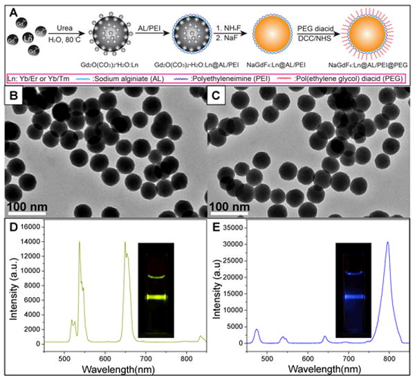
(A) Schematic figure showing the synthesis route of PEGylated β-NaGdF4: Yb/Er and β-NaGdF4: Yb/Tm nanophosphors. (B) TEM image of PEGylated β-NaGdF4: Yb/Er (C) TEM image of PEGylated β-NaGdF4: Yb/Tm nanophosphors. Upconversion luminescence spectra for (D) PEGylated β-NaGdF4:Yb/Er and (E) PEGylated β-NaGdF4:Yb/Tm nanophosphors. The insets show photographs of the luminescence from the respective particle solutions in a 1 cm plastic cuvette during irradiation with a 980 nm laser.
The size of the nanophosphor is continuously tunable from 50 nm to 300 nm by controlling the size of precursor synthesized (Figure S2, supporting information). In order to apply these nanophosphors in bioimaging, amine groups were covalently bonded to PEG by DCC/NHS chemistry.[16] The TEM images shown in Figure 1 indicate the obtained PEGylated upconversion nanophosphors were spherical and monodispersed with mean diameter of 50 +/- 5 nm (the size distribution is shown in Figure S3, supporting information). The AL and PEI coating were shown to be very effective at preventing aggregation. The obtained phosphors without polyelectrolyte coating prior to hydrothermal treatment were irregular microsized crystals (Figure S4, supporting information). The presence of PEG coating was confirmed by zeta potential (-21.0 mV) and FTIR (Figure S5, supporting information).
The upconversion nanophosphors display bright luminescence under 980 nm laser excitation (Figure 1D, E). The main emission peaks of the PEGylated β-NaGdF4:Yb/Er were observed at 537 and 654 nm, which corresponds to the Er3+ transition 4S3/2→4I15/2 and 4F9/2→4I15/2, respectively. The Yb/Tm doped nanophosphors (β-NaGdF4:Yb/Tm) displayed very intense luminescence at 800 nm which was assigned to the 3H4→3H6 transition of Tm3+. These near-infrared exciting and emitting upconversion phosphors are promising for cell labeling and deep tissue imaging applications.
2.2 Synthesis and optical properties of magnetic upconversion nanophosphors
In order to demonstrate the flexibility of this controlled synthesis method, magnetic upconversion nanophosphors were synthesized with a magnetic core and upconversion shell. As illustrated in Figure 2, hydrophobic oleic acid capped Fe3O4 nanoseeds were first treated with NaIO4 to make their surface hydrophilic.[17] The strong oxidizer-NaIO4 breaks the double bond in oleic acid and generates a carboxyl group at the end of the ligand (zeta potential: -23.5 mV). The precursor of the upconversion nanophosphor (Gd2O(CO3)2•H2O:Yb/Er or Yb/Tm) was deposited on the surface of iron oxide nanoparticles sequentially by a modified protocol from literature.[15b, 15d] The rest of the protocol, i.e. polymer coating, NH4F etching, autoclave incubation with NaF, and PEGylation are similar to the previously described single-component upconversion nanoparticle synthesis.
Figure 2.
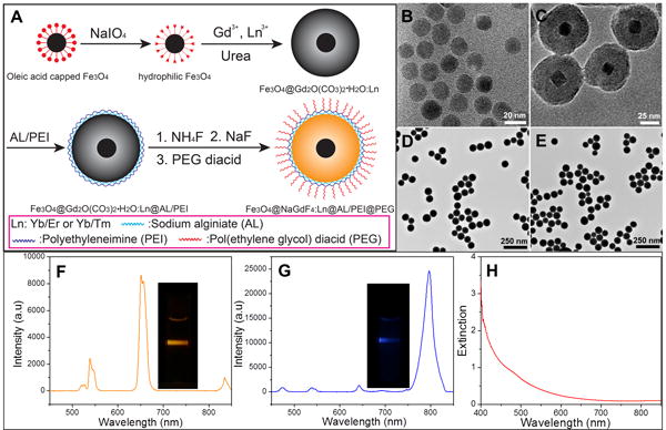
(A) Schematic figure showing the synthesis route of PEGylated Fe3O4@β-NaGdF4: Yb/Er or Yb/Tm nanophosphors. TEM image of (B) Fe3O4 seeds after surface modification, (C) Fe3O4@Gd2O(CO3)2•H2O:Yb/Er@AL/PEI, (D) PEGylated Fe3O4@NaGdF4:Yb/Er, (E) PEGylated Fe3O4@NaGdF4:Yb/Tm. Upconversion luminescent spectra and images for (F) PEGlayted Fe3O4@β-NaGdF4:Yb/Er, (G) PEGlayted Fe3O4@β-NaGdF4:Yb/Tm nanophosphor, (H) Extinction spectrum of a 0.18 mg/mL colloidal solution of oleic acid-coated magnetite cores in a 1 cm path length cuvette.
The TEM image in Figure 2B shows the monodispersed hydrophilic Fe3O4 nanoseeds with mean size of 17.5 +/- 3 nm in diameter after surface modification. The core shell structure of magnetic upconversion phosphor precursor (Fe3O4@Gd2O(CO3)2•H2O:Yb/Er) with an iron oxide core and ∼25 nm upconversion phosphor precursor shell (Gd2O(CO3)2•H2O:Yb/Er) is clearly distinguished in Figure 2C. After the Gd2O(CO3)2•H2O:Yb/Er was converted to β-NaGdF4:Yb/Er and the surface was functionalized with PEG, monodispersed PEGylated Fe3O4@β-NaGdF4:Yb/Er was obtained with an average size of 65 +/- 17 nm.(Figure S6B, supporting information) The interface between Fe3O4 and β-NaGdF4:Yb/Er is not distinguishable in the TEM image due to low contrast between the materials of magnetic core (Fe3O4) and luminescent shell (β-NaGdF4:Yb/Er). The PEGylated Fe3O4@β-NaGdF4:Yb/Tm nanophosphors were synthesized by the same method with an average diameter of 68 +/-18 nm in diameter. (Figure 2E, Figure S6B, supporting information). However, the Fe3O4 core still can be identified from its XRD patterns in Figure S7 (supporting information). Figure S7a and b display the XRD patterns of the Fe3O4 seeds and magnetic luminescent precursor (Fe3O4@Gd2O(CO3)2•H2O:Yb/Er), respectively. After the amorphous Gd2O(CO3)2•H2O:Yb/Er shell was converted to β-NaGdF4:Yb/Er, the XRD patterns corresponding to Fe3O4 core in Figure S7c (Supporting information) are relative weak because the cores have a small volume percentage and cross-section compared to the NaGdF4:Yb/Er. The presence of AL, PEI, and PEG was confirmed by FTIR (Figure S8, Supporting information).
Previous work reported that when the phosphor is in direct contact with the iron oxide, the fluorescence or luminescence will be quenched. The common method to prevent the quenching is to coat a silica or polymer spacer layer (>50 nm thick) between iron oxide and luminescent shell.[12, 18] Even though our magnetic nanophosphors do not have a spacer layer, they still display bright luminescence under 980 nm laser (Figure 2F, G). Compared with the upconversion nanosphors without magnetic component (Figure 1), both the Er3+ and Tm3+ doped magnetic upconversion nanophosphors show a low luminescent quenching effect as a result of the magnetic core. The emission peaks at shorter wavelength are attenuated more than the emission peaks at longer wavelength which is consistent with the extinction spectrum of iron oxide nanocores (Figure 2H).[19]
2.3 Magnetically controlled capture and release of magnetic upconversion nanophosphors
The presence of iron oxide can be clearly observed in the magnetic hysteresis loop of PEGylated Fe3O4@β-NaGdF4:Yb/Er compared with the hysteresis loop of β-NaGdF4:Yb/Er. The room temperature magnetic hysteresis loop of oleic acid capped iron oxide nanoparticles shows the saturation magnetization was 44 emu/g which is lower than reported result (∼84 emu/g)[20] on bulk magnetite due to the large amount (33% w/w, Figure S9, supporting information) of oleic acid absorbed on the surface of iron oxide. The magnetic hysteresis loop of β-NaGdF4:Yb/Er at 300 K indicates the upconversion phosphor is paramagnetic (Figure 3), with a magnetic susceptibility of 1.1×10⁻⁴ emu/g/Oe. After the iron oxide was encapsulated into the paramagnetic β-NaGdF4:Yb/Er, the magnetic hysteresis curve includes a ferrimagnetic component with a saturation magnetization of 7.0 emu/g (64 emu/g normalized by the mass of Fe3O4), a coercivity of 20 Oe, and a magnetic susceptibility (initial slope) of 1.7×10⁻² emu/g/Oe. The saturation magnetization of the magnetic nanophosphors (Fe3O4@β-NaGdF4:Yb/Er) was significantly smaller than the saturation magnetization of bulk magnetite, which is 84 emu/g.[20] The lower measured saturation magnetization can be attributed in large part to the rather small size of the iron oxide nanoparticles[21] and the added mass of the organic ligands and upconversion nanoshell (β-NaGdF4:Yb/Er). Hysteresis is observed in the dry sample because the 17 nm magnetite cores are thermally blocked at room temperature, but in solution the particles will rotate with a Brownian relaxation time of ∼120 μs, and will be superparamagnetic at longer time scales.[22] The aqueous solution of magnetic upconversion nanophosphors can be separated by a magnet within 2 min.
Figure 3.
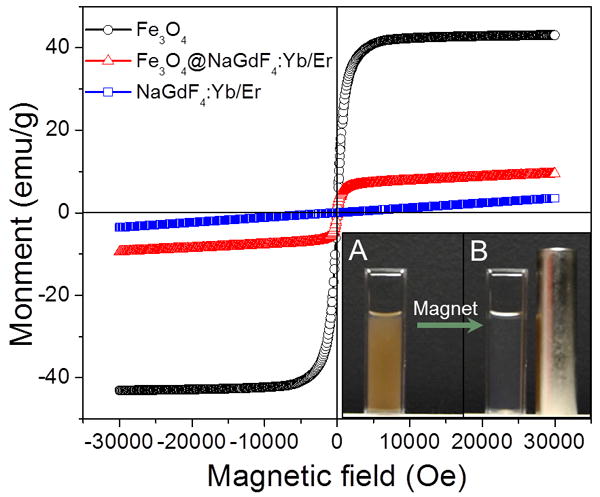
Magnetic hysteresis loop of solid powders of oleic acid capped Fe3O4, PEGylated β-NaGdF4:Yb/Er, Fe3O4, and PEGylated Fe3O4@β-NaGdF4:Yb/Er. Inset figure A shows magnetic upconversion nanoparticles in a 1 cm path length cuvette, while inset figure B shows the clear solution remaining after application of a magnetic field (the cylindrical magnet) for 2 minutes. Note, the brown reflection on the cylindrical magnet is from particles on the right edge of the cuvette.
Magnetic particles can be used as direct drug carriers to local sites in the human body, such as stents,[23] tumors,[24] the inner ear,[25] the retina of the eye,[26] and other regions. The magnetic force on these magnetic particles is given by (in cgs units):
Where is the magnetophoretic force (dyn), is the magnetic moment of the particle (emu), and is the external applied magnetic field (Oe). In solution, the particle magnetic moment aligns with the external field and experiences a force towards the region of highest field, with a force proportional to the gradient.[27] Because the external magnetic field decays roughly with the radius of the magnetic source, there is an inherent tradeoff between magnetic field uniformity and field gradient such that the strongest field gradients occur in close proximity to small magnetic field sources. Implanted magnetic materials such as stents offer a method to generate strong local fields and field gradients to capture particles. Stents are widely used to expand blood vessels in treatment of coronary heart disease, peripheral artery disease, renal artery stenosis, and carotid artery disease but create risk of potentially fatal thrombosis.[28] Drug eluting polymer coatings have been developed to reduce inflammation, but it's difficult to control drug release over long periods and cannot be replenished. Magnetizable stents have been used to capture endothelial cells[29] or drugs such as paclitaxel[23] and sirolimus[30] by magnetic nanoparticles to prevent stent thrombosis[28] and restenosis,[28] relying on external fields to magnetize the stents in order to create large field gradients. Alternatively, to capture particles in the absence of an external field, permanent magnetic materials may be used such as duplex steel.[29] For all these applications, it is important to have magnetic carriers that can be controlled and imaged in order to study accumulation and release. We show here that our particles can be captured via a permanently magnetized film, and that the particles can be released after capture using an external magnetic field.
Figure 4 shows the principle of magnetic upconversion nanophosphors capture and release by a film of permanent magnetic materials. The magnetic film is a refridgerator magnet with an adhesive backing (McMasterCarr, Inc., Atlanta, GA) which is composed of an array of alternating magnetic regions 1 mm wide (Figure 4A); this geometry is designed to generate strong field gradients over small distances in order to attach strongly to the iron in refrigerator doors. The magnetic field gradients are strong enough to capture upconversion nanophosphors from a flowing solution of nanophosphors in PBS (Figure 4B). The captured magnetic upconversion nanophosphors can be imaged under 980 nm light, during capture and holding (Figure 4C). In order to release the particles, an external magnetic field is applied in order to rearrange the particles into chains aligned with this field. The formation of chains pushes the particles into the fluid, where they are carried by the flow in the tube (Figure 4D). The flow velocity near the surface to be essentially static, but increases quadratically towards the center of the tube. Permanent magnetic arrays materials have been used to assemble magnetic particle arrays,[31] to transport them across a magnetic array surface in rotating magnetic fields,[32] and to push magnetic fluids into the inner ear.[25, 33] To our knowledge, however, this is the first report of nanoparticle capture and release from a permanent magnetic structure. Compared to conventional approaches of capturing particles with soft magnetic materials by applying a field and release by removing the field, the advantage of our approach is that for biomedical applications, capture often occurs over long periods where application of a magnetic field is inconvenient, and release is often desired to be rapid and controlled.
Figure 4.
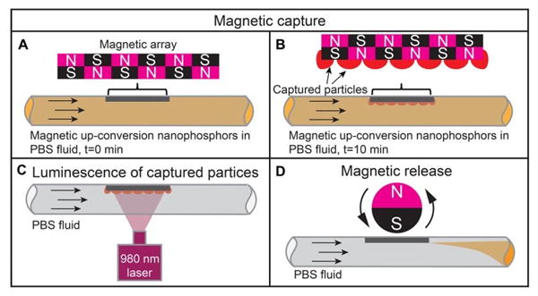
Schematic showing the magnetic capture and release of mangetic upconversion nanophosphors.
Figure 5 A and B shows a photograph of the magnetic upconversion nanophosphors during captured from a 1 mg/mL solution in PBS fluid with a flow rate of 0.5 mL/s in a 5 mm inner diameter tube. The captured particles form a dashed-line pattern when they are attracted to the high field gradient regions between the alternating magnetic domains in the fridge magnet (Figure 5B and C). The pattern of particles is most clearly observed under 980 nm irradiation (Figure 5E). This bright upconversion luminescence can be used to track the particles in deep tissue due to the near infrared emission. After applying a rotating external magnetic field, the magnetic upconversion nanophosphors are released into the fluid (Figure 5D and F). This is significant because it shows that particles can be captured and retained on magnetized surfaces for long periods, and subsequently released using external magnetic fields. Future work will investigate the amount released as a function of external field strength, pulse duration, and flow rate. We will also functionalize particles with anti-inflammatory and antimicrobial drugs.
Figure 5.
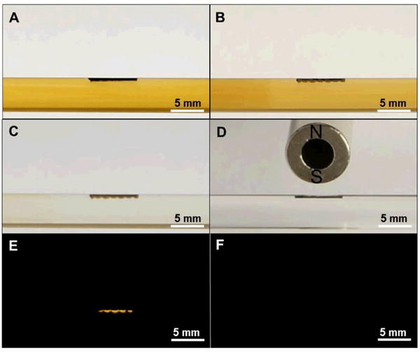
Photographs of (A) magnetic upconversion nanophosphors solution in a glass tube with a magnetic film in the tube (black rectangle) at t=0 min, (B) magnetic upconversion nanophosphors fluid with captured in an array pattern the magnetic film (t=10 min), (C) captured magnetic upconversion nanophosphors held on magnetic film during rinsing PBS soluton, (D) magnetic film after the magnetic upconversion nanophosphors were released by the external field, (E) Upconversion luminescence of captured magnetic upconversion nanophosphors on magnetic film during rinsing with PBS solution (the size of luminescent area depends on the beam size of the 980 nm laser), (F) Upconversion luminescence of magnetic film after magnetic upconversion phosphors were released by external magnetic field.
2.4 In vitro cytotoxicity test and bio-imaging by upconversion nanophosphors
To test whether the synthesized upconversion nanophosphors would be endocytosed by cells, we incubated MCF-7 breast cancer cells with PEGylated magnetic upconversion phosphors (Fe3O4@β-NaGdF4:Yb/Er, 250 μg/ml) for 24 hrs. The MCF-7 breast cancer cells were then washed six times to eliminate nanocapsules from the cell culture media. As shown in Figure 6, the cells incubated with magnetic nanophosphors became brightly luminescent under 980 nm excitation, while there was no observed luminescence from the unlabeled control sample.
Figure 6.
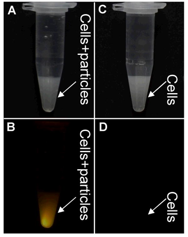
Photographs of MCF-7 breast cancer cell suspensions in 1.5 mL centrifuge tubes. Cells incubated with PEGylated Fe3O4@β-NaGdF4:Yb/Er were viewed either under room light (A) or 980 nm irradiation (B). Control cells without incubation with PEGylated Fe3O4@β-NaGdF4:Yb/Er, were viewed either under room light (C) or 980 nm irradiation (D).
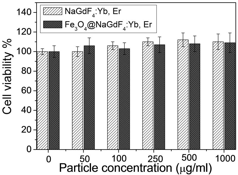
In order to study the potential cytotoxicity of the magnetic upconversion nanophosphors, an in vitro cytotoxicity test of magnetic upconversion nanophosphors was performed on MCF-7 breast cancer cells (Figure 7). The viability of the untreated cells was set as 100% to calculate the viability of the cells treated by different concentration of upconversion nanophosphors. Cell viability is not significantly affected by the magnetic upconversion nanophosphor up to concentration of at least 1000 μg/ml.
Figure 7.
Cytotoxicity study of PEGylated β-NaGdF4:Yb/Er and PEGylated Fe3O4@β-NaGdF4:Yb/Er.
Rare earth elements are toxic in their free ionic form.[34] For example, gadolinium MRI contrast agents can reduce neuromuscular transmission and interfere with cell membranes and intracellular enzymes because Gd3+ can prevent the transportation of calcium through ion channels of muscle cells and nerve tissue cells if the chelator is not sufficiently stable.[35] To test the chemical stability of the magnetic upconversion Fe3O4@β-NaGdF4:Yb/Er particles, we incubated a solution of particles (1 mg/ml) in nitrate acid (0.5 M) at 37 °C for 24 hr. ICP tests for free Gd3+ and Fe3+ showed no detectable dissolution of magnetic core and luminescent shell (Fe <0.1 ppm, Gd<0.1 ppm), while in a control with a mixture of hydrophilic Fe3O4 nanoparticles and β-NaGdF4:Yb/Er nanoparticles, the Fe3O4 nanoparticles completely dissolved. These results indicate that upconversion phosphors (β-NaYF4:Yb/Er) are highly chemically stable and prevent dissolution of magnetic core in acid environments (e.g. lysosomes and endosomes). The intense luminescent signal and chemical stability of magnetic nanophosphors is useful in cell labeling and magnetic guidance targeting.
2.5 Deep tissue and MRI imaging of magnetic nanophosphors
To demonstrate the feasibility of the magnetic nanophosphors for imaging through deep tissue (e.g. for locating tumors), PEGylated Fe3O4@β-NaGdF4:Yb/Tm nanophosphors with near infrared emission at 800 nm were injected into chicken breast. These magnetic nanophosphors display extremely bright luminescence without background signal under 1 cm thickness of chicken breast at a dose of 1 mg/ml (200 μl), see Figure 8.
Figure 8.
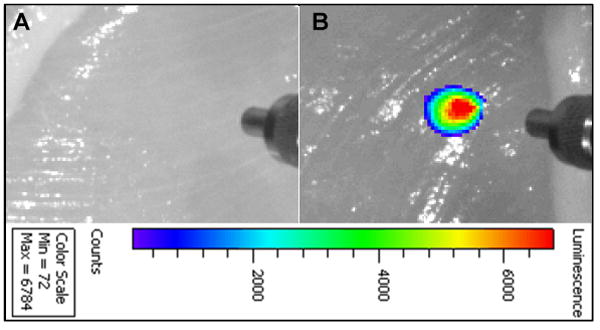
Deep tissue imaging of magnetic upconversion nanophosphors after 200 μl of (A) PBS solution and (B) 1 mg/ ml PEGylated Fe3O4@β-NaGdF4:Yb/Tm were injected into chicken breast at 1 cm depth. The concentric cylindrical object at the right of each image is an SMA905 terminus of an optical fiber used to illuminate the tissue with 980 nm light. The black and white chicken breast image was acquired under overhead illumination, and the pseudo-colored upconversion luminescence image was superimposed.
The magnetic upconversion nanophosphors may also potentially serve as T1 and T2-weighted MRI contrast agents due to the single domain ferrimagnetic Fe3O4 core and paramagnetic shell (β-NaGdF4). In order to measure their relaxivity, different concentrations of Fe3O4@β-NaGdF4:Yb/Tm nanophosphors were prepared in 1 wt% agarose gel and imaged with a 4.7 T MRI instrument. Figure 9 clearly shows the positive T1 and negative T2 contrast effects of the magnetic nanophosphors: the T1-weighted images become brighter with increased particle concentration, while the T2-weighted images become darker with increased particle concentration. The T1 relaxivity coefficient (r1) for the magnetic nanophosphor (Fe3O4@β-NaGdF4:Yb/Tm) could also be calculated from the curve of 1/T1 vs. concentration of gadolinium (Figure 9A). The data shows that r1 is 2.9 mM-1 s-1 which is similar to the relaxivity (2.8 mM-1 s-1) reported on NaGdF4:Yb/Er[36]. However, the calculated r2 is as high as 204 mM-1 s-1 which is much larger than FDA-approved iron oxide nanoparticle contrast agents such as Ferumoxtran (Resovist®, 65 mM-1 s-1), cross-linked iron oxide particle (CLIO-Tat, 62 mM-1 s-1), and water soluble iron oxide (WSIO, 78 mM-1s-1).[37]
Figure 9.
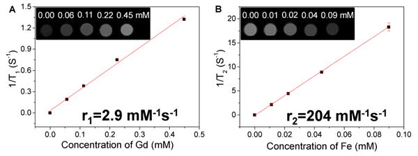
T1 and T2-weighted MRI images and relativities for PEGylated magnetic upconversion nanophosphors (Fe3O4@β-NaGdF4:Yb/Er).
3. Conclusion
We successfully developed a novel method to synthesize PEGylated upconversion nanophosphors with controlled monodispersed sizes, and prevented aggregation via polyelectrolye coating of the precursors. The approach is versatile and was used to prepare PEGylated magnetic upconversion nanophosphors with an iron oxide core and a luminescent shell of uniform thickness. We expect that such bifunctional nanocomposites, combining the advantages of magnetism and luminescence, will find extensive applications in magnetic delivery and MRI/luminescence bioimaging. Future work will focus on the magnetic field guided in vivo tumor targeting and stent functionalization.
Supplementary Material
Acknowledgments
This research was supported in part by NIH award 1R15EB014560 to HC and JNA, an NSF award CMMI-1100684 to BQ and OTM, and an NSF award CMMI-1130636 to TC. Electron microscopy images were acquired at the Clemson University Electron Microscope Facility and use of this facility was funded by The Center of Biomaterials for Tissue Regeneration (CBTR) funded under NIH grants 5P20RR021949 and 8P20GM103444.
Footnotes
Supporting Information: Supporting Information, comprising the experimental methods, and characterization data via X-ray diffraction, electron microscopy images, FTIR spectroscopy, and thermogravimetric analysis, is available from the Wiley Online Library or from the author.
References
- 1.a) Mader HS, Kele P, Saleh SM, Wolfbeis OS. Current Opinion in Chemical Biology. 2010;14:582. doi: 10.1016/j.cbpa.2010.08.014. [DOI] [PubMed] [Google Scholar]; b) Zhou J, Liu Z, Li F. Chemical Society Reviews. 2012;41 doi: 10.1039/c1cs15187h. [DOI] [PubMed] [Google Scholar]; c) Wang F, Banerjee D, Liu Y, Chen X, Liu X. Analyst. 2010;135:1839. doi: 10.1039/c0an00144a. [DOI] [PubMed] [Google Scholar]
- 2.Soukka T, Rantanen T, Kuningas K. Annals of the New York Academy of Sciences. 2008;1130:188. doi: 10.1196/annals.1430.027. [DOI] [PubMed] [Google Scholar]
- 3.Achatz D, Ali R, Wolfbeis O. In: Luminescent Chemical Sensing, Biosensing, and Screening Using Upconverting Nanoparticles. Prodi L, Montalti M, Zaccheroni N, editors. Vol. 300. Springer Berlin Heidelberg; 2011. p. 29. [DOI] [PubMed] [Google Scholar]
- 4.Wang F, Liu X. Chemical Society Reviews. 2009;38:976. doi: 10.1039/b809132n. [DOI] [PubMed] [Google Scholar]
- 5.a) Wang L, Li Y. Chemistry of Materials. 2007;19:727. [Google Scholar]; b) Li Z, Zhang Y. Nanotechnology. 2008;19:345606. doi: 10.1088/0957-4484/19/34/345606. [DOI] [PubMed] [Google Scholar]
- 6.a) Mai HX, Zhang YW, Si R, Yan ZG, Sun Ld, You LP, Yan CH. Journal of the American Chemical Society. 2006;128:6426. doi: 10.1021/ja060212h. [DOI] [PubMed] [Google Scholar]; b) Teng X, Zhu Y, Wei W, Wang S, Huang J, Naccache R, Hu W, Tok AIY, Han Y, Zhang Q, Fan Q, Huang W, Capobianco JA, Huang L. Journal of the American Chemical Society. 2012;134:8340. doi: 10.1021/ja3016236. [DOI] [PubMed] [Google Scholar]
- 7.a) Yi GS, Chow GM. Advanced Functional Materials. 2006;16:2324. [Google Scholar]; b) Chen G, Ohulchanskyy TY, Kumar R, Ågren H, Prasad PN. ACS Nano. 2010;4:3163. doi: 10.1021/nn100457j. [DOI] [PMC free article] [PubMed] [Google Scholar]
- 8.a) Hu FQ, Wei L, Zhou Z, Ran YL, Li Z, Gao MY. Advanced Materials. 2006;18:2553. [Google Scholar]; b) Chen FH, Zhang LM, Chen QT, Zhang Y, Zhang ZJ. Chemical Communications. 2010;46:8633. doi: 10.1039/c0cc02577a. [DOI] [PubMed] [Google Scholar]; c) Yu MK, Jeong YY, Park J, Park S, Kim JW, Min JJ, Kim K, Jon S. Angewandte Chemie International Edition. 2008;47:5362. doi: 10.1002/anie.200800857. [DOI] [PubMed] [Google Scholar]; d) Jun Yw, Huh YM, Choi Js, Lee JH, Song HT, KimKim, Yoon S, Kim KS, Shin JS, Suh JS, Cheon J. Journal of the American Chemical Society. 2005;127:5732. doi: 10.1021/ja0422155. [DOI] [PubMed] [Google Scholar]; e) Katagiri K, Imai Y, Koumoto K, Kaiden T, Kono K, Aoshima S. Small. 2011;7:1683. doi: 10.1002/smll.201002180. [DOI] [PubMed] [Google Scholar]; f) Guardia P, Di Corato R, Lartigue L, Wilhelm C, Espinosa A, Garcia-Hernandez M, Gazeau F, Manna L, Pellegrino T. ACS Nano. 2012;6:3080. doi: 10.1021/nn2048137. [DOI] [PubMed] [Google Scholar]
- 9.Shen J, Sun LD, Zhang YW, Yan CH. Chemical Communications. 2010;46:5731. doi: 10.1039/c0cc00814a. [DOI] [PubMed] [Google Scholar]
- 10.Zhang F, Braun GB, Pallaoro A, Zhang Y, Shi Y, Cui D, Moskovits M, Zhao D, Stucky GD. Nano Letters. 2011;12:61. doi: 10.1021/nl202949y. [DOI] [PubMed] [Google Scholar]
- 11.He M, Huang P, Zhang C, Hu H, Bao C, Gao G, He R, Cui D. Advanced Functional Materials. 2011;21:4470. [Google Scholar]
- 12.Gai S, Yang P, Li C, Wang W, Dai Y, Niu N, Lin J. Advanced Functional Materials. 2010;20:1166. [Google Scholar]
- 13.Zhong C, Yang P, Li X, Li C, Wang D, Gai S, Lin J. RSC Advances. 2012;2:3194. [Google Scholar]
- 14.Yoo JW, Chambers E, Mitragotri S. Current pharmaceutical design. 2010;16:2298. doi: 10.2174/138161210791920496. [DOI] [PubMed] [Google Scholar]
- 15.a) Ahrén M, Selegård La, Klasson A, Söderlind F, Abrikossova N, Skoglund C, Bengtsson Tr, Engström M, Käll PO, Uvdal K. Langmuir. 2010;26:5753. doi: 10.1021/la903566y. [DOI] [PubMed] [Google Scholar]; b) Chen H, Colvin DC, Qi B, Moore T, He J, Mefford OT, Alexis F, Gore JC, Anker JN. Journal of Materials Chemistry. 2012;22:12802. doi: 10.1039/C2JM15444G. [DOI] [PMC free article] [PubMed] [Google Scholar]; c) Petoral RM, Söderlind F, Klasson A, Suska A, Fortin MA, Abrikossova N, Selegård La, Käll PO, Engström M, Uvdal K. The Journal of Physical Chemistry C. 2009;113:6913. [Google Scholar]; d) Chen H, Moore T, Qi B, Colvin DC, Jelen EK, Hitchcock DA, He J, Mefford OT, Gore JC, Alexis F, Anker JN. ACS Nano. 2013 doi: 10.1021/nn304369m. [DOI] [PMC free article] [PubMed] [Google Scholar]
- 16.Chul Cho K, Hoon Jeong J, Jung Chung H, Joe CO, Wan Kim S, Gwan Park T. Journal of Controlled Release. 2005;108:121. doi: 10.1016/j.jconrel.2005.07.015. [DOI] [PubMed] [Google Scholar]
- 17.Wang M, Peng M, Cheng W, Cui Y, Chen C. Journal of Nanoscience and Nanotechnology. 2011;11:3688. doi: 10.1166/jnn.2011.3751. [DOI] [PubMed] [Google Scholar]
- 18.Yu X, Shan Y, Li G, Chen K. Journal of Materials Chemistry. 2011;21:8104. [Google Scholar]
- 19.a) Schlegel A, Alvarado SF, Wachter P. Journal of Physics C: Solid State Physics. 1979;12:1157. [Google Scholar]; b) Tang J, Myers M, Bosnick KA, Brus LE. The Journal of Physical Chemistry B. 2003;107:7501. [Google Scholar]
- 20.O'handley RC. Modern magnetic materials: principles and applications. Wiley New York: 2000. [Google Scholar]
- 21.Goya GF, Berquo TS, Fonseca FC, Morales MP. Journal of Applied Physics. 2003;94:3520. [Google Scholar]
- 22.Rosensweig RE. Journal of Magnetism and Magnetic Materials. 2002;252:370. [Google Scholar]
- 23.Chorny M, Fishbein I, Yellen BB, Alferiev IS, Bakay M, Ganta S, Adamo R, Amiji M, Friedman G, Levy RJ. Proceedings of the National Academy of Sciences. 2010;107:8346. doi: 10.1073/pnas.0909506107. [DOI] [PMC free article] [PubMed] [Google Scholar]
- 24.Fortin-Ripoche JP, Martina MS, Gazeau F, Ménager C, Wilhelm C, Bacri JC, Lesieur S, Clément O. Radiology. 2006;239:415. doi: 10.1148/radiol.2392042110. [DOI] [PubMed] [Google Scholar]
- 25.Sarwar A, Lee R, Depireux DA, Shapiro B. Magnetics, IEEE Transactions on. 2013;49:440. [Google Scholar]
- 26.Yanai A, feli UO, Metcalfe AL, Soema P, Addo L, Gregory-Evans CY, Po K, Shan X, Moritz OL, Gregory-Evans K. Cell Transplantation. 2012;21:1137. doi: 10.3727/096368911X627435. [DOI] [PubMed] [Google Scholar]
- 27.Cherry EM, Maxim PG, Eaton JK. Medical Physics. 2010;37:175. doi: 10.1118/1.3271344. [DOI] [PubMed] [Google Scholar]
- 28.Kempe H, Kempe M. Biomaterials. 2010;31:9499. doi: 10.1016/j.biomaterials.2010.07.107. [DOI] [PubMed] [Google Scholar]
- 29.Tefft BJ, Gooden JY, Uthamaraj S, Harburn JJ, Klabusay M, Holmes DR, Simari RD, Dragomir-Daescu D, Sandhu GS. Magnetics, IEEE Transactions on. 2013;49:463. [Google Scholar]
- 30.Chong PH, Cheng JW. The Annals of Pharmacotherapy. 2004;38:661. doi: 10.1345/aph.1D256. [DOI] [PubMed] [Google Scholar]
- 31.Yellen B, Friedman G, Feinerman A. Journal of Applied Physics. 2003;93:7331. [Google Scholar]
- 32.Yellen BB, Erb RM, Son HS, Hewlin JR, Shang H, Lee GU. Lab on a Chip. 2007;7:1681. doi: 10.1039/b713547e. [DOI] [PubMed] [Google Scholar]
- 33.Guzzella L, Colaneri P, Banaszuk A. IEEE Control Systems Magazine. 2012 [Google Scholar]
- 34.a) Arsenault TM, King BF, Marsh JW, Goodman JA, Weaver AL, Wood CP, Ehman RL. Mayo Clinic Proceedings. 1996:1150. doi: 10.4065/71.12.1150. [DOI] [PubMed] [Google Scholar]; b) Spencer AJ, Wilson SA, Batchelor J, Reid A, Pees J, Harpur E. Toxicologic pathology. 1997;25:245. doi: 10.1177/019262339702500301. [DOI] [PubMed] [Google Scholar]
- 35.Perazella MA. Current drug safety. 2008;3:67. doi: 10.2174/157488608783333989. [DOI] [PubMed] [Google Scholar]
- 36.Johnson NJJ, Oakden W, Stanisz GJ, Scott Prosser R, van Veggel FCJM. Chemistry of Materials. 2011;23:3714. [Google Scholar]
- 37.a) Wang Y, Hussain S, Krestin G. European radiology. 2001;11:2319. doi: 10.1007/s003300100908. [DOI] [PubMed] [Google Scholar]; b) Josephson L, Tung C, Moore A, Weissleder R. Bioconjugate Chemistry. 1999;10:186. doi: 10.1021/bc980125h. [DOI] [PubMed] [Google Scholar]; c) Jun Y, Huh Y, Choi J, Lee J, Song H, Kim K, Yoon S, Kim K, Shin J, Suh J, Cheon J. Journal of the American Chemical Society. 2005;127:5732. doi: 10.1021/ja0422155. [DOI] [PubMed] [Google Scholar]
- 38.Park J, An K, Hwang Y, Park JG, Noh HJ, Kim JY, Park JH, Hwang NM, Hyeon T. Nat Mater. 2004;3:891. doi: 10.1038/nmat1251. [DOI] [PubMed] [Google Scholar]
Associated Data
This section collects any data citations, data availability statements, or supplementary materials included in this article.


