Abstract

The recently synthesized and isolated low-coordinate FeV nitride complex has numerous implications as a model for high-oxidation states in biological and industrial systems. The trigonal [PhB(tBuIm)3FeV≡N]+ (where (PhB(tBuIm)3– = phenyltris(3-tert-butylimidazol-2-ylidene)), (1) low-spin d3 (S = 1/2) coordination compound is subject to a Jahn–Teller (JT) distortion of its doubly degenerate 2E ground state. The electronic structure of this complex is analyzed by a combination of extended versions of the formal two-orbital pseudo Jahn–Teller (PJT) treatment and of quantum chemical computations of the PJT effect. The formal treatment is extended to incorporate mixing of the two e orbital doublets (30%) that results from a lowering of the idealized molecular symmetry from D3h to C3v through strong “doming” of the Fe–C3 core. Correspondingly we introduce novel DFT/CASSCF computational methods in the computation of electronic structure, which reveal a quadratic JT distortion and significant e–e mixing, thus reaching a new level of synergism between computational and formal treatments. Hyperfine and quadrupole tensors are obtained by pulsed 35 GHz ENDOR measurements for the 14/15N-nitride and the 11B axial ligands, and spectra are obtained from the imidazole-2-ylidene 13C atoms that are not bound to Fe. Analysis of the nitride ENDOR tensors surprisingly reveals an essentially spherical nitride trianion bound to Fe, with negative spin density and minimal charge density anisotropy. The four-coordinate 11B, as expected, exhibits negligible bonding to Fe. A detailed analysis of the frontier orbitals provided by the electronic structure calculations provides insight into the reactivity of 1: JT-induced symmetry lowering provides an orbital selection mechanism for proton or H atom transfer reactivity.
Introduction
The reaction mechanism of nitrogen “fixation” by nitrogenase enzymes, involving cleavage of the very strong and nonpolar N≡N bond to generate two NH3 molecules under ambient conditions, has been a topic of intense interest for many decades.1,2 Inspired by the structure of the nitrogenase active-site metallocluster, the iron–molybdenum cofactor (FeMo-co), this has led to a strong interest in the synthesis and characterization of transition-metal complexes of Fe and Mo that bind N2 and intermediates of N2 reduction and can even catalyze the production of NH3.3,4 The trigonal Schrock Mo complex5 [HIPTN3N]Mo(N2) = [(3,5-(2,4,6-iPr3C6H2)2C6H3NCH2CH2)3N]Mo(N2) (2) catalyzes N2 reduction by a “distal” pathway6 in which three hydrogenations at a single N of bound N2, followed by N–N bond cleavage, generates one molecule of NH3 along with a terminal metal nitride [M≡N]; three subsequent hydrogenations then form the second NH3 molecule. The appearance of a metal nitride in one proposed mechanism for nitrogen fixation by nitrogenase links these synthetic efforts to investigations of the Haber–Bosch process for nitrogen fixation, which celebrated its centenary as an industrial process last year and which utilizes an Fe catalyst whose mechanism has been shown to involve iron nitride intermediates.7 Peters and co-workers have recently synthesized two similar trigonal tris-triphosphino FeI complexes that likewise catalyze N2 reduction, but characterization of their reaction pathways is not yet completed.8
Recently an FeV≡N complex, [PhB(tBuIm)3FeV≡N]+ (where PhB(tBuIm)3– = phenyltris(3-tert-butylimidazol-2-ylidene)), has been shown to generate high yields of ammonia under very mild conditions, using water as the proton source.9 In contrast to 4-fold symmetry, where some transient FeV≡N complexes10,11 have been spectroscopically characterized, ligands that enforce three-fold symmetry allow for the isolation of four-coordinate, diamagnetic FeIV≡N complexes12−17 as well as this paramagnetic species, the first FeV≡N complex (1, Figure 1) to be isolated and which has relevance to possible intermediates in nitrogen fixation.9 This FeV≡N complex serves as a spectroscopic marker for the possible nitride intermediate of the proposed “distal” pathway of nitrogen fixation by nitrogenase as well as serving as a model for the established intermediate of the Haber–Bosch process.
Figure 1.
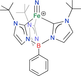
FeV nitride, 1. [PhB(tBuIm)3FeV≡N]+ ((PhB(tBuIm)3– = phenyltris(3-tert-butylimidazol-2-ylidene)).
Beyond these connections to nitrogen fixation, compound 1 is of intrinsic interest. The d3, FeV center of 1 has an idealized trigonal pyramidal geometry and is therefore susceptible to a Jahn–Teller (JT) distortion as observed in other d3S = 1/2 metal centers with idealized C3v symmetry.18,19 The 35 K X-ray crystal structure shows that 1 does exhibit the expected deviations from the idealized C3v symmetry, with a B–Fe≡N angle of 173.6°. Correspondingly, Scepaniak et al.9 showed by DFT computations that the degenerate 2E ground state is slightly split, resulting in a corresponding splitting of the low-lying d(x2–y2) and d(xy) Fe d orbitals. Beyond this, the trigonal ligand field generated by the tridentate ligand creates a d orbital pattern that plays a significant role in stabilizing a low spin state of the FeV center.20
In view of the relevance of 1 to intermediates in catalytic nitrogen fixation and its intrinsic importance in understanding the electronic and vibronic structure of such JT-active, orbitally degenerate states, as enhanced by previous reports that indicate unusual bonding interactions in four-coordinate iron nitride complexes, we have investigated the electronic structure of 1 by EPR and ENDOR spectroscopies in combination with detailed electronic structure calculations. Interpretation of the g tensor of 1 has been made within the context of a first-order “pseudo Jahn–Teller” (PJT) formalism that treats the vibronic JT effect in parallel with spin-orbit coupling (SOC). However, this complex possesses an extremely strong vibronic coupling, much stronger than the SOC, that severely warps the ground state adiabatic potential energy surface (APES), and is reflected in the low-symmetry distortion (C3v → Cs) that is observed crystallographically. A key element in the large JT distortion is strong mixing of the d(xz)/d(yz) and d(x2 – y2)/d(xy) orbital doublets (e–e mixing) that occurs because the idealized symmetry of this trigonal complex is not D3h, which exhibits pure doublets, but is lowered to ∼C3v. This phenomenon is central to the analysis of the PJT effect, and both are included for the first time in the formal treatment and are analyzed in detail with DFT computations. Analyses of the 14N quadrupole and hyperfine couplings of the nitride ligand in 1 support a surprising picture in which the FeV ion binds an essentially spherically symmetric nitride trianion.
Materials and Methods
Sample Preparation
The [PhB(tBuIm)3FeV≡N]BArF24 (PhB(tBuIm)3– = phenyltris(3-tert-butylimidazol-2-ylidene; BArF24 = B(3,5-(CF3)2C6H3)4–) complex was prepared as described previously.9 A 50% 15N enrichment of the nitride of the FeIV precursor complex was accomplished using Na15N=N=N as the nitrogen atom source. Each 14/15N product was chemically oxidized, decanted, washed, and dried as previously described.9 The final desired product was dissolved in the desired amount of 2-methyltetrahydrofuran in custom quartz EPR tubes and frozen at 77 K under a N2 atmosphere.
EPR and ENDOR
Q-band (∼35 GHz) ESE-EPR and ENDOR spectra were collected at 2 K on custom-built instruments previously described.21−23 Pulsed ENDOR experiments employed either the Mims (π/2 – τ – π/2 – T – π/2 – τ – echo) or the Davies (π – T – π/2 – τ – π – τ – echo) microwave pulse sequence, in which the rf pulse is applied during time period T.24 All pulse experiment data acquisition was performed with the SpecMan software package25 (http://specman4epr.com) in conjunction with a Spin-Core PulseBlaster ESR_PRO 400 MHz word generator and Agilent Technologies Acquiris DP235 500MS/sec digitizer.
The ENDOR spectrum for a single molecular orientation from a nucleus with spin of I = 1/2 (13C, 15N) and from the ms = ± 1/2 electron-spin manifold exhibits a doublet at frequencies:
| 1 |
where vn is the nuclear Larmor frequency and A is the orientation-dependent hyperfine coupling. When I ≥ 1 (11B, 14N), an first-order orientation-dependent nuclear quadrupole interaction (P) introduces further splitting of the v± ENDOR lines into manifolds, each with 2I peaks, at frequencies:
| 2 |
for the transition, mI ↔ mI – 1 when P ≪ |vI ± A/2|. Procedures for determining hyperfine and quadrupole tensors through analysis of the 2D field-frequency pattern of ENDOR spectra collected at multiple fields across the EPR envelope are well established.26−29 EPR and ENDOR simulations were performed in Matlab with the easyspin (v4.5) toolbox.30
Absolute hyperfine coupling signs were determined with the Pulsed ENDOR SaTuration and REcovery (PESTRE) protocol.31−33 This protocol determines the sign of A/gn by the application of multiple Davies ENDOR sequences in three stages. The first stage, without rf, saturates the EPR signal and establishes the baseline (BSL). In the second stage, the ENDOR response is saturated by the application of a single rf frequency applied during multiple Davies pulse sequences. The responses of the third stage, again without rf, generate a time varying “dynamic reference level” (DRL), which relaxes back to the BSL. The sign of A is determined by the sign of the difference between the DRL and BSL, termed the DRLδ. When examining the v+ branch of a nucleus with gn > 0, such as 14N, a positive DRLδ implies, A < 0, a negative DRLδ implies, A > 0; for a nucleus with gn < 0, such as 15N, the opposite is true.
Computational Methods
DFT symmetry constrained (C3v) and fully relaxed geometry optimizations, relaxed surface scans, time-dependent density functional theory (TD-DFT), and single-point two-component spin-orbit DFT (SO-DFT) calculations were performed using the ADF2012.01 code.34 ADF DFT calculations used a triple-ζ STO basis (TZP) and the ZORA scalar relativistic Hamiltonian was used for calculations that did not employ spin-orbit coupling. Two-component spin-orbit single-point energy calculations were performed on the high-symmetry (C3v) DFT-optimized geometry. DFT-derived EPR parameters were calculated with ORCA 2.9.135−43 using the def2-TZVP basis and the PBE0 functional.
CASSCF/NEVPT2 (def2-SVP basis for light atoms and def2-TZVP for Fe) calculations were performed using ORCA 2.9.138 The initial guess orbitals were the quasi-restricted orbitals (QROs) taken from a single-point DFT (ORCA 2.9.1, PBE0, def2-TZVP) calculation on the previously DFT-optimized structure (ADF). The CAS(9,8) active space was constructed from selected orbitals containing majority Fe and/or nitride character. The ground-state specific CASSCF calculation was performed in order to gain insight into the electronic origin of experimental hyperfine coupling parameters, spin polarization and delocalization effects, and to compare spin densities with those obtained from DFT calculations. Quasi-degnerate perturbation theory (QDPT) SOC42,44 calculations for the determination of the molecular g tensor were performed using a 20-state CASSCF/NEVPT2 calculation, averaging over the first 5 roots (states of large ligand field character).
Results and Analysis
EPR and Electronic Origin of g Tensor Anisotropy
The 2 K Q-band ESE-EPR spectrum of 1 exhibits axial symmetry with g∥ = 2.30 assigned to the direction of the Fe≡N bond and g⊥ = 1.98 to the Fe-tripodal unit. Simulation of this spectrum gives a substantially greater line width at g∥ than g⊥ (Figure 2), as reported previously.9 These g values are characteristic of a d3 FeV, S = 1/2 ion with a doubly degenerate ground state, 2E, that in the idealized C3v symmetry is subject to a Jahn–Teller (JT) distortion.45,46
Figure 2.
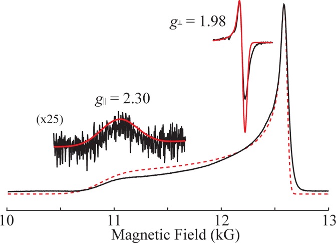
“Q-band” absorption-like ESE-EPR spectra of 50% 15N labeled FeV nitride complex in frozen 2-methyltetrahydrofuran is shown in black with respective simulation in red. Simulations of an axial g, g∥ = 2.30 and g⊥ = 1.98, with EPR line widths (measured at fwhm) of 460 and 50 G, respectively, matches the observed EPR spectrum. Insets are of the numerical derivative of observed spectrum, black, and the scaled simulations of each axial feature, red. Conditions: Hahn echo; 2 K; microwave freq, 34.975 GHz; 20 ms repetition time; τ, 500 ns; scan time, 500 s.
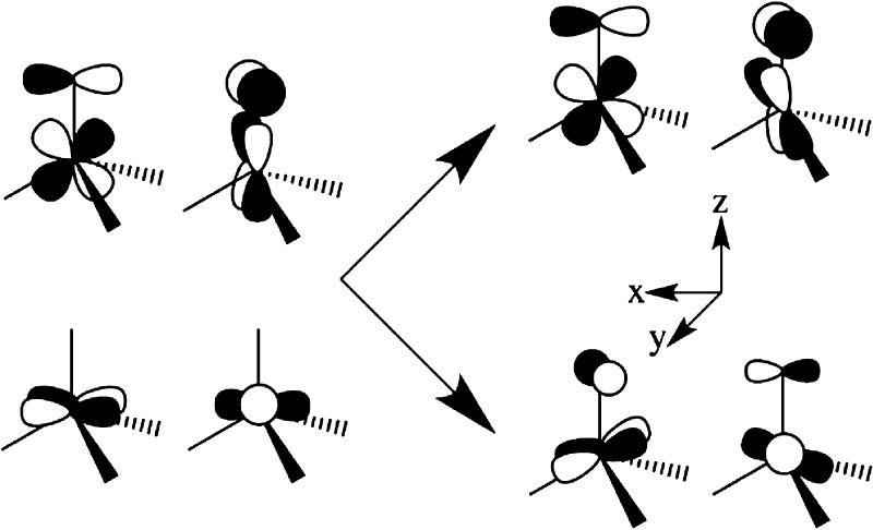
The five d orbitals in D3h symmetry are split into two degenerate e orbital pairs and a single nondegenerate a orbital, typically with ligand field energies in the order d(z2) (a; ml = 0) > [d(x2–y2),d(xy)] (ea;ml = ± 2) > [d(xz),d(yz)] (eb; ml = ± 1), Scheme 1, left. However, in the presence of the strong-field electron-donating nitride/carbene ligands the order of the two e orbital doublets is reversed, leading to the ligand-field ordering indicated in Scheme 1, right.15
Scheme 1.

As a result, an idealized FeV (d3) ion of D3h symmetry would exhibit an orbitally degenerate 2E′ ground state with an [ea]3 electronic configuration that is subject to a JT distortion by vibronic coupling to doubly degenerate ea vibrations.45,46 Linear vibronic coupling replaces the 2E′ electronic degeneracy with a vibronic degeneracy in which the complex is dynamically distorted (e.g., equilateral ↔ isosceles triangle of in-plane C atoms), with the direction of the distortion “pseudorotating” around the symmetry axis. In addition, the low-spin d3 configuration of a trigonally symmetric FeV complex exhibits unquenched orbital angular momentum. As a result SOC competes with the JT distortion along the interaction mode coordinate. The SOC can quench the vibronic distortion, but typically only diminishes it, leading to a situation denoted as the PJT effect, in which the ground adiabatic potential energy surface (APES) takes the shape well-known as the “modified Mexican hat”, Figure 3a.45,46 Incorporation of quadratic terms in the vibronic interaction “warp” the potential energy surface for the vibronic distortion, generating three equivalent distorted conformations that might correspond, e.g., to the three isosceles triangles formed by displacements of the C ligands, with a barrier to conversion between the three distorted conformations, Figure 3b. The crystal structure of 1 indeed shows that the trigonal symmetry is broken, with a slight but well-defined B···Fe≡N bend (173.57(8)°) and a more common deviation of the three C–Fe–C ligand angles (96.67(9)°; 97.44(9)°; 98.16(9)°) from the equality required in trigonal symmetry possibly due to interaction with the planar −BPh group or packing interactions.
Figure 3.
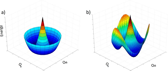
Effect of a nonzero quadratic Jahn–Teller effect on the ground-state APES. (a) Linear JT effect, (b) linear and quadratic. For clarity, only the lower surfaces are shown. Note: in generating these surfaces SOC has not been incorporated, following the hierarchical DFT treatment below. For 1, Qε is defined as a B–Fe–N bend within the Cs plane of symmetry toward or away from one of the carbene atoms, while Qθ is defined as an B–Fe–N bend orthogonal to Qε.
The PJT distortion and SOC lead to pronounced deviations of the g values from ge. To describe the g values of 1, its [ea3] configuration can be treated as a single hole in the ea doublet, with the ground-state electronic energies and wavefunctions at the equilibrium value of the distortion. The mixing and splitting of the two components of 2E can be described formally in terms of a dimensionless parameter, r, the ratio of the sum of the vibronic and “crystal field” matrix elements, V = Vvib + VL, to a SOC parameter, λ, r = 2V/λ. This parameter λ traditionally corresponds to the ionic SOC constant, λSOC, multiplied by a “covalency parameter”, k = k0, defined such that (1 – k0) represents the fraction of d-electron density delocalized onto the ligands; (1 – k0) → 0 in the absence of covalency. For typical d-electron delocalization of (1 – k0) ∼ 10%, k0 ∼ 0.9, the ratio 2 V/λ = r fixes the energies and wavefunctions of the distorted state and is conveniently parametrized in terms of a fictitious angle, 2θ.47
| 3 |
The g values for the ground Kramers doublet of the distorted [ea]3 state are conveniently written in terms of the fictitious angle and k:
| 4 |
The angle 2θ, and thus the ratio r, can be determined from g⊥, and the parameter k can be determined from g∥.
Treating the measured g values with eq 4 gives r = 7.1 and k = 0.54, and Figure 4 presents plots of eq 4 for this value of k as well as for the crystal-field limit, k = 1.0. An interpretation of the anomalously low value of k, in terms of spin occupancy on Fe clearly is nonphysical, and indeed CASSCF/NEVPT2 computations (below) suggest that the Fe spin density is in accord with k → 1.0, which is in agreement with conventional treatments of k0. However, this value can be understood by noting that the idealized trigonal symmetry of 1 is ∼C3v not D3h, and placing this in the context of a recent report that analyzes the consequences of lowering the symmetry of a trigonal metal-ion site, such as that in 1, from D3h to C3v. This report shows that an increase of the three X-Fe-L (X = N in 1) angles from 90° in D3h symmetry by an angular deviation, δ (Figure 5), does not change the order of the ligand-field orbitals (Scheme 1) but causes mixing of the eb orbitals into the ea orbitals (and vice versa).48
Figure 4.
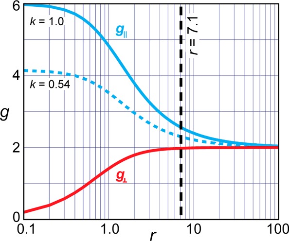
Plot of g values for the [e]3 configuration as a function of r (eq 4). The solid blue line represents the crystal-field limit, k = 1; dashed blue represents measured k = 46%; the vertical black dashed line indicates the solved r = 7.1 for g∥ = 2.30 and g⊥ = 1.98.
Figure 5.
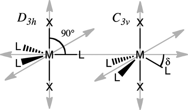
ML3X2 in D3h (left) and C3v (right) symmetry depicting the δ angular deviation of L from the D3h symmetry plane (σh) when in C3v symmetry.
In fact, e–e mixing caused by the extreme “doming” of the Fe atom out of the C–C–C plane of the chelating ligand of 1 explains the “reversed” ordering of the two e orbital doublets in 1. In the simple angular overlap method (AOM) treatment48 the extent of e–e mixing is simply determined by the angular deviation, δ (Figure 5). In D3h symmetry, one expects a ground eb, ml = ± 1, doublet; as the angular distortion, δ, increases, the ea (ml = ± 2) doublet increasingly mixes with eb. For δ > 26.56°, ea actually becomes the major component of the lower-lying, occupied doublet, causing the apparent “switch” in orbital ordering: the ground doublet becomes predominantly ea (ml = ± 2), into which is mixed a minority component of the eb (ml = ± 1) wave function.
The formal theory that relates covalency, vibronic coupling, and SOC (eq 3) is not altered in form by e–e orbital mixing, but the mixing modifies the parameters that determine the g values. The covalency parameter for the [ea]3 configuration of 1 becomes
| 5 |
where b2 is the contribution of the eb orbitals to the nominally ea ground doublet, with an ea contribution of a2 (a2 > b2, a2 + b2 = 1), and this equation allows an estimate of the e–e mixing from the measured g values. Taking k0 = 0.9, the value, k = 0.54, obtained from analysis of the g values yields as the coefficient for mixing eb into ea, b2 ∼ 0.3. This mixing of eb into ea for 1 is large compared to the complementary mixing of ea into eb in Schrock’s PJT-active [eb]3 MoIII–L complexes, L = N2, CO, NH3 (2). The Mo complexes are much less domed, with a deviation from D3h of only δ = 12° for L = N2, and the corresponding analysis yields e–e mixing of only 5%. The PJT parameter r = 7.1 for 1 is 5.5-fold larger than that for the MoIII complexes (r = 1.3). This difference can be factored roughly equally into a more than 2-fold larger value of λ for MoIII (as both λSOC and k of eq 3 are larger), which acts to suppress a JT distortion for the Mo complexes, and a comparably larger coupling, V for FeV of 1 (eq 3). The larger V for 1 in turn reflects the fact that in the presence of e–e mixing, V becomes a sum of distinct vibrational contributions of both symmetries dependent on the amount of orbital mixing, V = a2Va + b2Vb. Together, these two effects drive the distortion of 1, as compared to that of the MoIII complexes, and lead to the strong JT distortion observed for this Fe(V) complex.
As shown below, this large mixing of ea into eb is confirmed by DFT computations and results in the large orbital vibronic constant, r, that generates the C3v → Cs distortion in 1. Likewise, it is shown that a contribution by distortions of both ea and eb symmetries is key to understanding the properties of 1.
The model described by eqs 4 and 5 not only rationalizes the observed g values but also provides a basis for understanding the anisotropic EPR line widths. The broad g∥ feature and much narrower g⊥ feature (Figure 2) result from a distribution in the parameter, r (eq 3), which yields a distribution in g values (eq 4), commonly referred to as ‘g strain.’ A distribution of width, ± δr, would yield a spread in g values of ± δg∥/⊥
| 6 |
which in turn leads to a differential line broadening:
| 7 |
where the derivatives are obtained from eqs 3 and 4. The ratio of the line widths (legend to Figure 2) at g∥ and g⊥ as calculated for r = 7.1 is well described by the ratio of derivatives, eq 6; the line widths themselves correspond to a small distribution, δr ∼ ±0.02, around the average value, r = 7.1.19,47
ENDOR Spectroscopy
Nitride
At the low-field, g∥ edge of the EPR signal of 1, the 14N ENDOR spectrum exhibits a single feature at a frequency above the 14N (I = 1) Larmor frequency, vn ∼ 4 MHz (Figure 6, black). An assignment of this peak as the v+ = 7.8 MHz branch of a 14N ENDOR signal from a nitride without resolved quadrupole splitting is confirmed by the corresponding spectrum for 1-15N in which the nitride is 50% 15N labeled (Figure 6, red). This spectrum shows a new peak that can be assigned as v+ = 10.8 MHz from the 15N (I = 1/2) nitride. According to eq 1, these v+ peaks correspond to |Ag∥(14N)| = 9.1 MHz, and match |Ag∥(15N)| = 12.8 MHz, scaled up to a higher coupling corresponding to the ratio of the nuclear g factors, |g15N/g14N| = 1.41.49 At the high-field edge (g⊥ = 1.98) of the EPR spectrum, the 14N sample (black) exhibits intense features below 8 MHz that arise from 14N of both the carbene ligand and nitride. Partial labeling of the nitride again gives a single 15N feature; its frequency, v+ = 10.5 MHz, corresponds to a coupling, |Ag⊥,max(15N)| = 9.6 MHz. As indicated on the spectrum, v+(14N) falls at the high-frequency edge of the overall 14N ENDOR pattern. This correlation shows that the 14N nitride also does not exhibit a resolved quadrupole splitting at g⊥, as such a splitting would create a doublet centered at the indicated v+(14N), but split by the 14N quadrupole interaction. If this were the case, the higher-frequency partner of this quadrupole doublet would appear beyond the high-frequency edge of the observed 14N ENDOR signal, contrary to observation (Figure 6, black).
Figure 6.
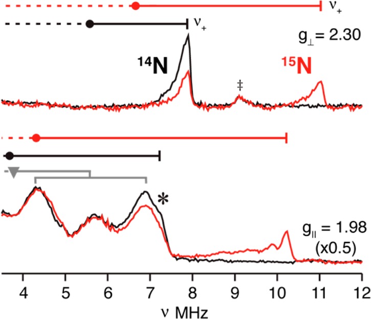
14/15N ENDOR spectra of 1 collected at g∥ and g⊥: black, 14N nitride; red, 50% isotopically 15N-enriched nitride. 15N hyperfine couplings associated with g∥ and the maximum value at g⊥ were calculated the nu+ frequencies, Ag∥(15N) = 12.8, Ag⊥,max(15N) = 9.6 MHz. The frequencies of the corresponding 14N v+ features match the frequencies calculated by scaling the 15N hyperfine couplings with the ratio of the nuclear g values, Ag∥(14N) = 12.8, Ag⊥,max(14N) = 9.6 MHz and assuming the absence of a quadrupole splitting in the 14N spectrum (see text). Circles correspond to the hyperfine frequencies (A(14,15N)/2); goalposts indicate splittings by the corresponding nuclear Larmor frequencies. Gray goalposts (g = 1.98) represent hyperfine and quadrupole splitting for 14N of the tripodal ligand (see Figure S2). (‡) indicates the 1H line excited by the fifth rf harmonic.
The 15N nitride signal overlaps with signals from 14N at intermediate fields, but the full 15N hyperfine tensor nonetheless could be obtained by fitting the evolution of the v+(15N) branch of the spectrum as the field is increased from g∥ until it is lost in the background 14N signal from the imidazole-2-ylidene group of the ligand. This 2D field-frequency pattern of ENDOR spectra is well described by the hyperfine tensor, |A(15N)| = [A1, A2, A3] = [12.8, 9.6, 1.0] MHz (aiso = 7.8 MHz), with A1 parallel to g∥ and A2,3 lying in the g⊥ plane, Figure 7.
Figure 7.
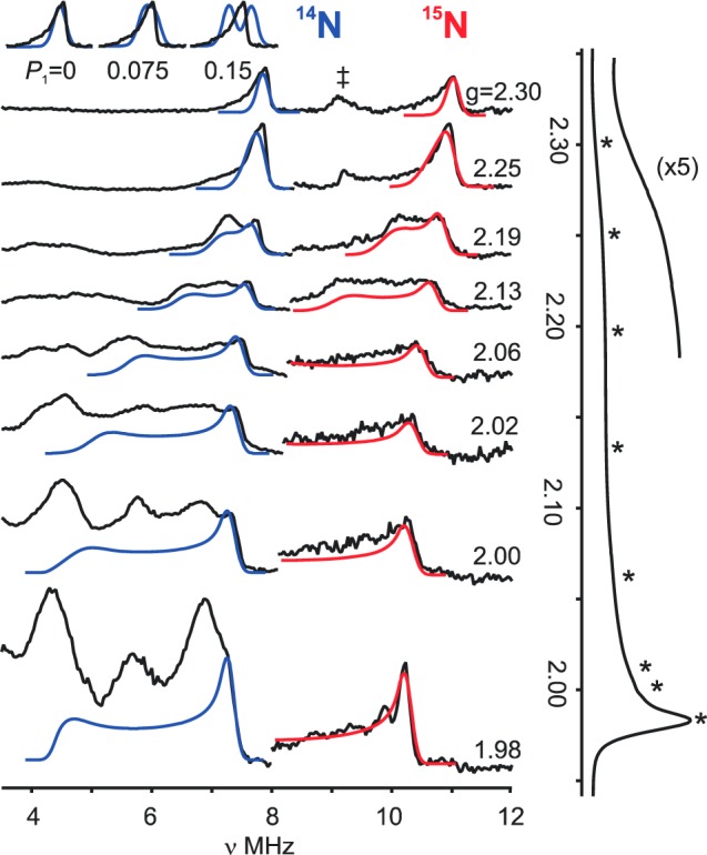
Q-band 2D Davies pulsed 14,15N ENDOR 2D field-frequency patterns for 1(14,15N-nitride). Right: 15N ENDOR species (black), simulations (red). Simulation parameters: A(15N) = [12.8, 9.6, 1.0] MHz, coaxial with g; ENDOR line width 0.25 MHz; EPR line width, 500 MHz. Left: 14N ENDOR spectra (black), simulations (blue). Simulation parameters: g = [2.30, 1.98, 1.98]; A(14N) = −[9.1, 6.84, 0.71] MHz, P = 0 MHz; with A coaxial to g; line widths as with 15N. (‡) indicates the 1H line excited by the 5th rf harmonic. Inset: Simulation for 14N spectrum with increasing quadrupole coupling, P1/MHz (P2 = P3 = −P1/2) overlaid on v+(14N) feature at g∥ = 2.30. Far right: ESE-EPR spectra of 50% 15N labeled FeV nitride complex as described in Figure 2. (*) indicates ENDOR field positions. Conditions: microwave freq, 34.96 GHz; π pulse length = 200 ns; τ = 600 ns; repetition rate, 20 ms; Trf = 30 μs; rf randomly hopped.
Scaling the 15N hyperfine tensor by the ratio of the nuclear g factors yields, |A(14N)| = [9.11, 6.84, 0.71] MHz. Simulations with this tensor accurately reproduce the resolved nitride 14N features in the 2D ENDOR pattern of Figure 7 without the inclusion of any14N quadrupole interaction the I = 1 14N nitride. Simulations shown in the inset to Figure 7 demonstrate that the absence of any resolved quadrupole splittings in such well-resolved spectra, and indeed the ability to use the same ENDOR line width in simulations of the 14N and 15N spectra requires the components of the quadrupole interaction tensor to be vanishingly small, Pi ∼ 0 MHz: Pmax < 0.03 MHz. To set a standard for comparison, for an R–C≡14N, Pmax ≈ 2 MHz.50
As a final note about the simulations, they show that the “tailing” to low frequency of the v+ features of both the 14N and 15N samples in spectra collected at the g∥ = 2.30 low-field, “single-crystal-like” edge of the EPR spectrum (Figure 7) is a result of the large EPR line width associated with g∥, assigned above to “g strain”.
The simulations of the 2D ENDOR patterns show that all three elements of the 14,15N hyperfine tensors have the same sign. The absolute signs of both 14N and 15N tensors were determined by PESTRE measurements on the v+ peaks at the fields near g∥, Figure 8. Based on the criteria by which the sign of the coupling is determined by the sign of DRLδ, the measurements reveal that A(14N) < 0 and A(15N) > 0 for the nitride, with the difference in signs determined by the signs of the nuclear gn factors.31 Thus, the final nitride hyperfine tensors are, A(15N) = +[12.8, 1.0, 9.6] and A(14N) = −[9.11, 0.71, 6.84] MHz.
Figure 8.
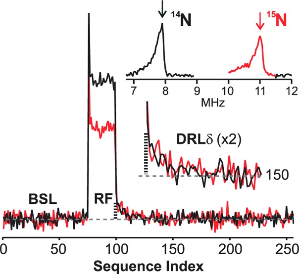
Absolute hyperfine sign determination of nitride by PESTRE. Davies pulse sequence at 34.97 GHz; magnetic field position, 10930 G; π = 120 ns; τ = 600 ns; repetition rate, 20 ms; Trf =30 μs; rf frequency, 7.9 MHz (14N) and 11.0 MHz (15N); tmix =5 μs; 14/15N ENDOR (upper-right inset): π = 200 ns; τ = 600 ns; repetition rate, 20 ms; Trf = 30 μs; rf frequency randomly hopped.
Nitride Hyperfine and Quadrupole Analysis
We first address the 15N hyperfine coupling tensor, A, which is the sum of the isotropic term, aiso, and dipolar term, Tobs (eq 8).
 |
8 |
The 15N isotropic coupling, aiso(15N) = +7.8 MHz corresponds to a negligible unpaired s orbital density on N. Taking aiso0 (15N) = −2540 MHz for a single electron in a 2s orbital,49 one obtains a 2s orbital density for the nitride of 1, ρs ≈ −3 × 10⁻³. Thus, the nitride can, in first approximation be treated as having a filled 2s orbital, with bonding to Fe involving essentially unhybridized p orbitals.
Following published procedures,51Tobs can be uniquely decomposed into two axial contributions. One is a local contribution from spin density on N and has its unique axis along an axis (x or y) orthogonal to the Fe–N bond, Tx,yloc (SI). The second has a unique axis (z) along the Fe–N bond, Tzobs, and is made up of a nonlocal (nl) contribution from through-space dipolar interactions between the 15N and electron spin on iron, and a local (l) contribution from 2p orbital spin density on nitrogen. The nl contribution can be estimated from the point-dipole interactions of the nitride and Fe (SI). Subtraction of the nl contribution from Tobs yields the local dipolar contribution, Tloc = Tx,yloc + Tzloc which can be viewed as arising from spin density transferred to an idealized N3– via electron donation from filled orbitals on N to partially occupied dδ(xy, x2–y2) orbitals on FeV and/or polarization of the filled 2p orbitals on N. As detailed in the SI, the spin densities in the three 2p orbitals of the nitride can be estimated from Tloc and are found to be quite small and anisotropic: ρx ∼ 0, ρy = −0.04, ρz = −0.08. These spin densities match well the computed DFT values, presented below.
Analysis of the quadrupole interaction gives information about the charge density in p orbitals on nitride. The charge on the nitride ligand of 1 is decreased from that of an idealized nitride trianion by charge donation from the doubly occupied 2p orbitals of nitride into the empty dσ(z2) and dπ(xz, yz) orbitals of FeV. An analysis of the charge densities in the nitride 2p orbitals obtained by consideration of 14N quadrupole interactions parallels the analysis of the spin densities based on 15N hyperfine interactions, above. According to the approximate Townes–Dailey model for the quadrupole interaction,50 the individual tensor elements, Pi, i = 1–3, for 14N are proportional to the asymmetry in the number of electrons in the three p orbitals:
 |
9 |
where N̅jk is the average of the occupancies of the two 2p orbitals orthogonal to 2pi. The upper limit on the quadrupole coupling, for all three components, |Pi| < 0.1 MHz (Figure 7, top), implies that |Ni – N̅jk| < 0.003 (taking e2Qq0 = −9 MHz for 2p orbital of 14N)50 for the three 2p orbital populations, namely that, each 2p orbital donates electrons equally to Fe and donation from the nitride 2pσ orbital along the Fe–N axis equals the average donation from the 2pπ orbitals orthogonal to it, leaving the charge density on the nitrogen atom with spherical symmetry. This analysis does not, however, indicate the actual extent of charge donation (denoted, d), nor give information about the actual charge of the nitride, N–(3–d).
Nuclei of the Tripodal Ligand
11B
Mims ENDOR spectra reveal well-defined quadrupole splittings of the v+ and v– branches from an 11B with small hyperfine and quadrupole couplings, Figure 9. The 2D field frequency pattern can be described by an axial hyperfine tensor, A = [1.1, −1.45, −1.45] MHz, and an axial quadrupole interaction, P = [0.24, −0.12, −0.12] MHz, each coaxial with g, with the unique component of each tensor lying along g∥ (Figure 9)
Figure 9.
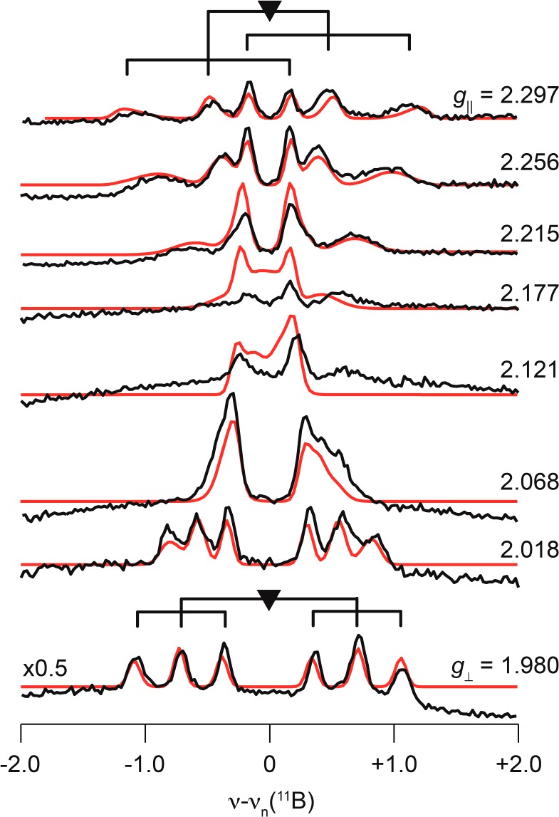
Q-band 2D field-frequency Mims pulse detected 11B ENDOR. Simulation parameters: g = [2.30, 1.98, 1.98]; A = [1.1, −1.45, −1.45] MHz, P = [0.24, −0.12, −0.12] MHz; both A and P coaxial with g; ENDOR line width, 0.11 MHz; hyperfine strain [7 1 1] × 100 MHz. Conditions: Microwave freq, 34.914 GHz; π pulse length = 50 ns; τ = 500 ns; repetition rate, 20 ms; Trf = 30–60 μs; rf randomly hopped.
The 11B hyperfine coupling tensor can be decomposed into dipolar and isotropic contributions, T = A – aiso = [2T, −T, −T] = [1.7, −0.85, −0.85] MHz, aiso = −0.6 MHz; the axial character, magnitude, and sign of T are as expected for a through-space interaction with the positive spin density on Fe center. The small magnitude of the isotropic hyperfine coupling to 11B indicates that it has negligible bonding interactions with the FeV ion are negligible. The negative sign of aiso implies that the spin density on 11B is negative, as predicted computationally (see below), and arises from spin polarization, as does the negative spin density of the nitride.
The 11B quadrupole tensor has axial symmetry, indicating that the three B–N bonds are equivalent, with effective C3v symmetry at boron, in keeping with the crystal structure. The small value of the experimentally derived quadrupole coupling parameter, e2qQ = 2P1 ≈ 0.5, compared to the intrinsic coupling constant for a single 11B electron in a 2p orbital: |e2qQ0| ≈ −5.3 MHz, is shown in SI to follow for the trigonal sp3 boron with three B–N single bonds and a single B–C bond.
It is interesting to further note that the breadths of the three peaks in each of the v± manifolds increase with the mI index of eq 2.52 This implies the presence of a small “quadrupole strain” that is correlated with a small “hyperfine strain”, this correlated variation in A and P associated with the “g strain” discussed above and well simulated for the 11B ENDOR pattern by the inclusion of anistotropic hyperfine ENDOR line widths, providing more width along g∥ match the wider EPR line width.
13C
An isotropic hyperfine natural abundance 13C Mims ENDOR pattern was found with aiso ∼ 0.9 MHz; no signals are detected from 13C with a larger coupling as anticipated from Fe–C bonds (Figure S1). We surmise that signals from the coordinated carbene 13C, which are expected to be strongly coupled (see below) are too broad and weak to be detected in natural abundance, and that the observed signal is associated with the “distant” 13C of the imidazole-2-ylidene group of the ligand.
14N
The low-frequency 14N peaks observed at fields approaching g⊥ arise from 14N of the tridenate ligand as noted above (Figure 6 and 7). The six poorly resolved nitrogen signals are simulated together as shown in Figure S2.
Electronic Structure Computations
Here, we use SO-DFT methods to estimate the relative magnitudes of PJT and SOC effects. Although the DFT methods reproduce the ground state geometries, the CASSCF/NEVPT2 treatment results in a substantial improvement when describing the subtle aspects of the spin-density and state energetics responsible for the measured hyperfine, quadrupolar, and g tensors. We discuss in detail the consequences of a strong PJT effect on Fe≡N bonding, which leads to an orbital model that describes the electronic origin of the PJT distortions and the nature of the these distortions. Here, we define z as along the Fe–N bond, and the computational analysis of the hyperfine (vide infra) provides a convenient definition of x and y, with the xz plane being defined as the Cs plane of symmetry and containing N, Fe, and one of the carbene C atoms.
Energetics of the JT Effect
The formal two-state model described above can be understood at a fundamental level by employing a complete active space self-consistent field (CASSCF) approach to the electronic structure of 1. Such a multireference wave function method is required for handling problems with ground state orbital degeneracy or near-degeneracy, as discussed for the trigonal MoIII–N2 system by McNaughton et al.19,47 The qualitative molecular orbital diagram for the DFT geometry-optimized (JT-distorted) 1 that results from these calculations is depicted in Figure 10. The degeneracy of the Fe ea orbital set [d(x2–y2),d(xy)] is removed by a combination of the JT distortion and SOC within the 2E ground state. However, in 1 the Fe SOC constant is smaller and the vibronic coupling much stronger than in the case of the MoIII–N2 system (2, see above).19,47 Thus, self-consistent SO-DFT calculations on the high-symmetry (C3v) optimized 1 reveal that the SOC splitting of the 2E state is only ∼300 cm–1, more than an order of magnitude smaller than the DFT calculated JT stabilization energy of ∼4000 cm–1. As a result, in the DFT computations it is more convenient to determine the vibronic distortion of 1 by optimizing the structure hierarchically, first optimizing the geometry of 1 as a true JT system while ignoring the SOC and then introducing SOC as a perturbation in the distorted geometry in order to determine SOC-dependent properties such as spin-Hamiltonian parameters.
Figure 10.
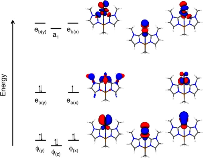
Molecular orbital diagram derived from SA-CASSCF(8,9) calculations (active space orbitals shown).
The DFT-optimized geometry of 1 is in good agreement with the published crystal structure of the complex,9 which justifies our neglect of self-consistent SOC effects associated with the low-symmetry geometric distortion. In particular, the calculated Fe–N bond distance and the B–Fe–N angle (nitride bend), r(Fe–N)=1.53 Å, and ∠(B–Fe–N) = 171°respectively, compare quite well with r(Fe–N) = 1.51 Å and ∠(B–Fe–N) = 173.6° for the 35 K crystal structure. CASSCF/NEVPT2 calculations performed on this geometry-optimized structure yield g∥ = 2.48 and g⊥ = 1.98. The computed g⊥ = 1.98 is in excellent agreement with the experimental value, and the computed g∥ = 2.48 is in qualitative agreement with the experimental value of g∥ = 2.30. The deviation of the computed g∥ from the experimental value primarily arises because the calculations underestimate the splitting of the 2E ground state due to the JT distortion. TD-DFT calculations have been used to provide an estimate for the 2E level splitting of ∼4000 cm–1, whereas the CASSCF/NEVPT2 method results in a smaller calculated splitting of ∼2900 cm–1 for the 2E ground state. Manual adjustment of the diagonal energies used in the g tensor calculation of the 2E → 2E (ea(y) → ea(x)) state energy gap to 4000 cm–1 results in improved agreement (g∥ = 2.40) with the experimental g∥ without affecting other parameters. This is indicative of the extreme sensitivity of g∥ to this energy gap parameter. This process of determining the 2E(ea(y)–ea(x)) splitting from g∥ is analogous to deriving the PJT parameter, r, from g values.
The SOMO wave function of the geometry-optimized structure, calculated by CASSCF/NEVPT2, possesses 55% d(x2–y2), 19% d(xy), 14% d(xz), and 5% N p(x) (i.e., 20% eb) orbital character, in excellent correspondence with the ea–eb adjusted LF model. The relative orbital contributions to the SOMO result from a combination of strong ea–eb mixing and the strong JT splitting of the 2E ground state. Taken together, these effects result in a small rotation of the nominally “in plane” SOMO out of the molecular xy plane and into the molecular yz plane. This also provides a mechanism for a small degree of N px character admixed into the SOMO which has implications for understanding the nature of the 14N and 15N hyperfine tensors, vide infra. Finally, the 14% d(xz) metal character present in the SOMO explicitly demonstrates and confirms the strong ea–eb mixing inferred from the nonphysically small value of the “covalency” parameter, k, derived in the formal analysis of the g values.
Vibronic Coupling
This description of ea–eb orbital mixing introduces a mechanism by which quadratic JT effects can contribute to the static vibronic distortion observed in 1. The vibronic coupling operator, W(r,Q), is commonly written as an expansion in normal coordinates, Q:
| 10 |
where QΓ and QΓ′ are a general normal coordinates.
The first term gives matrix elements of the form:
| 11 |
where the FΓ(ij) are the linear vibronic constants, the Ψn, are electronic states of the molecule, and QΓ is a normal coordinate of the molecule. These vibronic constants can be diagonal (i = j, normal JT effect) or off-diagonal (i ≠ j, PJT effect, i.e., mixing of different electronic states that are split from each other by SOC), depending upon the symmetry of the active normal mode and the energy splitting of electronic states. The linear vibronic constant involving a 2-fold degenerate electronic state and 2-fold degenerate vibration (E × e problem) gives rise to the JT distortion and distorted APES. This is illustrated by the APES in Figure 3a, commonly known as the “Mexican hat” potential, with the Fij corresponding to a component of the Vvib in the formal PJT theory. This surface leads to a dynamic system, where the molecular distortion freely pseudorotates through the circular vibronic minimum unless an additional potential (VL in the formal theory) is applied, localizing the distortion by modifying the APES. The second term in the vibronic operator expansion results in matrix elements known as the quadratic vibronic constants, GΓ(ij):
| 12 |
where i ≠ j. Nonzero values of Gij result in a further warping of the APES to give the “tricorne hat” potential (Figure 3b) which has three distinct minima. If the barrier between the tricorne hat minima is greater than the available thermal energy (kT), the molecule is trapped with equal probability in one of the three wells and becomes statically distorted, even in the absence of any external potential, VL.
To understand the orbital contributions to the JT effect, the above linear integral vibronic constants can be written as a sum of orbital vibronic constants:
| 13 |
which allow for an intuitive orbital description of the electronic structure effects that lead to a PJT distortion.
To map out the JT potential energy surface for 1, we first attempted to project CASSCF-derived Cartesian geometry differences onto particular vibrational modes. It was intended to use these modes as an APES scan coordinate, beginning at the three-fold symmetry point, allowing for determination of JT parameters by curve fitting. To begin, a high symmetry geometry was obtained by averaging the CASSCF wave function over both components of the lower E level, while a low-symmetry geometry was obtained by optimizing the geometry of the ground state only. Next, the Cartesian differences were projected onto the normal modes obtained by a vibrational frequency calculation at the high symmetry (C3v) geometry. However, as observed with 2(47) the distortion was described as a linear combination of several normal modes, precluding a straightforward normal mode scan. As a reasonable approximation to the full PJT APES, we used DFT geometry scans to determine the energetics of the C–Fe–N angle (nitride “tilt”, Figure 11, left) and a N–Fe–B–C dihedral (nitride “rotation”, Figure 11, right) distortions, which result in two slices of the full 2D JT APES. This provides a qualitative description of the APES, and enabled the identification of several features characteristic of a quadratic JT effect, including three global minima with saddle points opposite each minimum.
Figure 11.
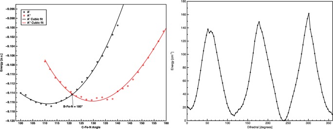
Left, relaxed PES scan along a C–Fe–N angle. Right, nitride “rotation,” with N–Fe–B angle fixed to minimum. PBE/TZP, ADF2012.01.
As seen in Figure 11, a DFT geometry scan of any one of the three symmetry-equivalent C–Fe–N nitrido bends yields a minimum positioned opposite a maximum, indicating that the APES of 1 corresponds to the tricorne hat associated with a quadratic JT effect, with each of the three maxima corresponding to saddle points along the slice of the APES described by the B–Fe–N bend. The APES scan reveals a crossing in the energies of the d(xy) and d(x2–y2) (i.e., ea(1) and ea (2) in C3v symmetry) orbitals as a function of nitride bending. This conical intersection at the high-symmetry (C3v) point of instability is suppressed when 1 is treated as a PJT system, and SOC and vibronic coupling are treated in parallel, rather than hierarchically. Although these gas phase calculations clearly indicate the presence of a quadratic JT distortion, this does not preclude contributions from an additional VL term in the condensed phase. The presence of a VL contribution arising from environmental effects would further distort the APES by tilting the tricorne hat and localizing the experimentally observed Cs distortion along one slice of the otherwise three-fold degenerate JT APES.
With respect to the relative magnitudes of Vvib and VL, it was previously determined that Vvib > VL for compound 2. The presence of strong e–e orbital mixing in 1, which is found even in rigorously C3v calculations (but which would be absent in D3h), contributes to a markedly stronger Vvib contribution in 1 (Figure 12). This is evidenced by the strong reduction in g tensor anisotropy for 1 compared with 2, and the appearance of a rhombic 14,15N A tensor. Taken together, this suggests that the large Vvib contribution to V leads to a strong quadratic JT perturbation on the ground state APES of 1, with any VL contribution being of secondary importance. The effect of the strong e–e mixing is also clearly evident in the Fe–N bonding scheme, which provides an orbital description for the origin of the JT distortion. In the absence of e–e mixing (Figure 12, left) the d(xy) and d(x2–y2) orbitals lie in the molecular xy plane and are therefore nonbonding with respect to the Fe–N interaction. This results in the orbital vibronic constants being zero, no orbital driving force for a symmetry-lowering JT distortion, and an axial 14,15N A tensor. The e–e mixing (Figure 12, right) tilts the d(xy) and d(x2–y2) orbitals out of the molecular plane and introduces nonzero linear and quadratic orbital vibronic constants. As a result the JT effect is now active and the molecule can distort, removing the three-fold symmetry (C3v → Cs).
Figure 12.
Result of e–e orbital mixing on the orbital vibronic constants. This mixing results in nonzero vibronic constants in both e levels.
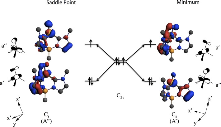
We have shown that distortion of 1 along the nitride bending coordinate (i.e., the C–Fe–N angle, see Figure 11) changes the d orbital manifold in several ways (Figure 13). Depending on whether the direction of the orbital tilt is toward a minimum or a saddle point of the APES, a different electronic state (A′ or A″, in Cs symmetry) is selected. This is based on the specific nature of the antibonding interactions between the iron e orbitals and nitrido px,y orbitals. We find that the minimum on the APES is the A′ state with an [a″]2[a′]1 electronic configuration. Figure 13 depicts how the nitrido bending decreases the Fe–N π-antibonding interaction in the doubly occupied a″ orbital and increases the Fe–N pseudo-σ antibonding interaction for the singly occupied a′ orbital. Conversely, the A″ state that possesses an [a′]2[a″]1 electronic configuration is a saddle point on the APES. As the A′ state is the ground state, the bending-induced reduction in the Fe–N π-antibonding interaction dominates over a reduction in the pseudo-σ antibonding interaction in determining the nature of the low-symmetry distortion and ground state of 1.
Figure 13.
DFT results detailing the effects of the JT distortion on nitride orbital orientation and state selectivity. Distortions along the B–Fe–N angle result in different electronic ground states being selected that may affect reactivity in Fe≡N and related systems.
Spin-Hamiltonian Parameter Computations
Here we analyze hyperfine and quadrupolar couplings in the context of spectroscopic and bonding calculations using spin-unrestricted DFT CASSCF/NEVPT2 methods. The computational results are interpreted in the context of e–e orbital mixing, which provides a mechanism for a quadratic JT effect that contributes to the observed static vibronic distortion of 1.
14N Nitride Hyperfine Interactions and the g-tensor
Spin-unrestricted DFT calculations show a markedly larger 14N dipolar hyperfine than observed by experiment (Table 1). This increased 14N hyperfine arises from an overestimation of iron–nitrogen orbital mixing in the SOMO, also described as an imbalance in the relative contributions of ionic and covalent terms in the CI expansion of the wave function. CASSCF/NEVPT2 calculations provide much-improved 14N hyperfine and g tensor components (Table 1). Calculations of the 57Fe quadrupole splitting also have been made and are in excellent agreement with the experiment (see SI). This improvement does not appear to be due to any inherent multireference character of 1 (as compared to the strong multireference character in 2), as the JT distortion of 1 results in a predominately single-reference wave function (>80%). The poor agreement between the experimental g tensor and that obtained by DFT likely arises from a large out-of-state SOC with the first excited 2E state; the magnitude of the spin-orbit mixing is large and is likely out of the range appropriate for linear-response DFT g tensor calculations implemented in ORCA.53 Alternatively, overestimation of Fe–N covalency results in an excess of spin delocalization away from Fe, reducing the g-shifts by a reduction in metal spin density. It must be emphasized that the computational errors in the DFT-derived spin density are not large absolute errors, as the spin density accounts for only a vanishingly small fraction of the total charge density.
Table 1. Hyperfine Coupling Tensor A, Dipolar Coupling Tensor T, and Quadrupole Tensor P for FeV–14N(nitride) Obtained from the Spin-Unrestricted PBE0-DFT and CASSCF Calculationsb Compared with Experimental 14N ENDOR Valuesa.
| A1 | A2 | A3 | aiso | T1 | T2 | T3 | P1 | P2 | P3 | |
|---|---|---|---|---|---|---|---|---|---|---|
| 14N DFT | –28.0 | –19.6 | 1.2 | –15.5 | –12.5 | –4.1 | +16.7 | –0.057 | –0.067 | 0.124 |
| 14N DFT/3 | –9.33 | –6.5 | +0.4 | –5.2 | –4.2 | –1.4 | +5.6 | –0.019 | –0.022 | 0.041 |
| 14N CAS | – | – | – | –c | –4.26 | –1.58 | +5.84 | 0.10d | 0.14 | –0.24 |
| 14N exp | –9.11 | –6.84 | –0.71 | –5.55 | –3.56 | –1.29 | +4.84 | ∼0 | ∼0 | ∼0 |
All values in units of MHz.
All calculations performed on DFT minimized geometry.
aiso could not be accurately calculated by CASSCF methods due to severe convergence difficulties when including N 2s orbitals in the active space.
P3 = 2[e2qQ/(4I(2I – 1)] MHz; η = (P1 – P2)/P3 = 0.163.
The nitrogen spin density is subtly, but critically, different in the two computational descriptions of the electronic structure. The DFT computations predict a simple delocalization of spin from the nominally “non-bonding” (predominantly ea) Fe orbitals into the Fe–N π* (eb) orbitals that is enabled by the ea–eb Fe d orbital mixing. This mixing is extremely important, as it results in a large transfer of positive spin density from the Fe to the terminal nitrido, and a markedly larger dipolar hyperfine component. The CASSCF calculations suggest a large asymmetry in the spin density that correlates with the computed principal components of the 14N hyperfine tensor (Figure 14). The CASSCF calculations describe a toroidal spin density distribution about the terminal nitride, with larger lobes of spin localized in the molecular yz plane and reduced negative spin density along the x-axis (Figure 14). This reduction in spin density along the x-axis arises from a near cancelation of negative and positive spin density along this axis, with the latter arising from Fe≡N covalency. As depicted in Figure 12, the rotation of the nominally “in-plane” SOMO about the molecular y-axis allows for a small degree of N px character to be admixed in the SOMO wave function, and this provides a mechanism for a small positive contribution to the spin density at the terminal nitride along the x direction. This orbital rotation is present even in rigorously high (C3v) symmetry, underscoring key contributions from the strong carbene ligand field and the extreme “doming” of the Fe atom out of the C–C–C plane of the chelating ligand. We note that in the approximate Cs geometry of JT distorted 1, positive spin populations cannot occur in the molecular y and z directions via a spin delocalization mechanism, since there is no covalent mixing of the N py or pz orbitals in the SOMO of 1. Negative contributions to the nitride spin density arise from spin polarization of the N px, py, and pz orbitals by the spin on Fe, which can be described by configuration interaction. In contrast to the anisotropic spin distribution, the terminal nitride maintains a nearly spherical charge distribution, as evidenced by the small experimental and calculated quadrupole coupling constants. Thus, the combined effect of spin delocalization and surprisingly large spin polarization do not appear to grossly affect the overall charge distribution on the terminal nitride.
Figure 14.
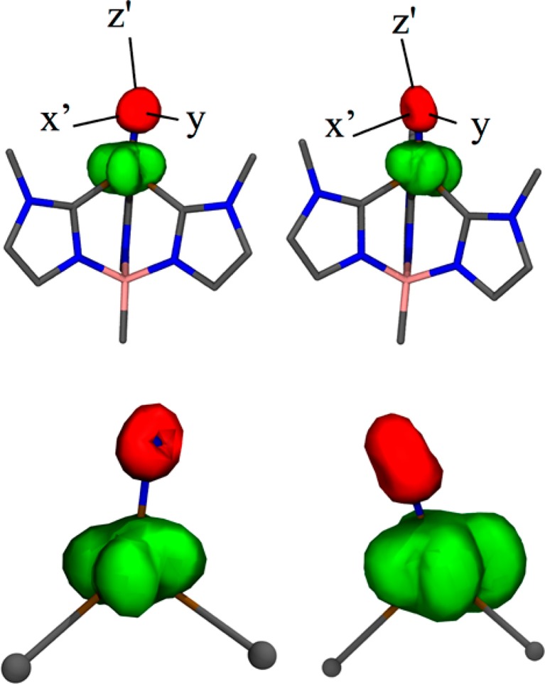
CASSCF calculated spin density for 1 (left: saddle point, A″ right: minimum, A′); green: positive spin density, red: negative spin density. Hydrogen atoms omitted for clarity. The nitrido tilt (within the Cs plane) connects the two states by bending toward (A′), or away (A″) the carbene on the left of the figure. The axis superimposed on the upper figures show the principle axes of the 14N hyperfine tensor.
14N Nitride Quadrupole Coupling
The DFT computations indicate that the electronic origin of the near-spherical nitride charge density is not simple, arising from two competing effects. The overlap integral between the filled 2pσ of nitride and empty 3d(z2) of Fe is expected to be much greater than that between the two filled 2pπ nitride orbitals and the empty 3d(xz/yz) orbitals on Fe which would enhance σ donation. However, previous work15 shows that the Fe 3d(z2) orbital is significantly hybridized with the Fe 4p(z) orbital, and this hybridization substantially contracts the d(z2) lobe that is oriented in the direction of the nitride. This has the effect of reducing the 2pσ–3d(z2) overlap and the amount of N p(z) → Fe 3d(z2) charge donation. These competing effects lead to the experimental 14N hyperfine and quadrupole results for 1, which show that σ and π donation are nearly equivalent.
The DFT computations capture the near spherical nature of the nitride, as a small anisotropy in the Mulliken orbital populations, N∥ – N̅⊥ = 0.06 and a small calculated e2qQ. This is in quite satisfactory agreement with the small orbital population difference approximated with the Townes–Daily analysis of the 14N ENDOR data; in both cases the absolute differences correspond to only a small fraction of an electron. Using the CASSCF-computed population asymmetry of 0.06, a simple Townes-Daily analysis (eq 9) yields e2qQ = −0.54 MHz (i.e., 0.06*e2Qq0 = 0.06*(−9) MHz for 2p orbital of 14N),50 which is in very good agreement with e2qQ = −0.48 MHz obtained from the more sophisticated field gradient integration using ORCA.35,54 In summary, the computational and experimental results both highlight the nearly spherical electron density at the terminal nitride.
Computed Hyperfine Interactions of the Tripodal Ligand
The DFT calculations yield an axial 11B hyperfine tensor, A = [1.16, −1.89, −1.97] MHz, aiso = −0.9 MHz, in excellent agreement with the experimental tensor, A = [1.1, −1.45, −1.45], aiso = −0.6 MHz. This small isotropic coupling to B reflects the small spin delocalization onto this atom (∼ −0.04% of an unpaired 2s electron49) as expected for a coordinatively saturated boron that cannot form a bond to Fe. In contrast, the calculations yield large, nearly isotropic hyperfine couplings to the carbene 13C which form strong covalent bonds to Fe: aiso = −38, −38, and −35 MHz, the difference reflecting the experimentally observed lowering of symmetry from C3v to Cs. Clearly the carbene carbons are predominantly sigma donors to the metal. The spin populations on these carbon atoms derive from a combination of spin delocalization (+ density) and spin polarization (− density). The spin polarization mechanism appears to dominate, and this suggests configuration interaction contributions from carbene → Fe LMCT involving empty d orbitals on Fe.
The tripodal ligand imidazole-ring carbons not bound to the Fe exhibited small, roughly isotropic couplings, with aiso ranging from 0.1–0.9 MHz. The observed natural-abundance 13C couplings correspond the those predicted for the nonbound 13C of the imidazole ring. Signals from natural-abundance bonded carbons are not observed, the large couplings expected are invariably accompanied by large ENDOR line widths, rendering the signals unobservable.
Discussion
Complex 1 has been shown to generate high yields of ammonia under very mild conditions, using water as the proton source, revealing its relevance to potential intermediates in the nitrogen fixation process.9 This compound also represents a key molecule for investigation of possible nitride intermediates both in the industrial Haber–Bosch process and of the proposed “distal” pathway of nitrogen fixation in nitrogenase. Furthermore, as a d3, S = 1/2 complex that exhibits a JT-active orbitally degenerate 2E ground state in trigonal symmetry, 1 exhibits properties that cannot be explained without extending our approaches to understanding of the electronic and vibronic structure of such systems.
The experiments presented here have determined key ligand-field parameters of 1 as revealed in the g tensor, and probed the nature of the axial nitride ligand. Analysis of the g tensor of 1 implies extremely strong vibronic coupling, markedly stronger than the SOC, which is seen crystallographically in the strong first-order JT distortion of the trigonal 2E state (C3v → Cs), with the apical nitride tilted off of the D3hz-axis ((B–Fe–N) = 173.6°). The small g anisotropy of 1, corresponding to a large value for the formal-PJT distortion parameter, r = V/λ ∼ 7, contrasts with the extreme g anisotropy and small distortion parameter, r ∼ 1.3, for the d3, S = 1/2 [HIPTN3N]MoIIIL complexes (L = N2, CO, NH; [d(xz),d(yz)]3). The formal PJT analysis previously used successfully to describe the Mo complexes implicitly assumed an idealized D3h trigonal geometry, which splits the five d orbitals into two degenerate e orbital pairs [d(x2-y2),d(xy)] (ea; ml = ± 2) and [d(xz),d(yz)] (eb; ml = ± 1), plus a single nondegenerate a orbital. However, the strong “doming” of 1 (as measured by the N–Fe–C angle, δ = 30°) lowers its idealized trigonal symmetry to C3v, and this feature requires that analysis of the g tensor explicitly incorporate the e–e mixing allowed in C3v symmetry, as originally described by Telser and McGarvey.48 The resulting analysis reveals strong e–e mixing (30%), which explains the reversed ordering of the e doublet levels, and is required to obtain physically meaningful parameters. This mixing in 1 increases r through comparable changes in vibronic coupling (increase in V) and the effective SOC constant, λ (decrease in covalency parameter, k (eq 3)55,49) relative to those for the Mo complexes. The difference between 1 and the Mo complexes indeed can be understood as being largely attributable to a much smaller Mo doming, δ = 12°, and correspondingly smaller e–e mixing.
The quantum-chemical calculations provide deeper insight into the electronic structure of 1, and explain in detail the orbital origin of the parameters of the formal theory. While the extended formal PJT successfully captures the extent of e–e mixing, (∼30% e–e mixing in 1), the DFT computations provide key information regarding the specific orbital character of the SOMO. The ea–eb mixing revealed by the CASSCF wave function includes a SOMO wave function comprised of 55% d(x2–y2), 19% d(xy), 14% d(xz), and 5% N p(x) (i.e., 20% eb) orbital character. Combined high- and low-symmetry SO–DFT and CASSCF/NEVPT g tensor calculations on 1 further support a hierarchical treatment of the competing JT and SOC Hamiltonian terms. They show that the spin-orbit splitting of the undistorted 2E ground state is approximately an order of magnitude less than the first order splitting induced by the JT distortion, and as a result the problem may be more conveniently understood by first treating a dominant JT vibronic distortion of the 2E ground state in which the orbital angular momentum is quenched, then reintroducing SOC as a perturbation in calculating the g tensor of the Cs distorted complex.
The ENDOR determination that the 14,15N nitride ligand hyperfine tensor is highly rhombic (Table 1) clearly reveals that the C3v → Cs distortion observed in the X-ray structure likewise occurs in solution, further supporting the dominant role of a strong first order JT effect. However, the magnitude of the 14N hyperfine anisotropy of the nitride is small, and the quadrupole interaction is negligible. These results support an Fe≡N bonding description in which the FeV ion binds an essentially spherically symmetric nitride ion with equal donation to FeV from each of the 2p N orbitals, N–(3–d), where d represents the total charge donation to Fe. This is surprising, as it might intuitively be expected that charge donation from the N 2pσ to the Fe would be more effective than from a 2pπ orbital, resulting in a smaller orbital population in the 2pσ orbital (N∥) than in the 2pπ orbital (N⊥).
Our analysis of the 14N hyperfine and quadrupolar interactions results in a very detailed description of Fe≡N bonding in 1. The short, strong Fe≡N triple bond derives from very strong and nearly equivalent Nnitride → Fe σ and π electron donation as reflected in the small 14N quadrupolar coupling. In contrast to the vanishingly small quadrupolar interaction, the 14N hyperfine is markedly rhombic in nature. The observed rhombicity is a reflection of the interplay between spin delocalization, which involves frontier e–ed-orbital mixing (i.e., changes to the SOMO by ea/eb mixing), and spin polarization that arises from configurational mixing that involves e → e LF/CT states. We note that the anisotropic hyperfine coupling is a function of atomic spin population differences, whereas the quadrupole coupling depends on orbital charge population differences. As a result, neither parameter gives an experimental value for the total degree of Nnitride → Fe electron donation (d). A Mulliken population analysis performed on 1 ascribes a total Mulliken charge on the terminal nitride of −0.2e. This corresponds to d = 2.8, and supports a large nitride → Fe electron donation in 1.
Electronic structure calculations also give insights into the reactivity of 1 with respect to proton or hydrogen atom transfer at the nitride. In C3v symmetry, the degenerate ea and eb orbitals can mix. Moreover, the nitride px and py orbitals also possess e symmetry in C3v and can therefore mix with the Fe ea and eb orbitals. Since the nitride 2pz orbital does not possess the required symmetry to mix with the Fe ea and eb orbitals, the nitride p orbital components of the frontier e orbitals are oriented perpendicular to the z-axis defined by the Fe≡N bond. Orbital overlap considerations thus would dictate that proton or H atom attack on the terminal nitride of 1 in its idealized C3v symmetry would be most favorable when the hydrogen approaches the nitride in the x- or y-direction, parallel to the tripodal plane and the Fe≡N bond, an approach that would involve steric hindrance to N–H bond formation and raise the activation energy barrier for N–H bond formation.
However, the strong vibronic JT distortion lowers the symmetry of 1 from C3v to Cs, splits the ea degeneracy and tilts the nitride off of this z-axis. This tilt mixes nitride pz character into one component of the JT split ea orbital set, and in doing so selects for a specific nitride p orbital that is directionally predisposed for either proton or H atom attack on the Fe≡N frontier orbitals. This distortion stabilizes an A′ ground state with an (a″)2(a′)1 electronic configuration. The singly occupied a′ orbital possesses a pz component with a directionality and orbital occupancy (1e) that favors the transfer of an H-atom to form a covalent N–H bond. In contrast, the transfer of a proton to the nitride anion in the A′ ground state of 1, would be expected to involve the doubly occupied a″ orbital, which does not effectively present itself for electrophilic attack along z by a proton. The resulting steric hindrance would increase the activation barriers for proton transfer in this geometry. Interestingly, at elevated temperatures the A″ excited state will be populated (note that this is a saddle point with an (a′)2(a″)1 electronic configuration). In the A″ state, the a′ orbital is doubly occupied and this favors attack by a proton. Thus, a guiding principle for activating the M≡N nitride for protonation is symmetry lowering, specifically orienting the nitride off of the C3 or C4 axis of high-symmetry catalytic sites in order to direct a doubly occupied frontier orbital with considerable N pz orbital character for protonation.
Conclusions
Our investigation of the electronic structure of 1 by EPR and ENDOR spectroscopies in combination with electronic structure calculations were directed toward understanding the unusual bonding interactions in this four-coordinate iron nitride complex and the electronic origin of its signature spin-Hamiltonian parameters. This report introduces advances in the formal first-order PJT formalism that treats the vibronic JT effect in parallel with SOC for metal-ion complexes of C3v symmetry. Strong e–e mixing (30%) resulting from significant “doming” of Fe out of the tripodal ligand plane explains the reversed ordering of the e doublet levels, and is required to obtain physically meaningful vibronic parameters from the g values for 1. The electronic ground state differences between 1 and analogous Mo complexes indeed can be understood as being largely attributable to a much smaller Mo doming, with correspondingly smaller e - e mixing.
A parallel development of a hierarchical DFT/CASSCF treatment of JT and SOC effects, including advanced bonding and spectroscopic computations, shows in detail how e–e mixing and a strong JT distortion in 1 control both the electronic structure and chemical reactivity of the Fe≡N. In the absence of e–e mixing, there would be no nitride p orbital character in the ea frontier orbitals due to the absence of overlap (see Figure 13). The JT distortion splits the degeneracy of the ea orbital set, lowers the symmetry to Cs, and mixes nitride pz character into one orbital component of the JT split ea orbital. This stabilizes an A′ ground state that favors the transfer of an H-atom to form a covalent N–H bond, and disfavors proton transfer. At elevated temperatures, the A″ excited state with an (a′)2(a″)1 electronic configuration can be populated. Here, the doubly occupied a′ orbital possesses nucleophilic character and a component along the z-direction. Thus, the A″ state favors attack by a proton. This combination of orbital mixing and vibronic activation has significant implications regarding a trigonal Fe site in nitrogenase and/or industrial catalysts for the conversion of nitrogen to ammonia.
Acknowledgments
The authors thank Prof. Joshua Telser for helpful conversations and careful reading of this manuscript. This work was supported by the Department of Energy (DE-FG02-08ER15996 to J.M.S.), the National Institutes of Health (GM111097 to B.M.H. and GM057378 to M.L.K.) and the National Science Foundation (MCB 0723330 to B.M.H., DGE-0824162 to G.E.C.).
Supporting Information Available
Decomposition of 15N nitride dipolar tensor; 11B quadrupole analysis; 13C ENDOR; 14N ENDOR of tripodal ligand with simulations. This material is available free of charge via the Internet at http://pubs.acs.org
Author Present Address
∥ Department of Chemistry, Indiana University, 800 E. Kirkwood Avenue, Bloomington, IN 47405.
The authors declare no competing financial interest.
Funding Statement
National Institutes of Health, United States
Supplementary Material
References
- Hoffman B. M.; Lukoyanov D.; Yang Z.-Y.; Dean D. R.; Seefeldt L. Chem. Rev. 2014, 114, 4041. [DOI] [PMC free article] [PubMed] [Google Scholar]
- Seefeldt L. C.; Hoffman B. M.; Dean D. R. Annu. Rev. Biochem. 2009, 78, 701. [DOI] [PMC free article] [PubMed] [Google Scholar]
- Holland P. L. Can. J. Chem. 2005, 83, 296. [Google Scholar]
- Hazari N. Chem. Soc. Rev. 2010, 39, 4044. [DOI] [PubMed] [Google Scholar]
- Yandulov D. V.; Schrock R. R. Science 2003, 301, 76. [DOI] [PubMed] [Google Scholar]
- Chatt J.; Pearman A. J.; Richards R. L. J. Chem. Soc., Dalton Trans. 1977, 1852. [Google Scholar]
- Ertl G. Angew. Chem., lnt. Ed. Engl. 1990, 29, 1219. [Google Scholar]
- Anderson J. S.; Rittle J.; Peters J. C. Nature 2013, 501, 84. [DOI] [PMC free article] [PubMed] [Google Scholar]
- Scepaniak J. J.; Vogel C. S.; Khusniyarov M. M.; Heinemann F. W.; Meyer K.; Smith J. M. Science 2011, 331, 1049. [DOI] [PubMed] [Google Scholar]
- Petrenko T.; DeBeer George S.; Aliaga-Alcalde N.; Bill E.; Mienert B.; Xiao Y.; Guo Y.; Sturhahn W.; Cramer S. P.; Wieghardt K.; Neese F. J. Am. Chem. Soc. 2007, 129, 11053. [DOI] [PubMed] [Google Scholar]
- Wagner W. D.; Nakamoto K. J. Am. Chem. Soc. 1989, 111, 1590. [Google Scholar]
- Betley T. A.; Peters J. C. J. Am. Chem. Soc. 2004, 126, 6252. [DOI] [PubMed] [Google Scholar]
- Hendrich M. P.; Gunderson W.; Behan R. K.; Green M. T.; Mehn M. P.; Betley T. A.; Lu C. C.; Peters J. C. Proc. Natl. Acad. Sci. U. S. A. 2006, 103, 17107. [DOI] [PMC free article] [PubMed] [Google Scholar]
- Vogel C.; Heinemann F. W.; Sutter J.; Anthon C.; Meyer K. Angew. Chem., Int. Ed 2008, 47, 2681. [DOI] [PubMed] [Google Scholar]
- Scepaniak J. J.; Fulton M. D.; Bontchev R. P.; Duesler E. N.; Kirk M. L.; Smith J. M. J. Am. Chem. Soc. 2008, 130, 10515. [DOI] [PubMed] [Google Scholar]
- Scepaniak J. J.; Young J. A.; Bontchev R. P.; Smith J. M. Angew. Chem. 2009, 121, 3204. [DOI] [PubMed] [Google Scholar]
- Smith J. M.; Subedi D. Dalton Trans 2012, 41, 1423. [DOI] [PubMed] [Google Scholar]
- Kinney R. A.; McNaughton R. L.; Chin J. M.; Schrock R. R.; Hoffman B. M. Inorg. Chem. 2011, 50, 418. [DOI] [PMC free article] [PubMed] [Google Scholar]
- McNaughton R. L.; Roemelt M.; Chin J. M.; Schrock R. R.; Neese F.; Hoffman B. M. J. Am. Chem. Soc. 2010, 132, 8645. [DOI] [PMC free article] [PubMed] [Google Scholar]
- Smith J. Comments Inorg. Chem. 2008, 29, 189. [Google Scholar]
- Werst M. M.; Davoust C. E.; Hoffman B. M. J. Am. Chem. Soc. 1991, 113, 1533. [Google Scholar]
- Davoust C. E.; Doan P. E.; Hoffman B. M. J. Magn. Reson. 1996, 119, 38. [Google Scholar]
- Zipse H.; Artin E.; Wnuk S.; Lohman G. J. S.; Martino D.; Griffin R. G.; Kacprzak S.; Kaupp M.; Hoffman B.; Bennati M.; Stubbe J.; Lees N. J. Am. Chem. Soc. 2009, 131, 200. [DOI] [PMC free article] [PubMed] [Google Scholar]
- Schweiger A.; Jeschke G.. Principles of Pulse Electron Paramagnetic Resonance; Oxford University Press: Oxford, U.K., 2001. [Google Scholar]
- Epel B.; Gromov I.; Stoll S.; Schweiger A.; Goldfarb D. Concepts Magn. Reson., Part B 2005, 26B, 36. [Google Scholar]
- Hoffman B. M. Acc. Chem. Res. 1991, 24, 164. [Google Scholar]
- Doan P. E. In Paramagnetic Resonance of Metallobiomolecules; Telser J., Ed.; American Chemical Society: Washington, D.C., 2003; p 55. [Google Scholar]
- Hoffman B. M.; Gurbiel R. J.; Werst M. M.; Sivaraja M. In Advanced EPR. Applications in Biology and Biochemistry; Hoff A. J., Ed.; Elsevier: Amsterdam, 1989; p 541. [Google Scholar]
- DeRose V. J.; Hoffman B. M. In Methods in Enzymology; Sauer K., Ed.; Academic Press: New York, 1995; Vol. 246, p 554. [DOI] [PubMed] [Google Scholar]
- Stoll S.; Schweiger A. J. Magn. Reson. 2006, 178, 42. [DOI] [PubMed] [Google Scholar]
- Doan P. E. J. Magn. Reson. 2011, 208, 76. [DOI] [PMC free article] [PubMed] [Google Scholar]
- Doan P. E.; Telser J.; Barney B. M.; Igarashi R. Y.; Dean D. R.; Seefeldt L. C.; Hoffman B. M. J. Am. Chem. Soc. 2011, 133, 17329. [DOI] [PMC free article] [PubMed] [Google Scholar]
- Cutsail G. E. III; Doan P. E.; Hoffman B. M.; Meyer J.; Telser J. JBIC: J. Biol. Inorg. Chem. 2012, 17, 1137. [DOI] [PubMed] [Google Scholar]
- ADF2012; SCM, Theoretical Chemistry, Vrije Universiteit, Amsterdam, The Netherlands, http://www.scm.com.
- Neese F. J. Chem. Phys. 2005, 122, 034107/1. [DOI] [PubMed] [Google Scholar]
- Gaffney B. J.; Su C.; Oliw E. H. App. Magn. Reson. 2001, 21, 413. [DOI] [PMC free article] [PubMed] [Google Scholar]
- Flygare W. H.Molecular Structure and Dynamics; Prentice-Hall, Inc.: Englewood Cliffs, NJ, 1978. [Google Scholar]
- Neese F. J. Chem. Phys. 2001, 115, 11080. [Google Scholar]
- Weigend F.; Ahlrichs R. Phys. Chem. Chem. Phys. 2005, 7, 3297. [DOI] [PubMed] [Google Scholar]
- Neese F. Wires Comput. Mol. Sci. 2012, 2, 73. [Google Scholar]
- Kossmann S.; Kirchner B.; Neese F. Mol. Phys. 2007, 105, 2049. [Google Scholar]
- Neese F. Chem. Phys. Lett. 2003, 380, 721. [Google Scholar]
- Neese F.; Petrenko T.; Ganyushin D.; Olbrich G. Coord. Chem. Rev. 2007, 251, 288. [Google Scholar]
- Neese F. Magn. Reson. Chem. 2004, 42, S187. [DOI] [PubMed] [Google Scholar]
- Englman R.Jahn-Teller Effect in Molecules and Crystals. (Monographs in Chemical Physics Series); Wiley & Sons, Ltd.: Hoboken, NJ, 1972. [Google Scholar]
- Bersuker I. B.The Jahn-Teller Effect; First ed.; Cambridge University Press: Cambridge, 2006. [Google Scholar]
- McNaughton R. L.; Chin J. M.; Weare W. W.; Schrock R. R.; Hoffman B. M. J. Am. Chem. Soc. 2007, 129, 3480. [DOI] [PMC free article] [PubMed] [Google Scholar]
- McGarvey B. R.; Telser J. Inorg. Chem. 2012, 51, 6000. [DOI] [PubMed] [Google Scholar]
- Weil J. A.; Bolton J. R.; Wertz J. E.. Electron Paramagnetic Resonance: Elementary Theory and Practical Applications; John Wiley & Sons, Inc: New York, 1994. [Google Scholar]
- Lucken E. A. C.Nuclear Quadrupole Coupling Constants; Academic Press: New York, 1969. [Google Scholar]
- Manikandan P.; Choi E.-Y.; Hille R.; Hoffman B. M. J. Am. Chem. Soc. 2001, 123, 2658. [DOI] [PubMed] [Google Scholar]
- This description is for A, P the same sign; with opposite signs the widths decrease with mI.
- Kaupp M.; Reviakine R.; Malkina O. L.; Arbuznikov A.; Schimmelpfennig B.; Malkin V. G. J. Comput. Chem. 2002, 23, 794. [DOI] [PubMed] [Google Scholar]
- Although the experimentally determined orbital population difference from the Townes–Daily analysis of the 14N ENDOR data is significantly less, < 0.0034, the absolute differences correlate to only a small fraction of an electron. Interestingly, the calculated asymmetry parameter, η, is quite large (η = 0.163). The large asymmetry parameter reflects the magnitude of the JT distortion that tilts the nitride off the C3v axis (η = 0 in C3v symmetry).
- A difference between λSOC for MoIII and FeV has a relatively minor influence
Associated Data
This section collects any data citations, data availability statements, or supplementary materials included in this article.


