Abstract
Thermoelectric energy harvesting is emerging as a promising alternative energy source to drive wireless sensors in mechanical systems. Typically, the waste heat from spindle units in machine tools creates potential for thermoelectric generation. However, the problem of low and fluctuant ambient temperature differences in spindle units limits the application of thermoelectric generation to drive a wireless sensor. This study is devoted to presenting a transformer-based power management system and its associated control strategy to make the wireless sensor work stably at different speeds of the spindle. The charging/discharging time of capacitors is optimized through this energy-harvesting strategy. A rotating spindle platform is set up to test the performance of the power management system at different speeds. The experimental results show that a longer sampling cycle time will increase the stability of the wireless sensor. The experiments also prove that utilizing the optimal time can make the power management system work more effectively compared with other systems using the same sample cycle.
Keywords: power management system, thermoelectric generator, wireless sensor, spindle
1. Introduction
Wireless sensors, engineered as miniaturized, low-cost embedded devices with integrated sensing, processing, and radio communication capabilities, have recently attracted a great deal of attention for use in different monitoring applications [1–4]. Spindle units of machine tools, built within totally closed metallic shells, represent structures of crucial monitoring importance. Though using wireless sensors is a good solution for spindle monitoring, ongoing challenges still exist on how to handle the sensors' power supply. Because of the difficulty in opening the spindle shell and replacing the battery within, the idea of using battery power for wireless sensors has to be rejected. Consequently, in order to create wireless sensors working with long-lasting power supplies, devices that harvest energy from their surroundings are being developed as power sources for wireless sensors [5–7].
Several kinds of ambient energy, such as temperature gradients, mechanical vibrations, radiofrequency waves, and even microbial fuel, have now been tested for conversion into electrical energy [1–4,8,9]. Thermal energy is ubiquitous and can be found in almost any environment. Thermoelectric energy harvesting has been successfully developed for decades for power generation by using waste heat from industrial processes, vehicle exhaust, and space travel [10,11]. The waste heat from spindle units during machining also creates obvious potential for thermoelectric energy harvesting. Moreover, the thermoelectric generator (TEG) can work well without any mechanical motion, so it won't affect the dynamic balancing performance of the spindle. Though thermoelectric generation looks like an ideal source to power wireless sensors in spindle units, there are still hurdles remaining before this application can be adopted. Compared with the application systems described above, which involve heat flows on the kilowatt scale and temperatures of hundreds of degrees Celsius, the temperature change in spindles is relatively small and unstable because it is greatly affected by the working situation of the spindle. These challenging conditions may induce low and fluctuating power density from the output of TEGs. Thus, an additional power management system is needed to help the TEGs output be consistent and also regulate the voltage for wireless sensors.
Power management systems are always used to harvest various low-power energies, such as Microbial Fuel Cells (MFCs), small solar cells, or vibration and thermal energy generators. It is typically designed to boost a low-voltage input to a high-voltage output (e.g., 3.3 V) to continuously or intermittently drive commercial electronic devices. Most existing commercial DC/DC converters are not suitable for low-power energy sources, such as TEGs being used in a spindle. Rechargeable batteries and capacitors are used as part of an energy harvesting system [12–15]. Compared with a capacitor, a rechargeable battery has a higher energy density but requires a significantly longer charging time [13]. A capacitor is more suitable for applications needing power intermittently for only fractions of a second to several minutes [16], which is the case with typical wireless sensors. In addition, capacitors have a longer lifetime than that of rechargeable batteries [13]. As a result capacitors have become more widely used in energy harvesting systems.
When capacitors are used as energy storage devices, the output power and charging/discharging cycles of the power management systems are affected by the capacity of the capacitors [17]. Consequently, many researches focus on optimization of charging/discharging capacitors, and the charging/discharging cycles are always determined by the charging/discharging voltage [17,18]. However, the output of TEGs on spindle bearings is determined by the working situation, and the charging/discharging voltage method is not suitable for this type of application. Most such voltage methods require additional circuits or devices to manage the charging process, which is not feasible for spindle-bearing TEGs due their low power output. Our approach in this paper is to design a transformer-based power management system for harvesting energy from a spindle bearing using thermoelectric generators with charging/discharging capacitors through using the time method. The rest of this paper is organized as follows: Section 2 illustrates the output characteristics of TEGs and the principle of the power management system. Section 3 presents experimental implementation and evaluation of the power management system. The paper concludes in Section 4.
2. Power Management System Design and Optimization
2.1. Evaluation of the Characteristics of the Thermoelectric Generator with a Spindle Bearing
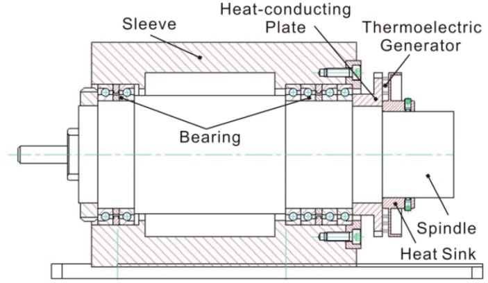
The structure of a thermoelectric generator with a bearing is shown in Figure 1. The heat flow from the spindle bearing is transferred to the thermoelectric generator by a heat-conducting plate, and the generator is mounted on the surface of heat-conducting plate.
Figure 1.
Structure of thermoelectric generator on bearing.
The structure includes thermal and electrical characteristics. Based on this feature, all thermal processes are described in electrical terms using the well-known analogies between electrical and thermal domains, presented in Table 1. According to these analogies, the thermo-electrical behavior of a thermoelectric generator with a bearing can be viewed as an electrical network composed of electrical current sources, voltage sources, resistors and capacitors [19].
Table 1.
Analogies between thermal and electrical variables.
| Thermal Variable | Electrical Variable |
|---|---|
| Heat flow Q (W) | Current flow I (A) |
| Temperature T (K) | Voltage V (V) |
| Thermal resistance Rth (KW−1) | Electrical resistance R (Ω) |
| Thermal mass Cth (JK−1) | Electrical capacity C (F) |
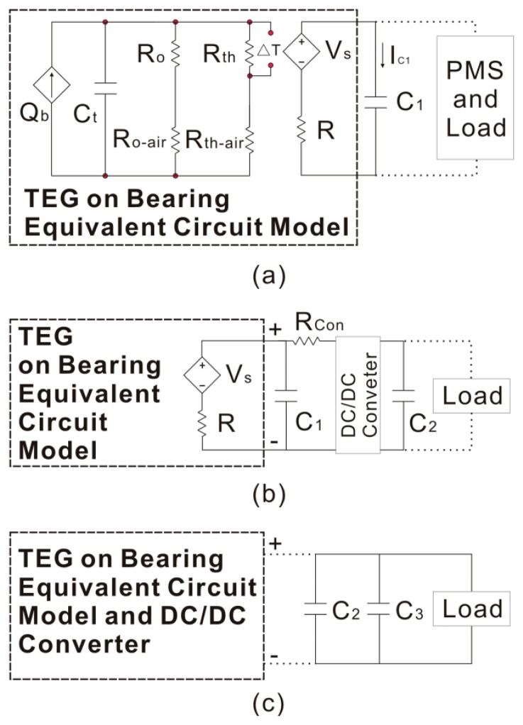
The structure of the bearing includes the shaft, bearing and heat-conducting plate. According to the theory of a thermal network, an equivalent circuit can be built. Combining the thermoelectric generator model, the completed model is shown in Figure 2 [20]. In this model, the output voltage of the thermoelectric generator Vs is viewed as a dependent voltage source, and Vs can be expressed as follows:
| (1) |
where S is the Seebeck coefficient of the thermocouple, Th and Tc are the temperatures at the hot side and cold side respectively. Q̇b. is the heat flow of the bearing, and it can be expressed as [21]:
| (2) |
where M is the friction moment of the bearing, and n is the rotation speed of the spindle. The units for M and n are N·mm and r/min, respectively. Tair is the environmental temperature of the air. Rth is the thermal resistance of the thermoelectric generator, and Ro is the thermal resistance of the metal. Ct is the entire heat capacity of the bearing structure. The thermal resistance between the air and the metal is Ro-air, and the thermal resistance between the air and the generator is Rth-air. R is the internal resistance of the generator, and RL is the load resistance.
Figure 2.
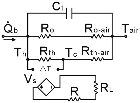
Model of thermoelectric generator with a bearing.
According to this model, the entire structure can be viewed as a power source, and the power depends on the input heat flow Q̇b. The model can be expressed as:
| (3) |
where Q̇ct, Q̇o and Q̇th are the heat flow which goes through Ct, Ro and Rth, respectively. Tc (t) is the temperature difference between the two sides of the heat capacity, Th (t) is the temperature of the TEG hot side, and Tc (t) is the temperature of the TEG cold side. Tc (t), Th (t) and Tc (t) are all functions of time (t). When the time (t) is equal to 0, all the temperatures are Tair. The variables, which depend on the geometric structure of the spindle, are given in Table 2.
Table 2.
Variables used in the model of a thermoelectric generator with a bearing.
| Variable | Value | Unit |
|---|---|---|
| Rth | 3.62 | K/W |
| Rth-air | 3.19 | K/W |
| Ro + Rth-air | 0.14 | K/W |
| R | 27 | Ω |
| RL | 1000 | Ω |
| Ct | 6870 | J/K |
| Q̇b | 301.22 | W |
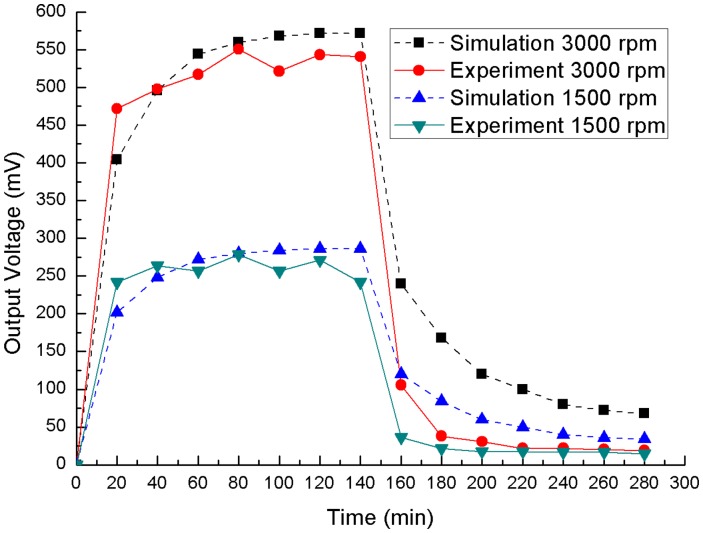
According to this structure and Equation (3), the relationship between the output voltage and time can be simulated in software SPICE, and the simulation is shown in Figure 3. The spindle rotates from 0 min to 140 min, and the speeds are 1500 rpm and 3000 rpm. The experimental output voltage, which is measured under load, is also shown in Figure 3, and the simulation and experiment tests show the same change trends. It can be shown that the voltage usually fluctuates at different speeds, and it is the main reason to charge and discharge the capacitance by time not by voltage. In the experiment, Tair is 293 K, the maximum Th is about 326 K and the maximum Tc is about 304 K.
Figure 3.
Output voltage of simulation and experiment.
2.2. Transformer-Based Power Management System
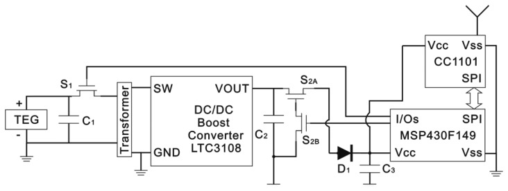
Different power management systems for TEG power harvesting have been studied for intermittent load driving applications such as intermittent wireless transmission of sensed information. A transformer-based power management system, including two super capacitors, is used to harvest microbial fuel cell (MFC) power [22]. Two switches are used in this power management system, and the switches are controlled based on the voltage of the super-capacitors. Unlike the MFC, the TEG, mounted on the heat-conducting plate, cannot supply stable voltage, as shown in Figure 3, so the switches control method is not suitable for the TEG in a spindle unit. A simple improvement is illustrated in this paper, and the power management system is shown in Figure 4. According to this bearing working situation, two switches and a load are operated by a controller. The power management system includes three super-capacitors: the first one is connected to the TEG, the second one is placed after the DC/DC converter, and the last one is installed before the controller. The first super-capacitor (C1) accumulates energy from the TEG and drives the following DC/DC converter. The second super-capacitor (C2), whose capacitance must be confirmed by the target load, saves the power from the converter and drives the load. The last super-capacitor (C3) provides power for the controller, which operates two switches and the load through two input/output (I/O) pins and a serial peripheral interface (SPI) bus, respectively. The first switch (S1) determents the charging and discharging time of the first super-capacitor (C1), and the second switch (S2) controls the charging and discharging time of the second (C2) and third (C3) super-capacitors.
Figure 4.
Schematic diagram of power management system.
2.3. Control Strategy for TEGs on Bearing
The control strategy is shown in Figure 5, and it includes four procedures which are initialization, C1 charging, and C2 charging and load driving. In the initialization procedure, the bearing starts to rotate. In the C1 charging procedure, the switches S1 and S2 must be turned off and the charging time tc1 is dependent on the internal resistance of TEGs. In the C2 charging procedure, S1 is turned on for tc2. After that, if C2 charges for tc3, which is also the operation period time, the procedure of load driving begins.
Figure 5.
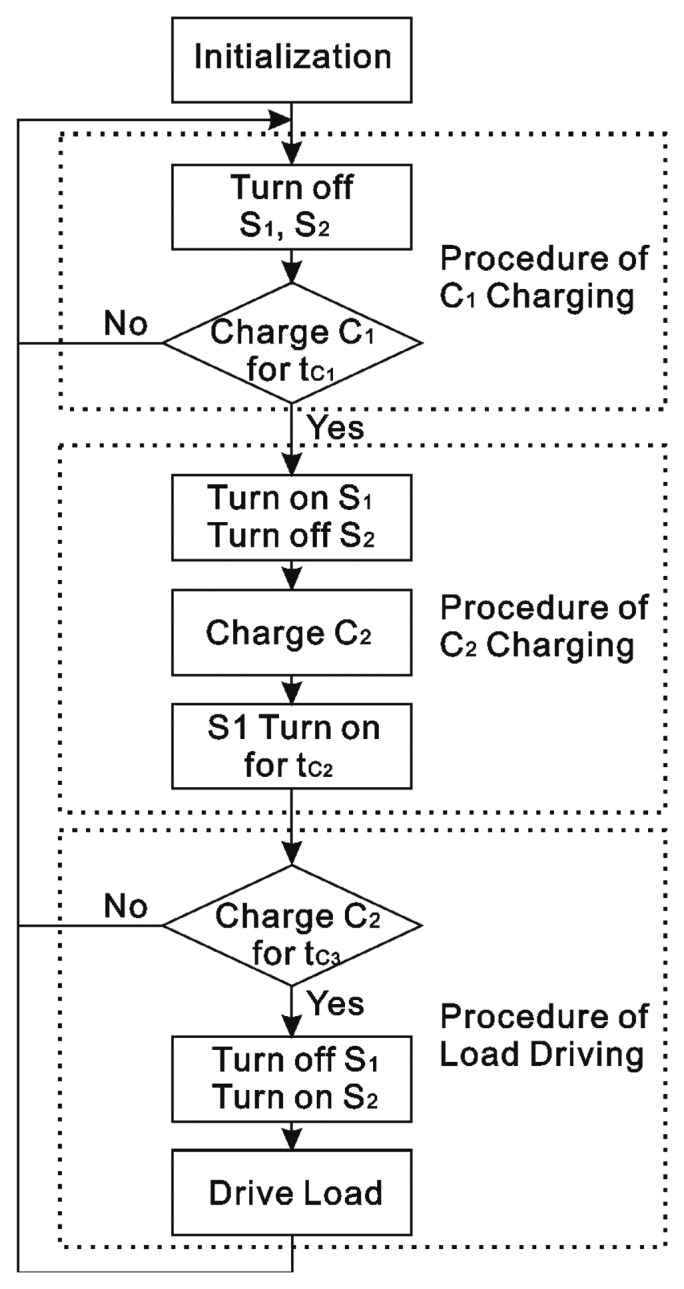
Control strategy for TEGs on bearing.
Equivalent circuit model for TEG on bearing and the overall circuit schematic during C1 charging is shown in Figure 6a.
Figure 6.
Equivalent circuit (a) C1 charging; (b) C2 charging; (c) load driving.
The circuit, containing Vs, C1 and R, can be expressed as:
| (4) |
where IC1 is the current on the electric capacity C1, and UC1(t) is the voltage of the electric capacity C1. According to Equation (4) UC1(t) can be written as follows:
| (5) |
where ΔV is the difference between Vs and the initial voltage UC1(t0). The average power (Pa) stored in the electric capacity C1 during the C1 charging can be expressed as:
| (6) |
Based on Equations (5) and (6) this can be altered as follows:
| (7) |
where ΔV = aVs and b = tC1/RC1 (0 < a < 1, b > 0). Figure 3 shows that Vs is unstable, so the maximum value of Pa should be found at a different Vs. According to Equation (7), the maximum value of Pa only depends on the value of a and b, so that the value of a and b is the key to finding the maximum value at a different Vs. The maximum value of the average power can be found through MATLAB, and it occurs at a = 0.53 and b = 0.08 (ΔV = 0.53Vs and tC1 = 0.08RC1). The optimum values of C1 charging time tC1, the initial voltage UC1(t0) and the final charge voltage UC1(tC1) are 0.08RC1, 0.47Vs and 0.51Vs, respectively. In Figure 6b, the equivalent circuit model for TEG and the overall circuit schematic during C2 charging is shown. According to this circuit, the relationship between the initial voltage UC1(t0) and the final charge voltage UC1(tC1) can be expressed as:
| (8) |
where RCon is the equivalent resistance of the DC/DC converter. According to the value of the initial voltage UC1(t0) and the final charge voltage UC1(tC1), the C2 charging time tC2 can be determined. The equivalent circuit of the load driving procedure is shown in Figure 6c, and the energy changing on C2 and C3 can be expressed as:
| (9) |
where ΔE2 and ΔE3 are the energy changing on C2 and C3, UC2C and UC2D are the voltage of C2 after charging and discharging, UC3C and UC3D are the voltage of C3 after charging and discharging, PController is the power of the controller, tC3 is the period time, ELoad is the energy consumed by the load in one period, UDrive is the minimum drive voltage, UMax_Output is the maximum output voltage of LTC3108 (Linear Technology Corporation, Milpitas, CA, USA). ΔE2 is consumed by charging C3, and ΔE3 is consumed by the controller and load. Because the load runs one time in one period, ELoad is a constant. tC3 is dependent on the frequency of the sending data, and Equation (9) is the conditions of a normal run. When Vs fluctuates during energy harvesting, UC2C and UC3D will change. If UC3D meets the condition of UC3D>UDrive, the power management system can work stably.
3. Simulation and Experimental Evaluation of the Proposed Power Management System
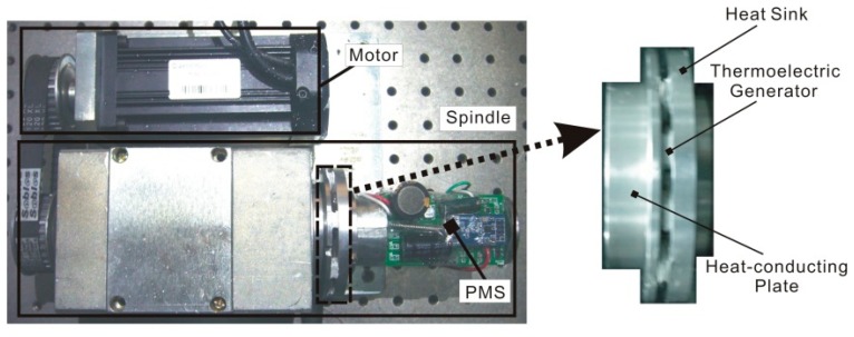
An experimental platform is set up with TEGs, including nine thermoelectric devices, around the spindle, and the volume of the whole platform is about 200 × 200 × 100 mm3 as shown in Figure 7. The TEGs are thermally in parallel but electrically in series. A DC motor (Syntron Company, Beijing, China) is used to control the rotation speed of the spindle through synchronous wheels with 300 W rated power output. The heat flow from the spindle bearing is transferred to the TEGs by a heat-conducting plate. The TEG Xinghe Semiconductor Company, Jiangsu, China; chosen for this study is 8 × 8 × 2.5 mm3 in size with a 2.8 mV/K Seebeck coefficient. Its internal resistance is 3 Ω, and its thermal resistance is 32.6 W/K. The weight of the power management system and the TEGs is approximately 60 g.
Figure 7.
Experimental platform.
As shown in Figure 8, the controller is a MSP430F149 (Texas Instruments, Dallas, TX, USA) and its low-power mode 3 is used in this experiment. The wireless module is a CC1101 (Texas Instruments). S1 is a 1.5 V drive N-channel MOSFET, and its type is a RQ1C075UN (ROHM, Kyoto, Japan). S2, shown in Figure 4b, is composed of S2A and S2B · S2A is a 1.5 V drive P-channel MOSFET, and its type is a RQ1A070ZP (ROHM). S2B is the same as S1 · D1 is used to keep C2 charging C3, and its type is a 1N4007, which has about a 0.5 V voltage drop in the experiment.
Figure 8.
Circuit of power management system.
Before the power management system experiment, some unknown variables should be determined, and they are shown in Table 3. For offering enough response time for S1, choose C1 to 1 F. C2 and C3 is dependent on the load, and they are 1500 μF and 4700 μF, respectively. R, which depends on the thermoelectric device, is equal to 27 Ω. RCon, PController and ELoad can be obtained by the measurement. Because of the voltage drop on D1, UMax_Output is set to 4.1 V.
Table 3.
Variables used in power management system experiment.
| Variable | Value | Unit |
|---|---|---|
| C1 | 1 | F |
| C2 | 1500 | μF |
| C3 | 4700 | μF |
| R | 27 | Ω |
| RCon | 22 | Ω |
| PControllar | 50 | μW |
| ELoad | 0.2 | mJ |
| UDrive | 2.2 | V |
| UMax_Output | 4.1 | V |
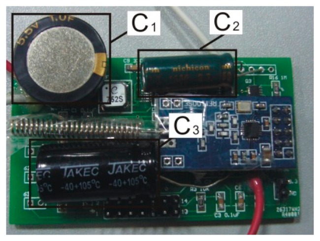
After obtaining those variables, the controlling time can be determined. According to Equation (7), the optimal tC1 is 2 s. After that, tC2 can be calculated through Equation (8), and it is 13 s. tC3 is dependent on the time cycles (TData) of the sending data, and TData = tC3 100 s. Finally, the power management system can be used in this experiment according to those three times, and the photo of the power management system is shown in Figure 9.
Figure 9.
Photo of power management system.
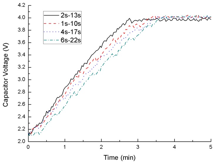
Before putting the power management system on the spindle, a test, using different tC1 to charge C2 from 2.1 V to 4.1 V with 100 mV input, is performed. tC1 is equal to 2 (the optimal value), 1, 4 and 6 s. After that, tC2 can be calculated through Equation (8), and they are 13, 10, 17 and 22 s. The charging mode, using the optimal value, has the higher efficiency than the others as shown in Figure 10. The optimal charging mode can offer more power than others.
Figure 10.
Capacitor voltages of C2.
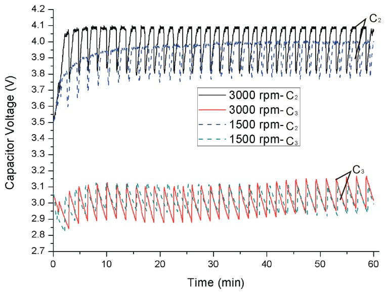
After the test, the power management system is installed on the spindle with the optimal charging set. In the experiment, the spindle rotates at 1500 rpm and 3000 rpm. The voltages of C2 and C3 are shown in Figure 11. At the beginning C2 and C3 are charged to 3.5 V and 3 V respectively, and then the spindle will start rotating. At 3000 rpm, the voltage of C2 jumps to 4.1 V and fluctuates between 3.8 V and 4.1 V. At 1500 rpm, the voltage of C2 rises to 3.8 V and fluctuates between 3.6 and 3.9 V, and the voltage of C2 also has a rising trend. This phenomenon is caused by the different speeds. As shown in Figure 3, the higher speed can produce higher output voltage, so the voltage of C2 can reach to 4.1 V at 3000 rpm.
Figure 11.
Capacitor voltages of C2 and C3.
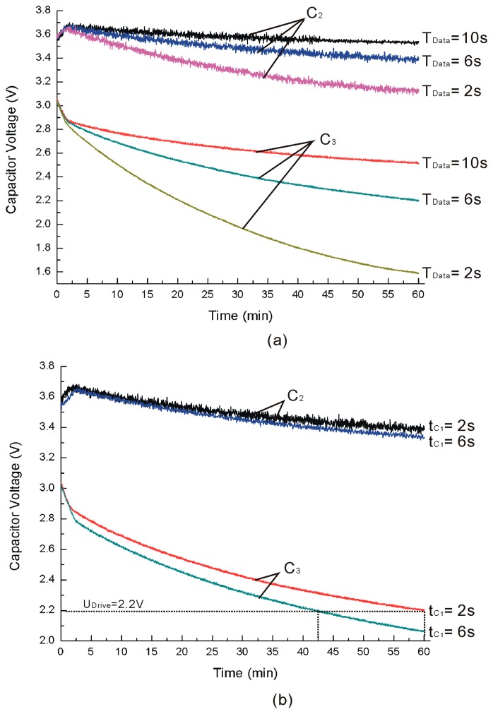
For analyzing the power management system working at different sampling cycles of the wireless sensor, the time cycles (TData), which are equal to tC3, are set as 2, 6 and 10 s with tC1 equal to 2 s and rotating at 1500 rpm, and the voltages of C2 and C3 are shown in Figure 12a. Because TData is small, the voltages of C2 and C3 do not fluctuate like those shown in Figure 11. It is clear that TData is so small the voltages of C2 and C3 cannot be held on a stable voltage, and the voltages decrease quickly with TData reducing. This phenomenon can also be explained by Equation (9). With TData reducing, the power consumption increases and Equation (9) cannot be satisfied. Different tC1 with TData equal to 6 s are shown in Figure 12b. The voltages of C2 and C3 using the optimal tC1 decrease slower than those not using the optimal value, and it is the same as shown in Figure 11. It is clear that the voltages of C3 will be below 2.2 V (UDrive) with tC1=6 s and the wireless sensor cannot work stably under such low voltage settings. Using the optimal tC1=2 s, the voltages of C3 can be kept higher than UDrive for 60 min. On the other hand, the voltages of C3 can be kept higher than UDrive for 42.5 min when using tC1=6 s and tC2=17 s. That is to say, the optimal tC1 can increase by a 41.2% stable working time when compared with tC1=6 s. Similar results are measured for other comparative experiments between tC1=2 s and other values. As the sampling cycle time of the wireless sensor is longer, the wireless sensor works more stably.
Figure 12.
Capacitor voltages of C2 and C3. (a) Different time cycles; (b) Different tC1.
4. Conclusions
While the power generating capacity of TEGs can be improved in terms of using different thermoelectric materials and/or choosing different heat exchange structures, a power management system is always essential to enhance the energy harvesting and usage efficiency. This study presents a transformer-based power management system and its control strategy is to make the wireless sensor work stably at different speeds. Because the output of the TEG varies with the speed of the spindle, the strategy uses charging/discharging time of the capacitors instead of the voltage to control energy harvesting. The proposed power management system is installed on a spindle to test its working state at different speeds. The experiments show that the optimal time can offer more power than other times, and it is also found that the power management system can drive the wireless sensor very well when the sampling cycle time of the sensor is relatively long. The results also show that the small sampling cycle time (TData) will induce the power management system to work unstably. However, the optimal tC1 of the power management system still improves the performance of TEG under several-seconds during sampling cycles and increases to a 41.2% stable working duration compared with tC1=6 s under TData = 6 s. The findings prove that the optimal time shown in this paper can make the power management system have longer work times when compared with other systems during the same cycle times.
Acknowledgments
This work is supported by the National Natural Science Foundation of China (No. 51105336) and the National Natural Science Foundation of China (No. 61100101).
Author Contributions
Sheng Li: Conception, design and acquisition of data; Xinhua Yao: Analysis and interpretation of data, and participate in revising the article; Jianzhong Fu: Conception of overall study.
Conflicts of Interest
The authors declare no conflicts of interest.
References
- 1.Hudak N.S., Amatucci G.G. Small-scale energy harvesting through thermoelectric, vibration, and radiofrequency power conversion. J. Appl. Phys. 2008;103:24. [Google Scholar]
- 2.Marian V., Allard B., Vollaire C., Verdier J. Strategy for Microwave Energy Harvesting from Ambient Field or a Feeding Source. IEEE Trans. Power Electron. 2012;27:4481–4491. [Google Scholar]
- 3.Szarka G.D., Stark B.H., Burrow S.G. Review of Power Conditioning for Kinetic Energy Harvesting Systems. IEEE Trans. Power Electron. 2012;27:803–815. [Google Scholar]
- 4.Zhang D., Yang F., Shimotori T., Wang K.-C., Huang Y. Performance evaluation of power management systems in microbial fuel cell-based energy harvesting applications for driving small electronic devices. J. Power Sources. 2012;217:65–71. [Google Scholar]
- 5.Dallago E., Danioni A., Marchesi M., Venchi G. An Autonomous Power Supply System Supporting Low-Power Wireless Sensors. IEEE Trans. Power Electron. 2012;27:4272–4280. [Google Scholar]
- 6.Roundy S., Wright P.K., Rabaey J.M. Energy Scavenging for Wireless Sensor Networks: With Special Focus on Vibrations. Kluwer Academic; Boston, MA, USA: 2004. [Google Scholar]
- 7.Tan Y.K., Panda S.K. Optimized Wind Energy Harvesting System Using Resistance Emulator and Active Rectifier for Wireless Sensor Nodes. IEEE Trans. Power Electron. 2011;26:38–50. [Google Scholar]
- 8.Eakburanawat J., Boonyaroonate I. Development of a thermoelectric battery-charger with microcontroller-based maximum power point tracking technique. Appl. Energy. 2005;83:687–704. [Google Scholar]
- 9.Jin X., Lee C., Feng H. Fabrication, and Characterization of CMOS MEMS-Based Thermoelectric Power Generators. J. Microelectromech. Syst. 2010;19:317–324. [Google Scholar]
- 10.Rowe D.M. Thermoelectrics Handbook: Macro to Nano. CRC Press; Boca Raton, FL, USA: 2006. [Google Scholar]
- 11.Sungkyu Cho N.K., Park S., Kim S. A Coreless Maximum Power Point Tracking Circuit of Thermoelectric Generators for Battery Charging Systems. Proceedings of the IEEE Asian Solid-State Circuits Conference; Beijing, China. 8–10 November 2010; p. 4. [Google Scholar]
- 12.Donovan C., Dewan A., Heo D., Beyenal H. Batteryless, Wireless Sensor Powered by a Sediment Microbial Fuel Cell. Environ. Sci. Technol. 2008;42:8591–8596. doi: 10.1021/es801763g. [DOI] [PubMed] [Google Scholar]
- 13.Guan M.J., Liao W.H. On the efficiencies of piezoelectric energy harvesting circuits towards storage device voltages. Smart Mater. Struct. 2007;16:498. [Google Scholar]
- 14.Meehan A., Hongwei G., Lewandowski Z. Energy Harvesting with Microbial Fuel Cell and Power Management System. IEEE Trans. Power Electron. 2011;26:176–181. [Google Scholar]
- 15.Shantaram A., Beyenal H., Veluchamy R.R.A., Lewandowski Z. Wireless Sensors Powered by Microbial Fuel Cells. Environ. Sci. Technol. 2005;39:5037–5042. doi: 10.1021/es0480668. [DOI] [PubMed] [Google Scholar]
- 16.Vullers R.J.M., van Schaijk R., Doms I., van Hoof C., Mertens R. Micropower energy harvesting. Solid-State Electron. 2009;53:684–693. [Google Scholar]
- 17.Dewan A., Donovan C., Heo D., Beyenal H. Evaluating the performance of microbial fuel cells powering electronic devices. J. Power Sources. 2010;195:90–96. [Google Scholar]
- 18.Peretz M.M., Ben-Yaakov S. A heuristic digital control method for optimal capacitor charging. Proceedings of the IEEE Energy Conversion Congress and Exposition (ECCE 2009); San Jose, CA, USA. 20–24 September 2009; pp. 1118–1125. [Google Scholar]
- 19.Mitrani D., Salazar J., Turo A., Garca M.J., Chavez J.A. One-dimensional modeling of TE devices considering temperature-dependent parameters using SPICE. Microelectron. J. 2009;40:1398–1405. [Google Scholar]
- 20.Li S., Yao X., Fu J. Power output characterization assessment of thermoelectric generation in machine spindles for wireless sensor driving. Sens. Rev. 2014;34:192–200. [Google Scholar]
- 21.Harris T.A., Kotzalas M.N. Essential Concepts of Bearing Technology. CRC Press; New York, NY, USA: 2007. [Google Scholar]
- 22.Yang F., Zhang D., Shimotori T., Wang K.-C., Huang Y. Study of transformer-based power management system and its performance optimization for microbial fuel cells. J. Power Sources. 2012;205:86–92. [Google Scholar]


