Abstract
We present the modeling efforts on antenna design and frequency selection to monitor brain temperature during prolonged surgery using non-invasive microwave radiometry. A tapered log-spiral antenna design is chosen for its wideband characteristics that allow higher power collection from deep brain. Parametric analysis with HFSS is used to optimize antenna performance for deep brain temperature sensing. Radiometric antenna efficiency (η) is evaluated in terms of the ratio of power collected from brain to total power received by the antenna. Anatomical information extracted from several adult computed tomography (CT) scans is used to establish design parameters for constructing an accurate layered 3D tissue phantom. This head phantom includes separate brain and scalp regions, with tissue equivalent liquids circulating at independent temperatures on either side of an intact skull. The optimized frequency band is 1.1–1.6 GHz producing an average antenna efficiency of 50.3% from a 2 turn log-spiral antenna. The entire sensor package is contained in a lightweight and low profile 2.8 cm diameter by 1.5 cm high assembly that can be held in place over the skin with an electromagnetic interference (EMI) shielding adhesive patch. The calculated radiometric equivalent brain temperature tracks within 0.4°C of measured brain phantom temperature when the brain phantom is lowered 10°C and then returned to original temperature (37°C) over a 4.6-hour experiment. The numerical and experimental results demonstrate that the optimized 2.5 cm log-spiral antenna is well suited for the non-invasive radiometric sensing of deep brain temperature.
Index Terms: Antenna design, brain temperature, log-spiral antenna, microwave radiometry, noninvasive monitoring
I. Introduction
Prolonged surgeries use general anesthesia that impairs thermoregulation processes in the human body and is associated with hypothermia, i.e., when core temperature is below 36°C [1]. In some surgeries hypothermia is actually forced; patients are cooled 5–18°C below normal body temperature in order to reduce sensitivity of critical brain tissues to ischemia [2]. In either case it is critical to safely and rapidly rewarm the patient to normal body core temperature (37°C) before the end of surgery to avoid complications such as a higher risk of morbid myocardial outcomes or prolonged surgical recovery [1–4]. Current thermometry devices typically measure surface temperatures or intracavitary surrogates of body temperature that do not accurately reflect true core temperature of deep organs. Each of these core temperature surrogates have inherent problems with probe placement, time delay in readings, and/or are objectionably invasive [5, 6]. In this paper we present a novel monitoring approach based on non-invasive and entirely passive microwave (MW) radiometry. We choose to monitor core temperature inside the brain rather than in alternative sites due to the critical nature of this organ and its central role in thermoregulation [2, 7, 8].
Microwave radiometry is a non-invasive technique that collects thermal radiation (electromagnetic noise) emitted in the MW frequency spectrum by any material above absolute zero temperature. The thermal radiation is received by an antenna and converted, with proper calibration, into a measure of absolute temperature taken from a weighted average of its radiation pattern [9–11]. This technique contrasts with infrared thermometry that collects thermal radiation at higher frequencies (0.3–430 THz), where photons travel only a few millimeters through skin.
There have been many reports of medical applications of MW radiometry, including the detection of breast cancer [12], monitoring and control of superficial and deep hyperthermia applicators [13–15], measurement of brain temperature in infants [9] or adults [16], vesicoureteral reflux detection in young children [17, 18] and more recently monitoring of brown fat metabolism [19]. In the particular case of monitoring adult brain temperature, there are no reports to our knowledge of an antenna that is small enough to conform to the human head during prolonged surgery; present a stable reading over several hours; and offer an accuracy below 0.5°C, which is the smallest difference that has been associated with hypothermia-induced complications [7].
The major challenge in MW radiometry lies in the nature of thermal noise itself which is characterized by extremely low power levels (~10−14 W/MHz at 37°C). To maximize power collection, wideband antennas are generally used to collect thermal noise over a wide frequency range. We previously demonstrated that due to its circular polarization and wide band matching, a 7 cm diameter log-spiral antenna is sensitive to small temperature variations in deep-seated targets [17]. Thus, we choose the same log-spiral design for our new compact radiometric sensor, but in order to be conformal with the human head we use a diameter of 2.5 cm.
In this paper we focus on the theoretical modeling of the design of a miniature 2.5 cm diameter receive antenna and optimization of the frequency band for radiometric temperature monitoring of brain. A realistic head phantom model is built to validate the theory and demonstrate performance of this sensor.
II. MATERIAL AND METHODS
A. Log-spiral antenna design
Log-spiral antennas exhibit frequency-independent properties over a wide band limited by the finite physical dimensions of the antenna [20, 21]. The microstrip log-spiral design explored in this work consists of a single arm with variable width metal trace formed by ρe0 (inner) and ρe1 (outer), defined by:
| (1) |
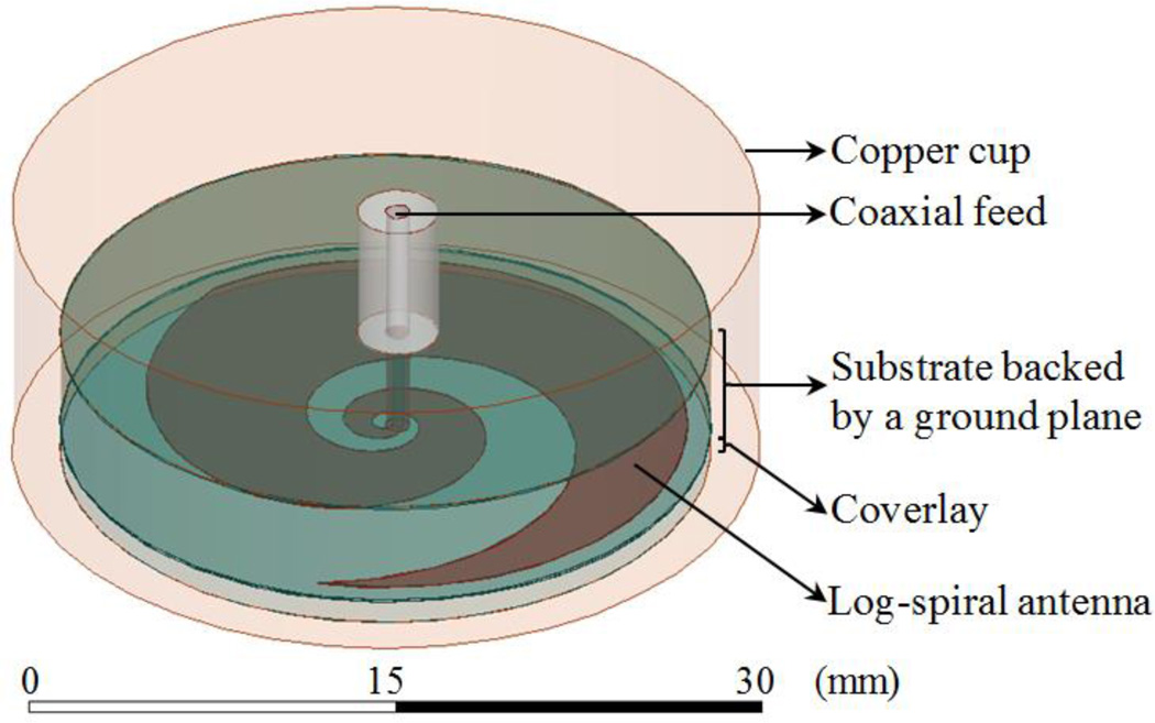
where (ρ, θ) are polar coordinates; ρ0 = 0.25 mm and ρ1 = 0.75 mm are the initial (θ = 0) inner and outer radius of the metal trace, respectively, located at the center of a coaxial feed port with diameter ρ1 − ρ0; a is the spiral growth rate coefficient given by a = ln(ρext/ρ0)/(2πN), which is defined by the number of log-spiral turns (N) possible within an outer radius (ρext). The antenna diameter is fixed at 2.5 cm to allow the sensor to be conformal with the human head. The end of the spiral arm is tapered (see Fig. 1) to minimize reflections at lower frequencies and improve impedance matching [21].
Fig. 1.
Radiometric receive antenna: microstrip log-spiral patch design with tapered ends.
Since the function of the antenna is to collect thermal radiation, which is randomly polarized, it is desirable for the antenna to have circular or elliptical rather than linear polarization. When the antenna arm length is shorter than one wavelength, polarization is linear. As the arm length is increased (or frequency increased) the polarization becomes non-linear [20]. To be an efficient radiator, the spiral length must be at least similar to the wavelength. Thus, the number of turns is a parameter to be optimized. The arm length L(N) is determined over the line defined by ρe0 and is given by:
| (2) |
The microstrip is mounted on a 4.45 mm thick hydrocarbon ceramic substrate that is backed by a ground plane (Fig. 1). Three different substrates are chosen from the RO3000© series (Rogers Corp., USA) due to availability, ease of construction, high dielectric permittivity, and ultralow loss properties (see Table I), all of which are desirable for radiometric applications.
Table I.
Ceramic substrates used in the antenna design
| Substrate | Permittivity εr | Conductivity σ (S/m) |
|---|---|---|
| RO3003© | 3.00 | 2.93 × 10⁻⁴ |
| RO3006© | 6.15 | 9.23 × 10⁻⁴ |
| RO3010© | 10.20 | 1.68 × 10⁻³ |
The presence of a very thick and high dielectric substrate behind the antenna will affect the antenna’s operating bandwidth. According to the ring theory [22], the lower cutoff frequency fL is a function of the circumference length with radius ρext and the higher cut-off frequency fH is dependent on the diameter of the coaxial feed port (ρ1 − ρ0):
| (3) |
where c is the speed of light and εr,eff is effective permittivity, which affects the wavelengths detected by the antenna.
The final element of the antenna is a thin coverlay disk (radius ρext) placed between the spiral metal trace and scalp (Fig. 1), which is used to improve antenna match impedance to tissue and provide electrical insulation of the metal from the conductive skin. The coverlay is chosen from the ultralow loss (σcoverlay = 4.50×10⁻³ S/m) Eccostock® HiK series (Emmerson & Cumming, Randolph, MA, USA) with thickness (δ) and dielectric permittivity to be optimized (Table II).
Table II.
Log-spiral antenna parameters for parametric analysis
| Property | Parametric analysis |
|---|---|
| Coverlay permittivity εr, coverlay | 5–40 with step = 5 |
| Log-spiral turns N | 0.25–2.75 with step = 0.25 |
| Coverlay thickness δ (mm) | 0–5 mm with step = 1 mm |
B. Experimental human head phantom model
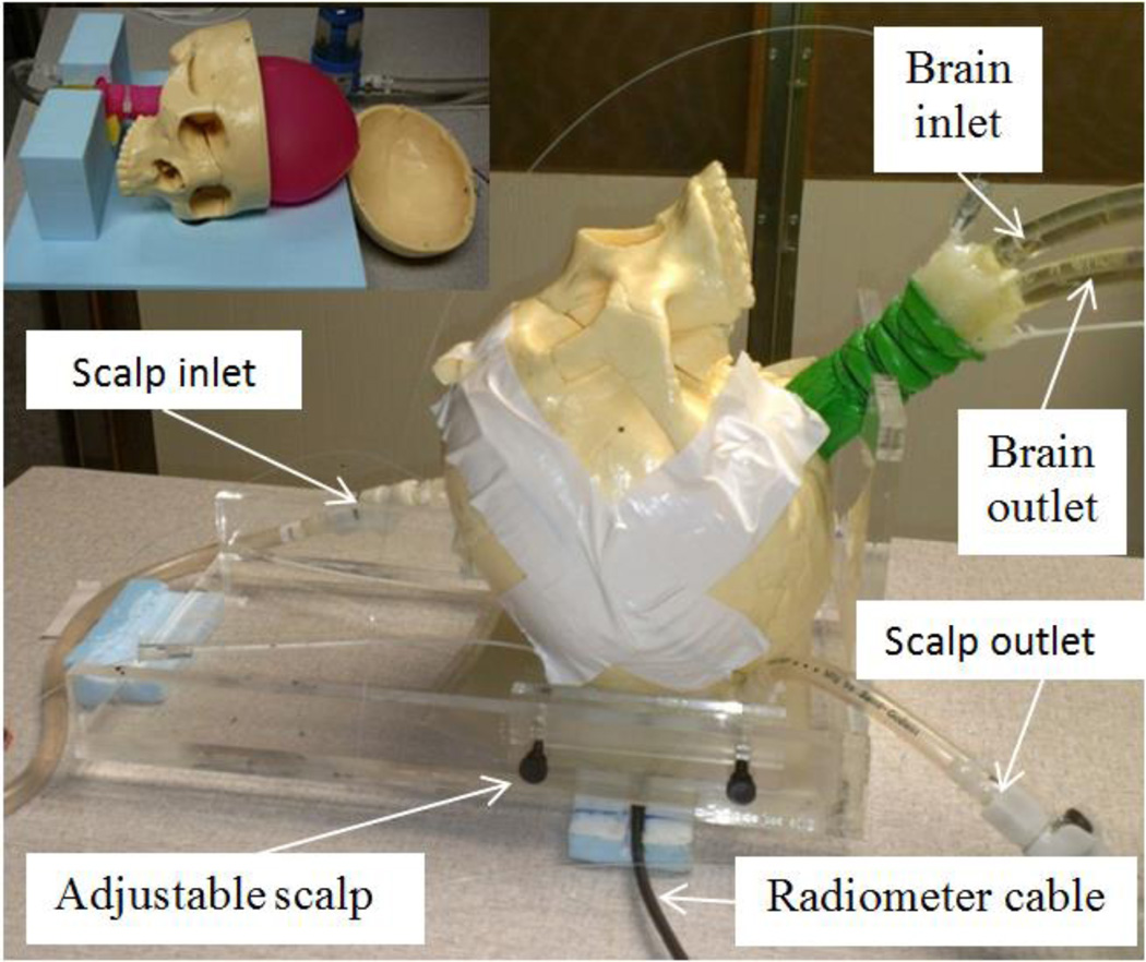
A physical head phantom was developed to validate the optimized antenna design. From computed tomography (CT) scans of an unidentified patient head, we determined appropriate values for the thickness of scalp, bone, and brain tissues to generate a realistic physical model. Measurements showed that scalp thickness varies from 4.2 mm (forehead) to 8 mm (temporal lobe), and the average thickness of skull bone is 6.7 mm in both regions. Based on these dimensions, an experimental model of the human head was constructed (Fig. 2) around an artificial human skull (Life Size Skull, www.anatomywarehouse.com).
Fig. 2.
Human head model with variable temperature liquid brain phantom. This liquid circulates through a balloon that fills the inside of the skull. The liquid scalp phantom is also temperature controlled and circulates in an adjustable thickness region under the skull. The black coaxial cable connects the radiometer electronics to the antenna sensor coupled to scalp surface.
To model the thermodynamics of scalp, an adjustable thickness (6–16 mm) compartment filled with circulating temperature-controlled distilled water was sealed against the outer surface of the skull. A mixture of propylene glycol (46%) and deionized water (54%) was used to approximate the electrical properties of mixed grey and white matter. The brain liquid phantom was circulated vigorously (1.7 liter/min) with a high flow peristaltic pump (Masterflex 7592-40, Cole Parmer, Vernon Hills, IL, USA) through a water bath heater (Neslab RTE740, Cole Parmer) and into a latex balloon (Fig. 2 top left) that filled the interior of the skull. Scalp temperature was circulated similarly, but controlled in a different water bath to allow independent scalp and brain temperatures and thus obtain realistic differential temperature of surface and deep tissues.
Electrical properties for the liquid tissue phantoms were characterized at normothermic temperatures for scalp (32°C) and brain (37°C) using a coaxial dielectric probe (E85070C, Agilent Technologies, Santa Rosa CA) connected to a network analyzer (E5071C, Agilent Technologies).
C. Virtual human head computational model
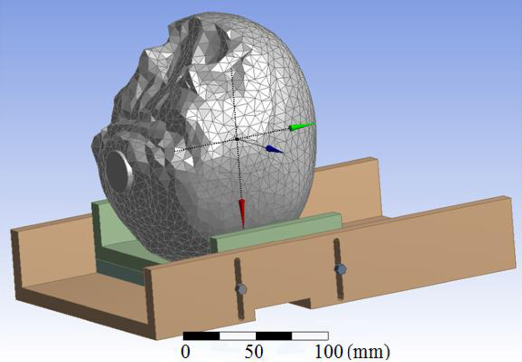
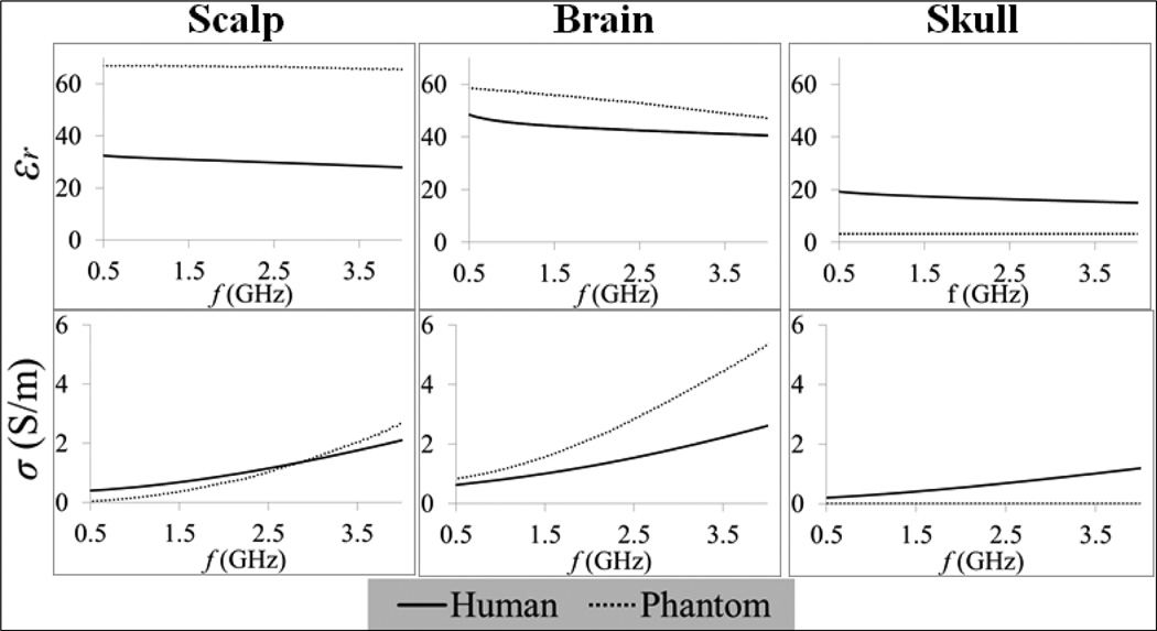
The physical head phantom was translated into an anatomically accurate computer-aid design model (Fig. 3). CT images of the artificial skull were acquired and segmented using Avizo (Visualization Sciences Group, Burlington, MA). The resulting 3D surfaces of the surrogate skull were assumed to be the outer boundary of a uniform volume of tissue. The remaining objects were created in DesignModeler (Ansys Inc., Canonsburg, PA) with accurate geometry and dimensions. The final virtual phantom model was then imported into HFSS (Ansys Inc., Canonsburg, PA) and coupled with the antenna design to perform a finite element method simulation-based optimization. This computational approach has been validated experimentally for similar antenna design projects [18, 19]. Note that the phantom frequency dependent properties were integrated in this dispersive numerical model (Fig. 4).
Fig. 3.
Computational model of the multilayer human head phantom used for antenna optimization.
Fig. 4.
Frequency dependent electrical properties (relative permittivity εr and electrical conductivity σ) of both phantom models (measured here) and human tissues [23].
D. Optimization goals
The reciprocity theorem states that the radiation and receiving patterns of an antenna are identical [10]. Thus one can estimate the radiation receiving pattern from the power loss density profile Pd (W/m3) that is given by:
| (4) |
where E (V/m) is the electric field at the position r in the computational domain V. The antenna efficiency η is evaluated in terms of Pd and is defined by the ratio of power received from brain to total power received by the antenna:
| (5) |
The design optimization is based on a parametric analysis (Table II) that aims to maximize efficiency as well as bandwidth (Δf) of the receive antenna (Table III). The band is chosen based on the constraint S11 ≤ −10 dB, in order to minimize the mismatch (S11) between antenna and tissue load. For convenience we define ηΔf as the average efficiency over Δf where S11 ≤ −10 dB. This function (ηΔf) is used to quantitatively compare simulation results of the different parametric analyses. Furthermore, due to the frequency allocation for wireless local area networks, mobile phones, and pagers, by the Federal Communications Commission (FCC), some frequency bands must be avoided due to excessive environmental background interference (Table III).
Table III.
Log-spiral antenna goal functions and constraints
| Function | Goal/Constraints |
|---|---|
| Efficiency η | Maximization |
| Bandwith Δf | Maximization |
| S11 | ≤ −10 dB |
| FCC allocated frequencies | 0.81–0.96, 1.71–1.99, and 2.4–2.5 GHz |
E. Radiometric temperature measurements
Following the design optimization, the antenna was fabricated, connected to the radiometer electronics described elsewhere [11, 24, 25] and tested on the physical phantom. The radiometer used is an analog Dicke radiometer that uses a dual-matched ultralow noise and high gain (G) amplifier design to provide a time sequenced comparison to an internal 50 ohm reference for long-term stable calibration. Radiometric power (Pant) was measured continuously and converted into an equivalent temperature (TB) using:
| (6) |
where kB is the Boltzmann constant. Volume averaged brain temperature (Tbrain) was extracted from TB using an algorithm similar to those described previously [9–11, 14] and modified for this application by Maccarini et al. [25]:
| (7) |
where αi (i = 1,2) are calibration coefficients determined from a calibration measurement and equation (6); Tref is the temperature of the 50 ohm calibration reference that is being monitored with a thermistor located in the printed circuit board. This reference temperature allows to derive the gain in equation (6) since the amplifiers of the reference and antenna are matched, yielding Pref = GkBTrefΔf.
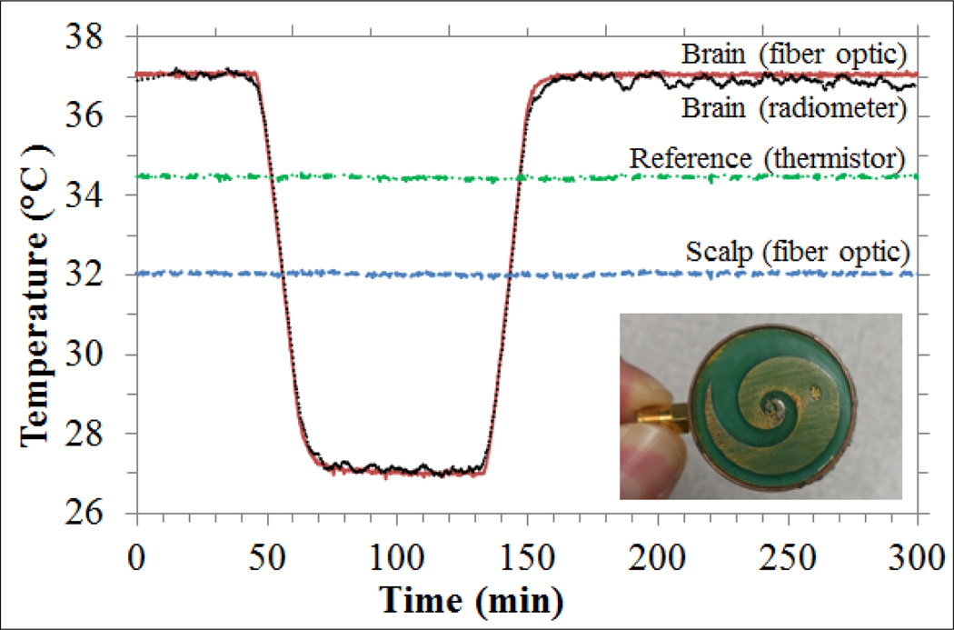
An initial steady state condition was established in the head physical model by circulating the scalp phantom at 32°C and brain phantom at 37°C. Temperature in the brain phantom was cycled between the values 37-27-37°C to simulate the induction of hypothermia during surgery. The heating water bath for the scalp phantom was held constant to provide constant scalp temperature and thus ensuring radiometric reading variations independent from scalp. All phantom temperatures were monitored continuously using fiber optic probes (Luxtron 3100, LumaSense Technologies, Santa Clara, CA) for comparison with the radiometric readings.
III. Results and Discussion
A. Antenna bandwidth simulations
Simulations of S11 and efficiency (η) showed no significant dependence on coverlay permittivity over the range 5–40; thus simulations were performed using εr,coverlay = 30 due to availability. For the initial optimization of εr,substrate, simulations used δ = 1 mm since that parameter as found to be less critical than εr,substrate and number of turns N [18]. After determining optimal εr,substrate and N, a parametric analysis for δ was implemented in order to refine the results.
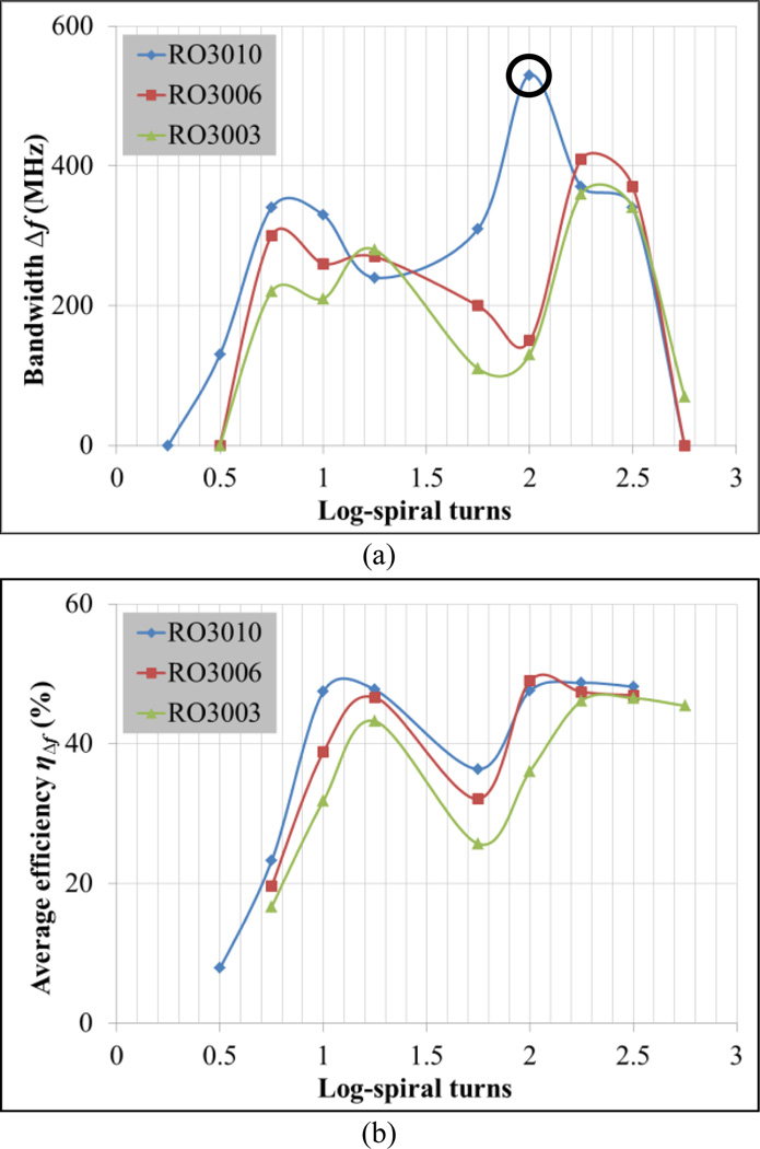
Fig. 5a presents operating bandwidth Δf for which S11 ≤ −10 dB and compares simulation results for three substrates (Table I). Best results are achieved for substrate RO3010 with N = 2, which provides an ultra-wideband of approximately 500 MHz. Fig. 5b presents average antenna efficiency across the band (ηΔf), showing similar efficiencies for RO3010 and RO3006 substrates for most values of N and generally higher efficiency with increasing substrate permittivity. Due to the combination of high efficiency and large bandwidth, εr,substrate = 10.2 (RO3010) and N = 2 are chosen as nominal values for the remaining simulations.
Fig. 5.
Determination of operating frequency bandwidth Δf where S11 ≤ −10 dB for substrates RO3010 (εr,substrate = 10.2), RO3006 (εr,substrate = 6.15) and RO3003 (εr,substrate = 3): a) Δf vs. log-spiral turns N, and b) average antenna efficiency ηΔf vs. N. Nominal values: δ = 1 mm and εr,coverlay = 30.
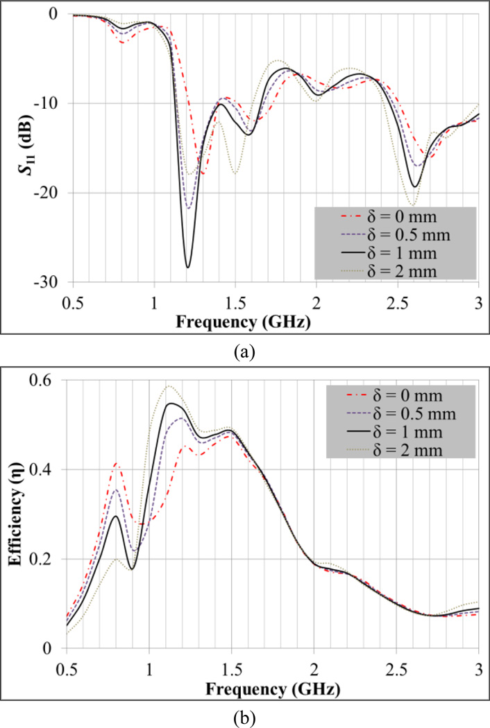
The use of a coverlay improves both the matching impedance and antenna efficiency (Fig. 6). Best results for S11 and efficiency are achieved for δ = 1 mm (Fig. 6a) yielding an average efficiency ηΔf of 50.3% in the 1.1–1.6 GHz band (Fig. 6b). Note that the difference between the higher and lower frequencies of this band corresponds to the Δf highlighted with a circle in Fig. 5a. Antenna efficiency results are only presented for the coverlay thickness parametric analysis since it does not vary significantly in the remaining variables’ sweeps. In fact, the efficiency is higher than 40% across the band where S11 ≤ −10 dB for all simulations, with the exception of the zero thickness coverlay (Fig. 6b).
Fig. 6.
Coverlay thickness (δ) parametric analysis to improve impedance matching at the interface between antenna and human head. a) S11 vs. frequency and b) antenna efficiency vs. frequency. Nominal values: N = 2, εr,coverlay = 30 and εr,substrate = 10.2.
B. Simulated radiation patterns
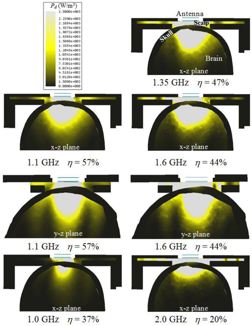
Fig. 7 shows the power loss density Pd (W/m3) of the optimized tapered log-spiral antenna for five representative frequencies. Within the range 1.1–1.6 GHz, simulations demonstrate that a significant portion of the microwave energy is received from deep brain. As expected, there is little power deposited in (or received from) the phantom bone due to its very low electrical conductivity (Fig. 4). Below 1.0 GHz the antenna exhibits lower efficiency due to its small size compared to the wavelength, though this improves immunity from EMI at the particularly noisy 810–960 MHz band. At higher frequencies approaching 2.0 GHz, energy received by the antenna is collected mainly from the scalp.
Fig. 7.
HFSS-simulated receive pattern for the 2.5 cm log-spiral antenna when placed on the heterogeneous multilayer human head model. The receive pattern is shown for five specific radiometric sensing frequencies, i.e., 1.0, 1.1, 1.35, 1.6 and 2.0 GHz. Radiometric antenna efficiency η (%) is evaluated in terms of the ratio of the power collected from brain to the total power received by the antenna and thus intrinsically normalized.
The lower cut-off frequency fL can be extrapolated from Fig. 6a and corresponds to the frequency where S11 starts decreasing abruptly: fL = 0.98 GHz. From equation (3) we can deduce εr,eff = 15.2, which is slightly higher than εr,substrate = 10.2. The higher effective permittivity occurs since it also accounts for higher scalp and brain phantom permittivities (Fig. 4), e.g., εr,scalp = 67.0 and εr,brain = 59.0 at 1.35 GHz. These results indicate that the substrate dictates the wavelength attenuation of the electromagnetic waves that are detected by the spiral antenna. Using εr,eff = 15.2 one can estimate the detectable wavelengths by the spiral antenna to be in the interval 48.1–70.0 mm along the bandwidth 1.1–1.6 GHz. These values are higher but of the same order than the spiral length 41.2 mm (N = 2). The radiation patterns on Fig. 7 (x–z and y–z planes) for the lower (1.1 GHz) and upper (1.6 GHz) frequencies of the operating band show a slightly more focused radiation pattern in the y–z plane which indicates an elliptical polarization.
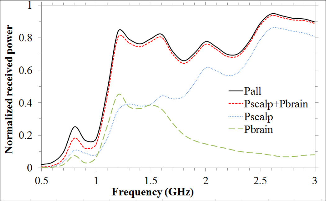
Fig. 8 presents HFSS simulations of absolute power collected from different regions of the head model as a function of frequency. One can observe that the antenna receives energy mainly from scalp and brain in the 1.1–1.6 GHz band and mainly from scalp at higher frequencies. The remaining energy is collected from skull (<0.3 %), mylar and plexiglass used to support the head phantom (<1.5 %), and the antenna materials including substrate and coverlay (<2.3 %).
Fig. 8.
Normalized received power vs. frequency: from brain (Pbrain), scalp (Pscalp), sum of power received from scalp and brain (Pscalp+Pbrain), and from the entire computational volume composed of air, scalp, skull, brain and head model plexiglass support structure (Pall).
C. Antenna implementation and phantom results
A radiometer sensor was built according to the optimized parameters (bottom right in Fig. 9). The sensor package is lightweight and has a low profile of 2.8 cm diameter by 1.5 cm height. This sensor can be held in place on the scalp with an EMI shielding adhesive patch and/or elastic strap. The sensor was tested in a realistic head phantom experiment that simulates brain temperature variations over a 4.6-hour surgery. Radiometric brain temperature (Tbrain) was determined using equations (6) and (7) with α1 = 0.32, which was determined from an initial calibration measurement (Tbrain = 37°C at t = 0 s). The α coefficients are, in theory, closely related to the average thermal radiation contribution from each region over the band 1.1–1.6 GHz. For instance, one could expect α1 ≈ 0.5 since in brain ηΔf ≈ 50%, but in practice the radiometer system components also contribute with thermal radiation, which reduces the overall contribution from phantom materials. From simulations, the energy collection is mostly from scalp and brain. Equation (7) accounts for brain temperature explicitly, whereas scalp temperature is embodied in Tref since the high thermal conductivity (> 1 W/m/K) of both coverlay and substrate materials allow high heat transfer between scalp substrate, where the thermistor is located. This is clearly illustrated in Fig. 9, since Tref is dictated by Tscalp plus 2.4°C due to electronic heating.
Fig. 9.
Effective brain temperature derived from total power measurements of the non-invasive radiometric sensor (black curve) closely mirrors the actual temperature of the circulating brain phantom (red curve). Green curve (dash dot line) shows reference temperature and blue curve (dash line) shows the measured scalp temperature, with no significant drift during the 4.5 hour period of monitoring. Bottom right - photo of a 2.5 cm diameter log-spiral antenna encapsulated together with radiometer printed circuit inside a cylindrical copper tube with 1 mm wall thickness and 1.5 cm height.
The scalp phantom was maintained constant at 32°C to demonstrate clearly that the radiometric power changes were due entirely to intracranial temperature variation. However, during surgery all tissues reduce their temperature due to anesthesia. The next step will be to vary scalp phantom temperature as well, to account for all possible temperature distribution scenarios during surgery. This will imply to refine the calibration algorithm by including explicitly scalp temperature in equation (7) as “α3Tscalp”, which will be measured with a thermistor at the skin surface. This setup will allow to correlate α parameters (equation (7)) with simulated average efficiencies (ηΔf) and thus isolating the thermal noise contribution of the radiometric system.
The maximum difference between the temperature measured directly with fiber optic sensors and the calculated equivalent radiometric brain temperature was 0.38°C during the rapid temperature changes when cooling (−0.35°C/min) and rewarming (0.32°C/min) the brain phantom (Fig. 9). This occurs due to the 74 s delay in measurements caused by a moving median calculation to reduce EMI. However, the temperature rates of patients undergoing surgery are at least 10 times slower than the cooling/rewarming rates implemented in our study [7]. Thus, the transient temperature errors during rapid cooling and rewarming periods appear to overestimate the errors of slowly changing temperatures. Moreover, these temperature errors should be lower than the errors from reading core temperature from slowly changing sites like esophagus and rectum. The 0.4°C experimental error fits the current clinical need of ≤0.5°C resolution, corresponding to the smallest temperature difference that has been associated with hypothermia-induced complications [7]. The data also demonstrate our ability to track temperature changes of brain (core temperature) during long time periods typical of open heart bypass surgery, enabling the physician to carefully monitor and return the patient’s temperature to normothermic range quickly at the end of a long procedure.
The presented experimental model of the human head accounts for the major physiological and anatomical parameters but has some limitations. Phantoms never reproduce the actual clinical situation precisely. Brain, in particular, is a complex organ with spatial and temporal temperature variations that cannot be predicted and may degrade the accuracy of volume averaged clinical measurements. Despite some limitations, the head phantom described in this study serves a dual purpose: a) to validate the computational method used to design the microwave antenna and b) to test accuracy and long term stability of the radiometric system linked to the antenna. Furthermore, a new computational model is currently under implementation in order to refine the design of the antenna for clinic use. This virtual model incorporates human electrical properties and accounts for more detailed anatomy that includes skin, scalp, meninges, cerebrospinal fluid and brain parenchyma.
IV. Conclusions
A microwave radiometric sensor was developed for rapid non-invasive measurement of brain temperature. The key element of the sensor is a tapered 2.5 cm diameter microstrip log-spiral antenna, embedded in a 2.8 cm diameter low-cost radiometric sensor. The antenna design was optimized for deep brain sensing yielding a log-spiral antenna with N = 2, δ = 1 mm, εr,coverlay = 30 and εr,substrate = 10.2 (RO3010) over the 1.1–1.6 GHz band. This particular arrangement allows a theoretical bandwidth Δf = 500 MHz and an average antenna efficiency of 50.3% over the optimized band. These simulations allow estimation of the different received energy contributions from scalp, skull and brain tissues, which pave the way for temperature profiling across the human head. The sensor was tested on a full scale multilayer tissue phantom of the human head. During a 4.5-hour experiment, the maximum error associated with the calculated radiometric brain temperature was 0.4°C. We anticipate that this newly developed sensor will help reduce complications from extended surgeries, thereby reducing overall costs and improving clinical outcomes for patients recovering from post-surgical hypothermia.
Acknowledgments
The authors would like to acknowledge support from NIH R21-DK092912 and Thermimage Corp. Special gratitude to ANSYS and Agilent for the continuous software support. D. B. R. acknowledges the Portuguese Foundation for Science and Technology for a post-graduate scholarship SFRH/BD/73215/2010 and together with P. J. S. P. and P. L. V. the grant PEst-OE/FIS/UI0068/2011.
Contributor Information
Dario B. Rodrigues, Email: db.rodrigues@campus.fct.unl.pt, Centre of Physics and Technological Research, Universidade Nova de Lisboa, 2829-516 Caparica, Portugal.
Paolo F. Maccarini, Email: paolo.maccarini@duke.edu, Department of Radiation Oncology, Duke University, Durham, NC 27710, USA.
Sara Salahi, Email: sara.louie@ansys.com, Department of Radiation Oncology, Duke University, Durham, NC 27710, USA.
Tiago R. Oliveira, Email: tiagor@if.usp.br, Physics Institute, University of São Paulo, 05508-090 São Paulo, Brazil.
Pedro J. S. Pereira, Email: ppereira@deq.isel.ipl.pt, Department of Mathematics, Instituto Superior de Engenharia de Lisboa, 1959-007 Lisboa, Portugal.
Paulo Limão-Vieira, Email: plimaovieira@fct.unl.pt, Centre of Physics and Technological Research, Universidade Nova de Lisboa, 2829-516 Caparica, Portugal.
Brent W. Snow, Email: brent.snow@hsc.utah.edu, Department of Surgery and Urology, University of Utah, Salt Lake City, UT 84113, USA.
Doug Reudink, Email: dougr@thermimage.com, ThermImage, Salt Lake City, UT 84127, USA.
Paul R. Stauffer, Email: paul.stauffer@duke.edu, Department of Radiation Oncology, Duke University, Durham, NC 27710, USA.
References
- 1.Polderman KH. Mechanisms of Action, Physiological Effects, and Complications of Hypothermia. Crit. Care Med. 2009 Jul;37(7):S186–S202. doi: 10.1097/CCM.0b013e3181aa5241. [DOI] [PubMed] [Google Scholar]
- 2.Yan TD, Bannon PG, Bavaria J, Coselli JS, Elefteriades JA, Griepp RB, Hughes GC, Lemaire SA, Kazui T, Kouchoukos NT, Misfeld M, Mohr FW, Oo A, Svensson LG, Tian DH. Consensus on hypothermia in aortic arch surgery. Annals of cardiothoracic surgery. 2013 Mar;2(2):163–168. doi: 10.3978/j.issn.2225-319X.2013.03.03. 2013. [DOI] [PMC free article] [PubMed] [Google Scholar]
- 3.Rajagopalan S, Mascha E, Na J, Sessler DI. The Effects of Mild Perioperative Hypothermia on Blood Loss and Transfusion Requirement. Anesthesiology. 2008 Jan;108(1):71–77. doi: 10.1097/01.anes.0000296719.73450.52. [DOI] [PubMed] [Google Scholar]
- 4.Schwarz M, Krueger MW, Busch HJ, Benk C, Heilmann C. Model-Based Assessment of Tissue Perfusion and Temperature in Deep Hypothermic Patients. IEEE Trans. Biomed. Eng. 2010 Jul;57(7):1577–1586. doi: 10.1109/TBME.2010.2048324. [DOI] [PubMed] [Google Scholar]
- 5.Moran JL, Peter JV, Solomon PJ, Grealy B, Smith T, Ashforth W, Wake M, Peake SL, Peisach AR. Tympanic Temperature Measurements: Are They Reliable in the Critically Ill? A Clinical Study of Measures of Agreement. Crit. Care Med. 2007 Jan;35(1):155–164. doi: 10.1097/01.CCM.0000250318.31453.CB. [DOI] [PubMed] [Google Scholar]
- 6.Lawson L, Bridges EJ, Ballou I, Eraker R, Greco S, Shively J, Sochulak V. Accuracy and Precision of Noninvasive Temperature Measurement in Adult Intensive Care Patients. Am. J. Crit. Care. 2007 Sep;16(5):485–496. [PubMed] [Google Scholar]
- 7.Sessler DI. Temperature Monitoring and Perioperative Thermoregulation. Anesthesiology. 2008 Aug;109(2):318–338. doi: 10.1097/ALN.0b013e31817f6d76. [DOI] [PMC free article] [PubMed] [Google Scholar]
- 8.McIlvoy L. Comparison of Brain Temperature to Core Temperature: A Review of the Literature. J. Neurosci. Nurs. 2004 Feb;36(1):23–31. doi: 10.1097/01376517-200402000-00004. [DOI] [PubMed] [Google Scholar]
- 9.Maruyma K, Mizushina S, Sugiura T, Van Leeuwen GMJ, Hand JW, Marrocco G, Bardati F, Edwards AD, Azzopardi D, Land D. Feasibility of Noninvasive Measurement of Deep Brain Temperature in Newborn Infants by Multifrequency Microwave Radiometry. IEEE Trans. Microw. Theory Tech. 2000 Nov;48(11):2141–2147. [Google Scholar]
- 10.Jacobsen S, Stauffer PR. Non-Parametric 1-D Temperature Restoration in Lossy Media Using Tikhonov Regularization on Sparse Radiometry Data. IEEE Trans. Biomed. Eng. 2003 Feb;50(2):178–188. doi: 10.1109/TBME.2002.807655. [DOI] [PubMed] [Google Scholar]
- 11.Arunachalam K, Stauffer PR, Maccarini PF, Jacobsen S, Sterzer F. Characterization of a Digital Microwave Radiometry System for Noninvasive Thermometry Using a Temperature-Controlled Homogeneous Test Load. Phys. Med. Biol. 2008 Jul;53(14):3883–3901. doi: 10.1088/0031-9155/53/14/011. [DOI] [PMC free article] [PubMed] [Google Scholar]
- 12.Bardati F, Iudicello S. Modeling the Visibility of Breast Malignancy by a Microwave Radiometer. IEEE Trans. Biomed. Eng. 2008 Jan;55(1):214–221. doi: 10.1109/TBME.2007.899354. [DOI] [PubMed] [Google Scholar]
- 13.Dubois L, Sozanski JP, Tessier V, Camart JC, Fabre JJ, Pribetich J, Chive M. Temperature Control and Thermal Dosimetry by Microwave Radiometry in Hyperthermia. IEEE Trans. Microw. Theory Tech. 1996 Oct;44(10):1755–1761. [Google Scholar]
- 14.Jacobsen S, Stauffer PR. Can We Settle with Single-Band Radiometric Temperature Monitoring During Hyperthermia Treatment of Chestwall Recurrence of Breast Cancer Using a Dual-Mode Transceiving Applicator? Phys. Med. Biol. 2007 Feb;52(4):911–928. doi: 10.1088/0031-9155/52/4/004. [DOI] [PubMed] [Google Scholar]
- 15.Jacobsen S, Stauffer PR, Neuman DG. Dual-mode antenna design for microwave heating and noninvasive thermometry of superficial tissue disease. IEEE Trans. Biomed. Eng. 2000 Nov;47(11):1500–1509. doi: 10.1109/10.880102. [DOI] [PubMed] [Google Scholar]
- 16.Oikonomou A, Karanasiou IS, Uzunoglu NK. Phased-Array near Field Radiometry for Brain Intracranial Applications. Prog. Electromagn. Res. 2010 Oct;109:345–360. [Google Scholar]
- 17.Arunachalam K, Maccarini PF, De Luca V, Bardati F, Snow BW, Stauffer PR. Modeling the Detectability of Vesicoureteral Reflux Using Microwave Radiometry. Phys. Med. Biol. 2010 Sep;55(18):5417–5435. doi: 10.1088/0031-9155/55/18/010. [DOI] [PMC free article] [PubMed] [Google Scholar]
- 18.Birkelund Y, Klemetsen O, Jacobsen SK, Arunachalam K, Maccarini P, Stauffer PR. Vesicoureteral Reflux in Children: A Phantom Study of Microwave Heating and Radiometric Thermometry of Pediatric Bladder. IEEE Trans. Biomed. Eng. 2011 Nov;58(11):3269–3278. doi: 10.1109/TBME.2011.2167148. [DOI] [PMC free article] [PubMed] [Google Scholar]
- 19.Rodrigues DB, Maccarini PF, Salahi S, Colebeck E, Topsakal E, Pereira PJS, Limao-Vieira P, Stauffer PR. Proc. of SPIE. Vol. 8584. San Francisco, CA: 2013. Feb 03–04, Numerical 3D Modeling of Heat Transfer in Human Tissues for Microwave Radiometry Monitoring of Brown Fat Metabolism; pp. 0S1–0S12. [DOI] [PMC free article] [PubMed] [Google Scholar]
- 20.Dyson JD. The Equiangular Spiral Antenna. IRE Trans. Ant. Prop. 1959;AP-7:181–187. [Google Scholar]
- 21.Duhamel RH, Isbell DE. Broadband Logarithmically Periodic Antenna Structures. Proc. Inst. Rad. Eng. 1957;45(3):119–128. [Google Scholar]
- 22.Kaiser JA. The Archimedean Two-Wire Spiral Antenna. IRE Trans. Ant. Prop. 1960;8(3):312–323. [Google Scholar]
- 23.Gabriel S, Lau RW, Gabriel C. The dielectric properties of biological tissues: III. Parametric models for the dielectric spectrum of tissues. Phys. Med. Biol. 1996 Nov;41(11):2271–2293. doi: 10.1088/0031-9155/41/11/003. [DOI] [PubMed] [Google Scholar]
- 24.Klemetsen O, Birkelund Y, Jacobsen SK, Maccarini PF, Stauffer PR. Design of Medical Radiometer Front-End for Improved Performance. Prog. Electromagn. Res. B. 2011 Jan;27:289–306. doi: 10.2528/pierb10101204. [DOI] [PMC free article] [PubMed] [Google Scholar]
- 25.Maccarini PF, Rodrigues DB, Oliveira TR, Stauffer PR. Radiometric Profiling for Brain Temperature Monitoring. IEEE Sens. J. to be published. [Google Scholar]


