Abstract
In optical microscopy, fine structural details are resolved by using refraction to magnify images of a specimen. Here we report the discovery that, by synthesizing a swellable polymer network within a specimen, it can be physically expanded, resulting in physical magnification. By covalently anchoring specific labels located within the specimen directly to the polymer network, labels spaced closer than the optical diffraction limit can be isotropically separated and optically resolved, a process we call expansion microscopy (ExM). Thus, this process can be used to perform scalable super-resolution microscopy with diffraction-limited microscopes. We demonstrate ExM with effective ~70 nm lateral resolution in both cultured cells and brain tissue, performing three-color super-resolution imaging of ~107 μm3 of the mouse hippocampus with a conventional confocal microscope.
Microscopy has facilitated the discovery of many biological insights by optically magnifying images of structures in fixed cells and tissues. We here report that physical magnification of the specimen itself is also possible, by synthesizing a swellable polyelectrolyte gel network directly within the specimen, and subsequently dialyzing the sample in water. By applying gel-anchorable labels to key biomolecules before polymerization, and proteolytically digesting endogenous biological structure after polymerization, labeled structures can be expanded isotropically ~4.5-fold in linear dimension. We discovered that this isotropic expansion applies to nanoscale structures. Thus, this method can separate molecules located within a diffraction-limited volume, to distances great enough to be resolved with conventional microscopes.
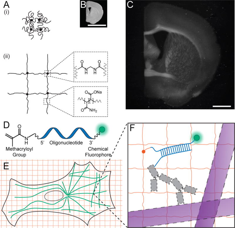
We first set out to see whether a well-known property of polyelectrolyte gels, namely that dialyzing them in water causes expansion of the polymer network into extended conformations (Fig. 1A (1)), could be performed in the context of a biological sample. We infused, into chemically fixed and permeabilized brain tissue (Fig. 1B), sodium acrylate, a monomer used to produce super-absorbent materials ((2),(3)), along with the co-monomer acrylamide and the crosslinker N-N’-methylenebisacrylamide. After triggering free radical polymerization with ammonium persulfate (APS) initiator and tetramethylethylenediamine (TEMED) accelerator, we treated the tissue-polymer composite with protease to homogenize its mechanical characteristics. Following proteolysis, dialysis in water resulted in a 4.5-fold linear expansion, without distortion at the level of gross anatomy (Fig. 1C). We found the digestion to be uniform throughout the slice (Fig. S1). Expanded specimens were transparent (Fig. S2), as they consist largely of water. Thus, polyelectrolyte gel expansion is possible when the polymer is embedded throughout a biological sample.
Figure 1. Expansion microscopy (ExM) concept.

(A) Schematic of collapsed polyelectrolyte network (i), showing crosslinker (dot) and polymer chain (line), and expanded network (ii) after H2O dialysis. (B) Photograph of fixed mouse brain slice. (C) Photograph, post-ExM, of the sample (B) under side illumination. (D) Schematic of label that can be anchored to the gel at site of a biomolecule. (E) Schematic of microtubules (green) and polymer network (orange). (F) The label of (D), hybridized to the oligo-bearing secondary antibody (gray) bound via the primary (gray) to microtubules (purple), is incorporated into the gel (orange lines) via the methacryloyl group (orange dot) and remains after proteolysis (dotted lines). Scale bars: (B), (C) 5 mm. Schematics are not to scale.
We developed a fluorescent labeling strategy compatible with the proteolytic treatment and subsequent tissue expansion described above, to see if fluorescence nanoscopy would be possible. We designed a custom fluorescent label (Fig. 1D) that can be incorporated directly into the polymer network, and thus survive the proteolytic digestion of endogenous biomolecules. This label is tri-functional, comprising a methacryloyl group capable of participating in free radical polymerization, a chemical fluorophore for visualization, and an oligonucleotide that can hybridize to a complementary sequence attached to an affinity tag (e.g., a secondary antibody) (Fig. 1E, 1F). Thus, the fluorescent tag is targeted to a biomolecule of interest, yet remains anchored covalently with high yield (Table S1) to the polymer network. This entire process of labeling, gelation, digestion, and expansion we called expansion microscopy (ExM).
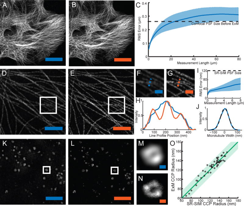
We performed fluorescence imaging using ExM, examining microtubules in fixed HEK293 cells labeled with the tri-functional label and imaged with confocal laser scanning microscopy pre- vs. post-ExM processing. The post-ExM image (Fig. 2B) was registered to the pre-ExM image (Fig. 2A) via a similarity transformation resulting in visually indistinguishable images. To quantify the isotropy of ExM, we calculated the deformation vector field between the images via a non-rigid registration process (Fig. S3). From this vector field, we quantified the root-mean-square error of feature measurements post-ExM, and found that the errors in length were small (<1% of distance, for errors larger than the imaging system point spread function size) (Fig. 2C, n = 4 samples). Throughout the paper, all distances measured in the post-expansion specimen are reported divided by the expansion factor (see Methods).
Figure 2. Expansion microscopy physically magnifies, with nanoscale isotropy.

We compared images acquired via conventional microscopy (blue scale bars) vs. images acquired post-expansion (orange scale bars). (A) Confocal image of microtubules in HEK293 cells. (B) Post-expansion confocal image of sample (A). (C) Root-mean-square (RMS) length measurement error of pre- vs. post-ExM confocal images of cultured cells (blue line, mean; shaded area, standard deviation; n = 4 samples). (D) Super-resolution structured-illumination microscopy (SR-SIM) image of microtubules. (E) Post-expansion confocal image of the sample of (D). (F), (G) Magnified views of boxed regions of (D) and (E) respectively. (H) Profiles of microtubule intensity taken along the blue and orange dotted lines in (F) and (G). (I) RMS length measurement error of ExM vs. SR-SIM images (blue line, mean; shaded area, standard deviation; n = 4 samples). (J) Transverse profile of a representative microtubule (blue line), with Gaussian fit (black dotted line). (K) SR-SIM image of clathrin coated pits (CCPs) in HEK293 cells. (L) Post-expansion confocal image of the sample of (K). (M), (N) Magnified views of a single CCP in the boxed regions of (K) and (L) respectively. (O) Scatterplot of radii of CCPs measured via ExM vs. SR-SIM (n = 50 CCPs from 3 samples). Green line, y = x line; shaded green region, half-pixel width of digitization error about the y = x line. Scale bars for pre- vs. post-ExM images: (A) 20 μm, (B) 20 μm (physical size post-expansion, 81.6 μm); (D) 2 μm, (E) 2 μm (9.1 μm); (F) 500 nm, (G) 500 nm (2.27 μm); (K) 2 μm, (L) 2 μm (8.82 μm); (M) 100 nm, (N) 100 nm (441 nm).
We next compared pre-ExM conventional super-resolution images to post-ExM confocal images. We labeled features traditionally used to characterize the performance of super-resolution microscopes, including microtubules ((4),(5)) and clathrin coated pits (6), and imaged them with a super-resolution structured illumination microscope (SR-SIM) pre-ExM, and a spinning disk confocal post-ExM. Qualitatively (Fig. 2D, 2E), the images were similar, and quantitatively (Fig. 2I), measurement errors were again on the order of 1%, and well within the point spread function size of the SR-SIM microscope (n = 4 samples). Microtubule networks were more sharply resolved in ExM (Fig. 2G) than with SR-SIM (Fig. 2F). ExM resolved individual microtubules that could not be distinguished with SR-SIM (Fig. 2H). Microtubules imaged with ExM presented a full-width at half-maximum (FWHM; Fig. 2J) of 82.4 ± 6.01 nm (mean ± standard deviation, n = 24 microtubules from 3 samples). This FWHM reflects the effective resolution of ExM convolved by the width of the labeled microtubule. To estimate the effective resolution of ExM, we deconvolved (as in (7)) our observed microtubule FWHM by the known immunostained microtubule width (55 nm (6)), conservatively ignoring the width of the tri-functional label, and obtained an effective resolution for ExM of ~60 nm. This conservative estimate is comparable to the diffraction-limited confocal resolution (~250 nm lateral resolution (8)) divided by the expansion factor (~4.5).
Clathrin coated pits were also well resolved (Fig. 2K, 2L). ExM resolved the central nulls of the pits better than SR-SIM (Fig. 2M, 2N). Clathrin-coated pit radii measured via ExM and SR-SIM were highly correlated, with a slope of 1.001 (total least squares regression, confidence interval .013 with P <0.05, n = 50 pits from 3 samples) (Fig. 2O). 49 of the 50 points lay within a half-pixel distance of the unity slope line, suggesting that variation in the ExM vs. SR-SIM comparison was within the digitization error of the measurement.
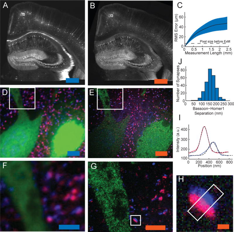
We next applied ExM to fixed brain tissue. Slices of brain from Thy1-YFP-H mice expressing cytosolic YFP under the Thy1 promoter in a subset of neurons (9) were stained with a tri-functional label bearing Alexa 488, using anti-GFP primary antibodies (which also bind YFP). Slices expanded ~4×, similar to the expansion factor in cultured cells. We compared pre- vs. post-ExM images taken on an epifluorescence microscope. As with cultured cells, the post-ExM image (Fig. 3A) was registered to the pre-ExM image (Fig. 3B) via a similarity transformation. The registered images closely matched, although some features moved in or out of the depth of field, due to the axial expansion post-ExM. Quantitatively, post-ExM measurement errors (Fig. 3C, n = 4 cortical slices) were 2–4%.
Figure 3. ExM imaging of mammalian brain tissue.

(A) Widefield image of Thy1-YFP mouse brain slice showing fluorescence (white). (B) Post-expansion widefield image of sample (A). (C) Root-mean-square (RMS) length measurement error for pre- vs. post-ExM images of brain slices (blue line, mean; shaded area, standard deviation; n = 4 samples). (D), (E) Confocal fluorescence images of boxed regions in (A) and (B) respectively, stained with pre-synaptic (anti-Bassoon, blue) and post-synaptic (anti-Homer1, red) markers, in addition to anti-GFP (green), pre- (D) vs. post- (E) expansion. (F), (G) Details of boxed regions in (D) and (E). (H) Single representative synapse highlighted in (G). (I) Staining intensity for Bassoon (blue) and Homer1 (red) of the sample of (H) along white box long axis. Dotted black lines, Gaussian fits. a.u., arbitrary units. (J) Bassoon-Homer1 separation (n = 277 synapses from 4 cortical slices). Scale bars for pre vs. post-ExM images: (A) 500 μm, (B) 500 μm (physical size post-expansion 2.01 mm); (D) 5 μm, (E) 5 μm (20.1 μm); (F) 2.5 μm, (G) 2.5 μm (10.0 μm) and (H) 250 nm (1.00 μm).
We synthesized tri-functional labels with different colors and oligonucleotides (see Methods) to enable multicolor ExM. We obtained pre- (Fig. 3D) vs. post-ExM (Fig. 3E) images of Thy1-YFP-H mouse cortex with ExM labels directed against YFP (green) and the pre- and post-synaptic scaffolding proteins Bassoon (blue) and Homer1 (red). In the pre-ExM image, Bassoon and Homer1 staining form overlapping spots at each synapse (Fig. 3F), while the post-ExM image (Fig. 3G) shows clearly distinguishable pre- and post-synaptic labeling. We quantified the distance between the Bassoon and Homer1 scaffolds, as measured by ExM. We fit the distributions of Bassoon and Homer1 staining intensity, taken along the line perpendicular to the synaptic cleft (Fig. 3H, boxed region), to Gaussians (Fig 3I). The Bassoon-Homer1 separation was 169 ± 32.6 nm (Fig. 3J, n = 277 synapses from 4 cortical slices), similar to a previous study using STORM in the ventral cortex and olfactory bulb, which obtained ~150 nm separation (10). We also imaged other antibody targets of interest in biology (Fig. S4).
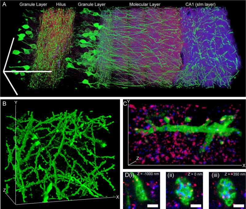
To explore whether expanded samples, scanned on fast diffraction-limited microscopes, could support scalable super-resolution imaging, we imaged a volume of the adult Thy1-YFP-H mouse brain spanning 500 μm × 180 μm × 100 μm (a typical slice thickness for immunohistochemistry), with three labels (Fig. 4A; anti-GFP, green; anti-Homer1, red; anti-Bassoon, blue). The diffraction limit of our confocal spinning disk microscope (with 40×, 1.15 NA, water immersion objective), divided by the expansion factor, yields an estimated effective resolution of ~70 nm laterally and ~200 nm axially. Shown in Fig. 4A is a 3D rendered image of the dataset (see Movie S1 for animated rendering). Zooming into the raw dataset, nanoscale features emerge (Fig. 4B–D). We performed a volume rendering of the YFP-expressing neurons in a subset of CA1 stratum lacunosum moleculare (slm), revealing spine morphology (Fig. 4B and Movie S2). Focusing on a dendrite in CA1 slm, we observed the post-synaptic protein Homer1 to be well localized to dendritic spine heads, with the presynaptic molecule Bassoon in apposition (Fig. 4C and Movie S3). Examination of a mossy fiber bouton in the hilus of the dentate gyrus reveals invaginations into the bouton by spiny excrescences of the opposing dendrite, as observed previously via electron microscopy (11) (Fig. 4D). Thus, ExM enables multiscale imaging and visualization of nanoscale features, across length scales relevant to understanding neural circuits.
Figure 4. Scalable 3D super-resolution microscopy of mouse brain tissue.

(A) Volume rendering of a portion of hippocampus showing neurons (expressing Thy1-YFP, shown in green) and synapses (marked with anti-Bassoon (blue) and anti-Homer1 (red)). (B) Volume rendering of dendrites in CA1 stratum lacunosum moleculare (slm). (C) Volume rendering of dendritic branch in CA1 slm. (D) Mossy fiber bouton in hilus of the dentate gyrus. Panels (i–iii), selected z-slices. Scale bars: (A) 100 μm in each dimension; (B) 52.7 μm (x), 42.5 μm (y), and 35.2 μm (z); (C) 13.5 μm (x), 7.3 μm (y), and 2.8 μm (z); (D) (i–iii) 1 μm.
In summary, we report the discovery of a new modality of magnification, namely that fixed cells and tissues, appropriately labeled and processed, can be physically magnified, with isotropic nanoscale resolution (effective ~60 nm lateral resolution). Although acrylate esters have been used for antigen-preserving embedding for electron microscopy ((12),(13)), ExM represents the first use of an embedded polyelectrolyte gel, used here to expand the specimen. Super-resolution imaging methods are slower than their diffraction-limited counterparts because they must resolve more voxels per unit volume. ExM achieves this effect by expanding the voxels physically. ExM achieves the same voxel throughputs as a diffraction-limited microscope, but at the voxel sizes of a super-resolution microscope. Ongoing technology trends for faster diffraction-limited microscopy (14) will continue to boost ExM speed.
The physical magnification of ExM enables super-resolution imaging with several fundamental new properties. The axial effective resolution is improved by the same factor as the lateral effective resolution. ExM can achieve super-resolution with standard fluorophores, and on a diffraction-limited microscope. Super-resolution imaging is often performed within ~10 μm of the sample surface due to low signal-to-noise, scattering and refractive index mismatch. We were able to perform 3-color super-resolution imaging of a large volume of brain tissue over an axial extent of 100 μm with a spinning disk confocal microscope. Because the ExM-processed sample is almost entirely water, eliminating scattering, ExM may empower fast methods like light-sheet microscopy (15) to become super-resolution methods. ExM potentially enables labels to be situated within a well-defined, in vitro-like environment, facilitating in situ analysis (16). Since the sample is physically larger, any mechanical errors in post-expansion sectioning, or stage drift, are divided by the expansion factor.
The performance of ExM suggests that despite statistical fluctuations in polymer chain length at the molecular scale, at the nanoscale distances here examined, these fluctuations average out, yielding isotropy. Estimates of mesh size for comparable gels suggest that the distance between nearest-neighbor polymer chains are in the ~1–2 nm range ((17),(18)). By tuning the material properties of the ExM polymer, e.g. the density of cross-links, yet higher effective resolutions may be possible.
Supplementary Material
Acknowledgments
ESB was funded by NIH Director’s Pioneer Award 1DP1NS087724 and NIH Transformative Research Award 1R01MH103910-01, the New York Stem Cell Foundation-Robertson Investigator Award, the MIT Center for Brains Minds and Machines NSF CCF-1231216, Jeremy and Joyce Wertheimer, Google, NSF CAREER Award CBET 1053233, the MIT Synthetic Intelligence Project, the MIT Media Lab, the MIT McGovern Institute, and the MIT Neurotechnology Fund. FC was funded by an NSF Graduate Fellowship. PWT was funded by a Fannie and John Hertz Graduate Fellowship.
Confocal imaging was performed in the W.M. Keck Facility for Biological Imaging at Whitehead Institute for Biomedical Research. Deltavision OMX SR-SIM imaging was performed at the Koch Institute Swanson Biotechnology Center imaging core. We would like to acknowledge Wendy Salmon and Eliza Vasile for assistance with confocal and SR-SIM imaging. We would like to acknowledge Nikita Pak for assistance with perfusions. We would also like to acknowledge, for helpful discussions, Brian Chow, Adam Marblestone, George Church, Peter So, Scott Manalis, Jae-Byum Chang, Juan Enriquez, Ishan Gupta, Mehran Kardar, and Alex Wissner-Gross.
Footnotes
There is no conflict of interest for any of the authors. The authors have applied for a patent on the technology, assigned to MIT. FC and PWT conducted experiments. FC, PWT, and ESB generated ideas, analyzed and interpreted data, and wrote the paper. The order of co-first author names was determined by a coin toss. The imaging and other data reported in the paper are available upon request.
Supplementary Materials:
Materials and Methods
References 19–28
References and Notes
- 1.Tanaka T, et al. Phase Transitions in Ionic Gels. Phys Rev Lett. 1980;45:1636–1639. [Google Scholar]
- 2.Ohmine I. Salt effects on the phase transition of ionic gels. J Chem Phys. 1982;77:5725. [Google Scholar]
- 3.Buchholz FL. in Superabsorbent Polymers. 1994;573:27–38. [Google Scholar]
- 4.Huang B, Jones SA, Brandenburg B, Zhuang X. Whole-cell 3D STORM reveals interactions between cellular structures with nanometer-scale resolution. Nat Methods. 2008;5:1047–1052. doi: 10.1038/nmeth.1274. [DOI] [PMC free article] [PubMed] [Google Scholar]
- 5.Rego EH, et al. PNAS Plus: Nonlinear structured-illumination microscopy with a photoswitchable protein reveals cellular structures at 50-nm resolution. Proc Natl Acad Sci. 2012;109:E135–E143. doi: 10.1073/pnas.1107547108. [DOI] [PMC free article] [PubMed] [Google Scholar]
- 6.Bates M, Huang B, Dempsey GT, Zhuang X. Multicolor super-resolution imaging with photo-switchable fluorescent probes. Science. 2007;317:1749–1753. doi: 10.1126/science.1146598. [DOI] [PMC free article] [PubMed] [Google Scholar]
- 7.Olivier N, Keller D, Gönczy P, Manley S. Resolution Doubling in 3D-STORM Imaging through Improved Buffers. PLoS One. 2013;8 doi: 10.1371/journal.pone.0069004. [DOI] [PMC free article] [PubMed] [Google Scholar]
- 8.Cole RW, Jinadasa T, Brown CM. Measuring and interpreting point spread functions to determine confocal microscope resolution and ensure quality control. Nat Protoc. 2011;6:1929–41. doi: 10.1038/nprot.2011.407. [DOI] [PubMed] [Google Scholar]
- 9.Feng G, et al. Imaging neuronal subsets in transgenic mice expressing multiple spectral variants of GFP. Neuron. 2000;28:41–51. doi: 10.1016/s0896-6273(00)00084-2. [DOI] [PubMed] [Google Scholar]
- 10.Dani A, Huang B, Bergan J, Dulac C, Zhuang X. Superresolution Imaging of Chemical Synapses in the Brain. Neuron. 2010;68:843–856. doi: 10.1016/j.neuron.2010.11.021. [DOI] [PMC free article] [PubMed] [Google Scholar]
- 11.Rollenhagen A, Lübke JHR. The mossy fiber bouton: the “common” or the “unique” synapse? Front Synaptic Neurosci. 2010;2:2. doi: 10.3389/fnsyn.2010.00002. [DOI] [PMC free article] [PubMed] [Google Scholar]
- 12.Newman GR, Jasani B, Williams ED. A simple post-embedding system for the rapid demonstration of tissue antigens under the electron microscope. Histochem J. 1983;15:543–555. doi: 10.1007/BF01954145. [DOI] [PubMed] [Google Scholar]
- 13.Micheva KD, Smith SJ. Array Tomography: A New Tool for Imaging the Molecular Architecture and Ultrastructure of Neural Circuits. Neuron. 2007;55:25–36. doi: 10.1016/j.neuron.2007.06.014. [DOI] [PMC free article] [PubMed] [Google Scholar]
- 14.Chen BC, et al. Lattice light-sheet microscopy: Imaging molecules to embryos at high spatiotemporal resolution. Science (80-) 2014;346:1257998. doi: 10.1126/science.1257998. [DOI] [PMC free article] [PubMed] [Google Scholar]
- 15.Huisken J, Swoger J, Del Bene F, Wittbrodt J, Stelzer EHK. Optical sectioning deep inside live embryos by selective plane illumination microscopy. Science. 2004;305:1007–1009. doi: 10.1126/science.1100035. [DOI] [PubMed] [Google Scholar]
- 16.Lee JH, et al. Highly multiplexed subcellular RNA sequencing in situ. Science. 2014;343:1360–3. doi: 10.1126/science.1250212. [DOI] [PMC free article] [PubMed] [Google Scholar]
- 17.Hecht AM, Duplessix R, Geissler E. Structural inhomogeneities in the range 2.5–2500. ANG. in polyacrylamide gels. Macromolecules. 1985;18:2167–2173. [Google Scholar]
- 18.Calvet D, Wong JY, Giasson S. Rheological monitoring of polyacrylamide gelation: Importance of cross-link density and temperature. Macromolecules. 2004;37:7762–7771. [Google Scholar]
- 19.Preibisch S, Saalfeld S, Tomancak P. Globally optimal stitching of tiled 3D microscopic image acquisitions. Bioinformatics. 2009;25:1463–1465. doi: 10.1093/bioinformatics/btp184. [DOI] [PMC free article] [PubMed] [Google Scholar]
- 20.Otsu N. A Threshold Selection Method from Gray-Level Histograms. IEEE Trans Syst Man Cybern. 1979;9:62–66. [Google Scholar]
- 21.Kroon DJ. B-spline Grid, Image and Point based Registration. Matlab Cent [Google Scholar]
- 22.Ribak CE. Aspinous and sparsely-spinous stellate neurons in the visual cortex of rats contain glutamic acid decarboxylase. J Neurocytol. 1978;7:461–478. doi: 10.1007/BF01173991. [DOI] [PubMed] [Google Scholar]
- 23.Houser CR, Crawford GD, Salvaterra PM, Vaughn JE. Immunocytochemical localization of choline acetyltransferase in rat cerebral cortex: a study of cholinergic neurons and synapses. J Comp Neurol. 1985;234:17–34. doi: 10.1002/cne.902340103. [DOI] [PubMed] [Google Scholar]
- 24.Tighilet B, Hashikawa T, Jones EG. Cell- and lamina-specific expression and activity-dependent regulation of type II calcium/calmodulin-dependent protein kinase isoforms in monkey visual cortex. J Neurosci. 1998;18:2129–2146. doi: 10.1523/JNEUROSCI.18-06-02129.1998. [DOI] [PMC free article] [PubMed] [Google Scholar]
- 25.Hendry SHC, et al. Two classes of cortical GABA neurons defined by differential calcium binding protein immunoreactivities. Exp Brain Res. 1989;76:467–472. doi: 10.1007/BF00247904. [DOI] [PubMed] [Google Scholar]
- 26.Hozák P, Sasseville AM, Raymond Y, Cook PR. Lamin proteins form an internal nucleoskeleton as well as a peripheral lamina in human cells. J Cell Sci. 1995;108(Pt 2):635–644. doi: 10.1242/jcs.108.2.635. [DOI] [PubMed] [Google Scholar]
- 27.Fritschy JM, Weinmann O, Wenzel A, Benke D. Synapse-specific localization of NMDA and GARA(A) receptor subunits revealed by antigen-retrieval immunohistochemistry. J Comp Neurol. 1998;390:194–210. [PubMed] [Google Scholar]
- 28.Choi HMT, et al. Programmable in situ amplification for multiplexed imaging of mRNA expression. Nat Biotechnol. 2010;28:1208–1212. doi: 10.1038/nbt.1692. [DOI] [PMC free article] [PubMed] [Google Scholar]
Associated Data
This section collects any data citations, data availability statements, or supplementary materials included in this article.


