Abstract
Measurements of refractive indices (RIs) of intracellular components can provide useful information on the structure and function of cells. The present study reports, for the first time, determination of the RI of an isolated mitochondrion in isotonic solution using retardation-modulated differential interference contrast microscopy. The value was 1.41 ± 0.01, indicating that mitochondria are densely packed with molecules having high RIs. Further, the RIs of each mitochondrion were significantly correlated with the mitochondrial membrane potential, an index of mitochondrial activity. These results will provide useful information on the structures and functions of cells based on the intracellular distribution of RIs.
OCIS codes: (170.2655) Functional monitoring and imaging, (000.1430) Biology and medicine
1. Introduction
The refractive index (RI) of a cell reflects the structure and composition of the cell. Since the RI can be measured without staining the cell, measurement of the RI provides structural information on cells that have not been damaged by dyes. For these reasons, the RIs of cells have been measured for a variety of cell types [1–6]. In addition, the RI has been considered to provide significant information on activities of cells. For example, the RI values of dysplastic epithelium [3] and cultured cancer cells [4] have been shown to be larger than those of non-cancer cells. Moreover, the RI of human red blood cells has been shown to decrease upon their parasitization by Plasmodium falciparum [5], and the RI of human basophils increases in the presence of anti-IgE antibody [6].
In addition to measurements of the RIs averaged over a whole cell, the intracellular distribution of RIs has been measured quantitatively by using optical microscopy [7–11]. These measurements have shown that the intracellular RIs are heterogeneous [8–11]. Although the regions with large RIs are thought to correspond to organelles, it has been difficult to precisely assign regions with higher RIs to specific organelles based on their RIs since the RIs of the individual organelles are unknown. Therefore, in order to obtain further information regarding intracellular structures based on their measured RIs, it will be necessary to accumulate information on the RIs of intracellular components.
The RI of an organelle depends on the chemical compositions of the organelle. Since each mitochondrion independently undergoes changes including shrinkage and elongation [12–16], changes in individual mitochondrial RI may also occur, resulting in heterogeneity of mitochondrial RIs. Mitochondrial membrane potential (MMP) in a cell has also been reported to be heterogeneous [17]. Since MMP should be affected by both the mitochondria’s individual characteristics and the circumstances specific to each mitochondria, the heterogeneity of the RI, which is one of the mitochondria’s individual characteristics, may contribute to the heterogeneity of MMP. However, the relationship between MMP and RI remains unknown. In the present study, the RIs of individual mitochondria isolated from porcine hearts were determined using retardation-modulated differential interference contrast (RM-DIC) microscopy [18], and correlations between RI and MMP of isolated mitochondria were examined.
2. Methods
2.1 Differential interference contrast (DIC) imaging
To examine the RI of single mitochondria, we measured isolated mitochondria, polystyrene and silica beads using a DIC microscope equipped with a rotary polarizer and a quarter-wave plate according to Ishiwata et al [18]. The optical setup is shown in Fig. 1 .
Fig. 1.
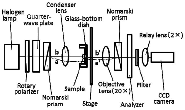
Block diagram of the RM-DIC microscope. By changing the direction of the rotary polarizer, the phase difference between two beams split by Nomarski prism (beam a and beam b) can be modulated. The distance between beam a’ and beam b’ is the shear amount.
DIC images and transmitted light images of individual mitochondria and beads were acquired with an inverted microscope (IX70, Olympus, Tokyo, Japan) equipped with a 20 × objective (UPlanSApo, Olympus), a 2 × relay lens (U-TVCAC, Olympus) and a cooled CCD camera (6.45 μm/pixel at 1x) (Sensicam QE, PCO AG; Kelheim, Germany). The wavelength used for the measurements was selected with a 10-nm bandpass filter centered at 546 nm [19], because the effects of redox changes of mitochondrial proteins on the absorption of mitochondrial suspensions are small within this range of the wavelength. To modulate the phase difference between beam a and beam b in Fig. 1, the direction of the rotary polarizer was changed in 10° steps and images were obtained at 18 different angles of the rotary polarizer. The binning pixel was 1 × 1 and the exposure time was 1 s. The pixel size measured in the objective space was 161 nm/pixel. The shear amount of this system was measured to be 1310 nm. The image data with resolution of 12 bits per pixel were analyzed with image-processing software (MetaMorph: Universal Imaging, Downingtown, PA).
Polystyrene and silica beads were measured in various solutions with different RIs. Isolated mitochondria were measured in isotonic buffer at room temperature. The RIs of the solutions used were measured with a refractometer (ATAGO, Japan) at 546 nm at room temperature.
2.2 Analysis of DIC images
To obtain the phase difference between beam a’ and beam b’ in Fig. 1, the intensity changes at each pixel of the DIC images upon rotating the polarizer were analyzed using Eq. (1):
| (1) |
Here, Ij(x) is the light intensity at a pixel (j, pixel number) when the direction of the rotary polarizer is x, Aj and Bj are constants, Φ0 is the phase at x = 0 when both beam a’ and beam b’ pass through the background, and ΔΦj is the alteration of the phase difference between two beams when either or both beams pass through a phase object. These parameters were obtained by fitting Eq. (1) to the data with the computer program for the least-squares method provided by Microsoft Excel.
The phase shift of the beam (ΔΨ) upon passing through the specimen was calculated by integrating the specimen-induced alterations of the phase difference between two beams with the distance of the shear amount along the shear direction based on the ΔΦj measured at each pixel. Using this ΔΨ, the alteration of optical path length (ΔOPL) induced by the specimen was obtained from Eq. (2):
| (2) |
2.3 Fluorescence imaging
To examine correlations between activity and RI of mitochondria, fluorescence images of tetramethylrhodamine ethyl ester (TMRE) and DIC images were obtained for individual mitochondria. TMRE is a fluorescent dye sensitive to MMP that is an index of mitochondrial activity [20]. For measurements of TMRE fluorescence, excitation light from a 75W xenon lamp was selected with a 15nm band-pass filter centered at 535nm. The intensity of illumination was reduced to 25% with a neutral density filter to avoid photodynamic injury to mitochondria. The fluorescence at >580nm was recorded as images with a resolution of 12 bits per pixel by using the above mentioned cooled CCD camera. The binning pixel was 1 × 1 and the exposure time was 1sec. Prior to the measurements of TMRE fluorescence, 0.2mM malate and 0.5mM glutamate were added. A series of TMRE fluorescence image frames was obtained with intervals of 2sec for 150sec after addition of malate and glutamate [21,22].
2.4 Analysis of TMRE fluorescence
For the examination of mitochondrial activity, TMRE fluorescence intensity at each pixel was normalized by TMRE fluorescence in the buffer, which was measured in the same field as the mitochondria but was obtained at a position where the fluorescence intensity was not affected by mitochondrial TMRE. Here, we defined mitochondrial relative fluorescence intensity (RFI) as this ratio (%). Since RFI at the position of the mitochondrion increases upon addition of respiration substrates and then fluctuates [21,22], the maximum RFIs during the observation for 150 sec were noted for individual mitochondrion (Max.RFI). To eliminate inactive mitochondria from the analysis, we analyzed mitochondria with a Max. RFI larger than 106 because RFIs of mitochondria were smaller than 106% of the background when mitochondria were inactivated in the presence of 15 µM carbonyl cyanide m-chlorophenylhydrazone, a protonophore.
2.5 Electron microscopy and preparation of the specimen
Mitochondria were fixed with 2% glutaraldehyde in suspension buffer for 2 h and washed 3 times for 10 min each with the same buffer. The samples were post-fixed with 1% OsO4 in the buffer for 1 h and washed twice with the same buffer. The samples were then gradually dehydrated with increasing concentrations (50–100%) of ethanol. These steps were carried out at 4 °C. The following steps were carried out at room temperature when not specifically noted. The samples were washed 3 times for 10 min each with propylene oxide. Dehydrated samples were embedded in EPON 812 through successive incubations in increasing EPON 812/propylene oxide ratios (1:1 and 3:1, respectively) and finally in “pure” EPON 812. The embedded mitochondria in EPON 812 were kept at 45 °C for 1 day, and then at 60 °C for 1 day. Ultrathin sections (70 nm) of the EPON block were cut using an ultramicrotome (EM UC7, Leica Microsystems). Sections were mounted on copper grids and stained with 38% meglumine gadoterate solution (Magnescope, TERUMO) and 0.4% lead citrate solution. Micrographs were taken using a transmission electron microscope (JEM-1400, JEOL) at 80 kV.
2.6 Materials
Polystyrene beads (0.99 ± 0.01 μm in diameter, RI = 1.59) and silica beads (0.96 ± 0.05 μm in diameter, RI = 1.43-1.46) were purchased from Polysciences, Inc. (Germany). All chemicals used were of the highest purity commercially available. Prior to microscopic measurements, the beads were adsorbed onto a glass-bottom culture dish and then bathed in an appropriate solution. Sucrose solutions, cedar oil (RI = 1.517) or tung oil (RI = 1.510) were used as solutions with known RIs.
2.7 Preparation of isolated mitochondria
Mitochondria were promptly isolated by differential centrifugation, as previously described [23], from porcine hearts obtained from a local slaughterhouse. The obtained mitochondria were suspended in suspension buffer [10 mM Tris-HCl, 250 mM sucrose, 0.5 mM EGTA, (pH 7.4)]. Each preparation was assayed for ATP production [24] upon addition of 5 mM Na-malate, giving a rate of 329 ± 34 nmol ATP/mg of protein/min (mean ± SE, n = 3), which was comparable to values reported previously [19] and which showed that mitochondria used for the experiments had a high potential for ATP production. Protein content was determined using a BCA protein assay with BSA as a standard.
For microscopic measurements, isolated mitochondria were adsorbed onto glass-bottom culture dishes (35 mm in diameter) by placing 200 μl of mitochondria suspension (0.02mg of protein/ml) on a dish for 2h and were then washed twice with the buffer [25,26]. Adsorption and washing were performed at 4°C. Before observation, isolated mitochondria on a dish were incubated for 2 min at 25 °C in isotonic buffer [10mM Tris-HCl, 250mM sucrose, 0.5mM EGTA, 2mM KH2PO4, 0.5mM MgCl2, 0.5mM ADP, 1 μM oligomycin, 10nM TMRE, pH 7.4].
2.8 Statistical analysis
Data produced using mitochondria prepared from three porcine hearts were analyzed. Correlations between variables were examined using Spearman's rank correlation coefficient, and values of P < 0.05 were considered statistically significant.
3. Results
3.1 Measurements of a fused silica glass plate with the RM-DIC microscope
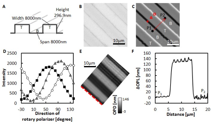
To evaluate the accuracy of measurements with the RM-DIC microscope, a fused silica glass plate having periodic grooves with a known refractive index (1.46 at 546 nm) and a known depth (296.9 nm) shown in Figs. 2(A) and 2(B) was measured. Figure 2(C) shows periodic bright and dark lines corresponding to the periodic grooves. The light intensities on these lines and in the regions between them changed depending on the direction of the rotary polarizer as shown in Fig. 2(D). Using equations Eqs. (1)-(2), 133.5nm was obtained as the average ΔOPL caused by the difference in level on a fused silica glass plate as shown in Figs. 2(E) and 2(F). This ΔOPL corresponds to 1.45 as a refractive index of fused silica glass. The obtained value of 1.45 is in good agreement with the reported value of the refractive index of fused silica glass.
Fig. 2.
(A) A fused silica glass plate with grooves. T and B indicate the top and bottom region of the plate, respectively. (B) Transmitted light image of the plate. (C) DIC image of the plate when the rotary polarizer angle was 40°. T and B correspond to the T and B shown in (A). (D) Intensity changes upon rotation of the polarizer. The indicators show the light intensities at the corresponding positions in (C). (E) ΔOPL map of the plate. The ΔOPLs on the red dotted line were set to 0 nm. (F) Changes in ΔOPLs along the shear direction. ΔOPL at P1 is set to 0 nm. P1 and P2 are the points shown in (C).
3.2 Measurements of single beads with the RM-DIC microscope
Isolated mitochondria in isotonic buffer are spherical with a diameter of approximately 0.5–2.0 μm. Unlike a parallel plate object, determination of the RI of a spherical object is not simple. To examine the mitochondrial RI, we determined the calibration curve which shows the relationship between ΔOPL and RI difference (the RI of spherical object – the RI of the surrounding solution) by using beads with a diameter of 1 μm.
Figure 3(A) shows the DIC image of a silica bead in water. Since the shear amount (1310nm) was larger than the diameter of the bead, the dark and bright images were separated. The intensities of the light on the image varied sinusoidally with the direction of the rotary polarizer, and the phases depended on the position in the image as shown in Fig. 3(B). A ΔOPL map of the bead in Fig. 3(C) was obtained by using Eqs. (1)-(2). The maximum of ΔOPLs (Max. ΔOPL) was observed at the center of the bead as shown in Fig. 3(D), at 53.1 ± 3.2 nm (mean ± SD, N = 9). Next, the size of the bead was estimated by analyzing the transmitted light image as demonstrated in Fig. 3(E). Figure 3F shows the intensity profile of the transmitted light along a line through the center of the bead. By fitting a Gaussian curve to the intensity changes observed, 740 ± 15 nm (mean ± SD, N = 10) was obtained as the calculated half width. In the following section, for simplicity, we use the expression “half widths of mitochondria or beads” instead of “the half widths of Gaussian curves fitted to the intensity changes along lines through the centers of the transmitted light images of mitochondria or beads”.
Fig. 3.
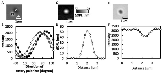
Measurements of a silica bead with a diameter of 1μm. (A) DIC image of a silica bead in water when the direction of the rotary polarizer was 150°. (B) The changes in light intensity upon rotating the rotary polarizer. Circles, triangles and squares indicate the intensity at the corresponding regions shown in (A). The solid lines are the curves obtained by fitting Eq. (1) to the data. (C) ΔOPL map of a bead. (D) Changes in ΔOPL along a line through the center of the bead image (open circle). The solid line shows the interpolation curve. (E) Transmitted light image of a bead. (F) Changes in the intensity of the transmitted light along a line through the center of the bead image (open circle). The solid line shows the approximated curve obtained by fitting the Gaussian function to the data.
Next, we determined the refractive index of the silica beads because the supplier did not provide the exact RI of the silica beads. When we observed the transmittance images of the beads in sucrose solutions with the RIs of 1.42, 1.43, 1.44, 1.45, and 1.46, the contrast of the images was faintest in the sucrose solution with the RI of 1.43. Based on this result, we concluded that the refractive index of the silica beads was between 1.42 and 1.44.
To examine the effects of differences in RI values between solutions and beads on the Max.ΔOPL, Max.ΔOPLs induced by single silica beads were measured in various solutions with different RIs, the results of which are shown in Fig. 4 . Although the theoretical curves to be fitted to the data are not clear, we obtained a well approximated curve by fitting a polynomial of the second degree to the data produced Eq. (3):
| (3) |
Here, Δn is the RI of a spherical object having a diameter of 1μm (RIo) minus the RI of the surrounding medium (RIm), when RIo > RIm, C and D are constants. The relationship between the Δn and Max.ΔOPL was not linear, because the path length of the beam in a bead becomes longer by refraction when the RI of the bead is larger than the RI of the surrounding solution.
Fig. 4.
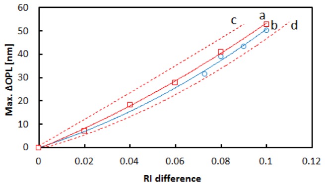
The relationship between RI difference (Δn) and Max.ΔOPL observed for the silica and polystyrene bead. Δn is the difference in RI between the beads and the surrounding medium (See the text for exact definition). Red squares and blue circles show the measured Max.ΔOPLs for silica beads when the RI was assumed to be 1.43 and for polystyrene beads with the RI of 1.59, respectively. Curves a and b (red and blue solid curves) show the approximated curves obtained by fitting Eq. (3) to the data using the least-squares method. Curves c and d (red broken curves) show the approximated curves for silica beads when the RI was assumed to be 1.42 and 1.44, respectively.
In Fig. 4, the approximated curve obtained for polystyrene beads (curve b) was similar to the curve for silica beads when the RI was assumed to be 1.43 and located between the curve for silica beads with the assumed RI of 1.42 and the curve for silica beads with the assumed RI of 1.44. Therefore, we concluded that the relationship between Δn and Max.ΔOPL did not significantly depend on the refractive index of the spherical objects to the extent that the error of the refractive index is ± 0.01 under the present conditions.
3.3 RI of isolated mitochondria
To determine the RI of isolated mitochondria in isotonic solution, the Max.ΔOPLs induced by individual mitochondria adsorbed on a cover slip were measured as shown in Fig. 5 . Since the Max.ΔOPL induced by a mitochondrion should be a function of its diameter, we limited the analysis to mitochondria with half widths of approximately 740 nm, which is the half width of a bead having a diameter of 1 μm. In addition, to avoid damaged mitochondria, we selected active mitochondria based on the TMRE fluorescence. The RI value for each mitochondrion was calculated based on the Max.ΔOPL using curve a in Fig. 4 and the RI value of the isotonic buffer (1.35). The mitochondrial RI was 1.41 ± 0.01 (mean ± SD, N = 22). As shown in Table 1 , the RI did not change significantly when we expanded the range of the half widths to 680-800 nm, indicating that the RI did not change within this range. Also, the mitochondrial RI did not significantly depend on the calibration curves (curves a-d) shown in Fig. 4, having the average RI of 1.41.
Fig. 5.
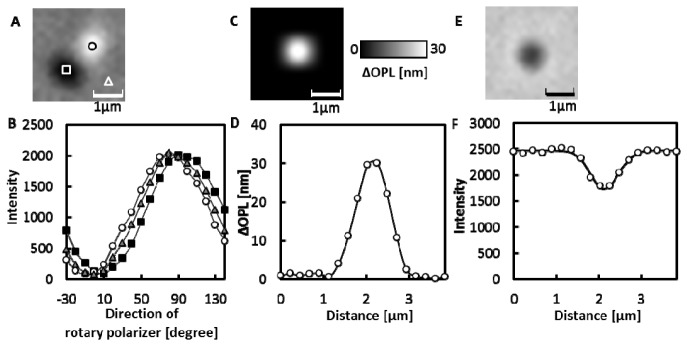
Measurements of a single isolated mitochondrion. (A) DIC image of a mitochondrion in the isotonic buffer when the direction of the rotary polarizer was 40°. (B) The changes in the light intensity upon rotating the rotary polarizer. Circles, triangles, and squares indicate the intensity at the corresponding regions shown in (A). The solid lines are curves obtained by fitting Eq. (1) to the data. (C) ΔOPL map of a mitochondrion. (D) Changes in the ΔOPL along a line through the center of the mitochondrion image (open circle). The solid line is the interpolation curve. (E) A transmitted light image of a mitochondrion. (F) The changes in the intensity of the transmitted light along a line through the center of the mitochondrion image (open circle). The solid line is the approximated curve obtained by fitting the Gaussian function to the data.
Table 1. RIs of mitochondria with different ranges of the half widths.
| Range of half width [nm]a | Nb | Half width [nm]c | Max.ΔOPL[nm]d | RIe |
|---|---|---|---|---|
| 710–770 | 10 | 735 ± 2 | 32 ± 7 | 1.41 ± 0.01 |
| 700–780 | 15 | 734 ± 3 | 31 ± 7 | 1.41 ± 0.01 |
| 690–790 | 20 | 736 ± 3 | 30 ± 7 | 1.41 ± 0.01 |
| 680–800 | 22 | 741 ± 3 | 30 ± 7 | 1.41 ± 0.01 |
a: Half widths were obtained as described in section 3.2.
b: The number of analyzed mitochondria.
c,d,e: The data were expressed as the mean ± SD.
e: The RIs were calculated with Eq. (3) by assuming the RI of silica beads was 1.43.
Under the present condition, the black image and the white image were completely separated along the shear direction. The polarizing directions of the beams through mitochondria that make black images and white images are mutually orthogonal. Therefore, if the effect of birefringence of mitochondria on the observed ΔOPL is significant, the ΔOPL obtained for the black image should be different from the ΔOPL obtained for the white image. For most mitochondria, ΔOPLs obtained with the black image were the same as the ΔOPLs obtained with the white image within experimental error. This indicates that the effect of birefringence of mitochondria on the observed ΔOPL is negligible.
3.4 Heterogeneity of intramitochondrial structures of isolated mitochondria
To confirm the heterogeneity of sizes and internal structures of isolated mitochondria, isolated mitochondria were visualized using electron microscopy. As shown in Fig. 6 , the mitochondrial sizes and the densities of cristae were heterogeneous. It should be noted that the internal densities of cristae were heterogeneous even among mitochondria having similar sizes.
Fig. 6.
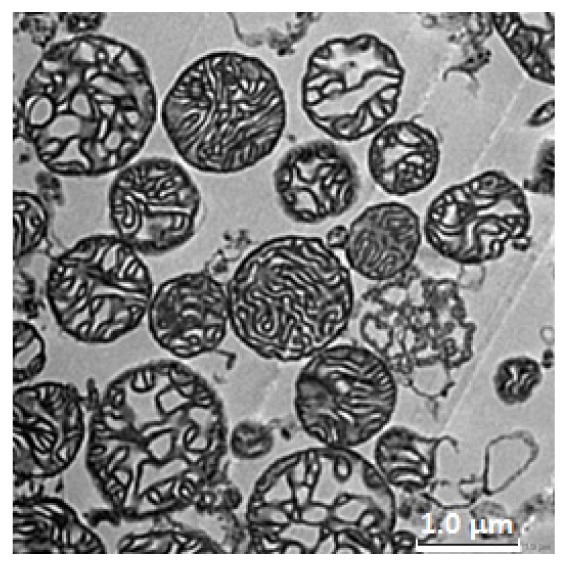
Electron microscopic images of isolated mitochondria. Mitochondria were stained with meglumine gadoterate and lead citrate. The images were taken using a transmission electron microscope as described in section 2.5.
3.5 The correlation between RI and activity of isolated mitochondria
To examine correlations between RI and activity of individual mitochondria, RFIs of single isolated mitochondria were measured after the measurements of ΔOPLs as shown in Fig. 7(A) . The effect of labelling with TMRE on the ΔOPL of mitochondria was negligible, because the ΔOPL of mitochondria did not change before and after labelling with TMRE (data not shown). Figure 7(B) shows that the Max.RFI was observed at the center of the mitochondrion. The Max.RFIs were heterogeneous among individual mitochondria. To eliminate the possible effects of size differences among individual mitochondria on the Max.ΔOPL and the Max.RFI, only mitochondria with half widths in the range 680-800nm were analyzed. For these mitochondria, there were no significant correlations between half width and Max.RFI with a Spearman's rank correlation coefficient (rs) of 0.272 (N = 22), or between half width and Max.ΔOPL with rs of 0.202 (N = 22) as demonstrated in Figs. 7(C) and 7(D). On the other hand, there was a clear correlation between Max.ΔOPL and Max.RFI with rs of 0.642 (P<0.05, N = 22) as shown in Fig. 7(E), indicating that there were significant correlations between the RI and activity of mitochondria.
Fig. 7.
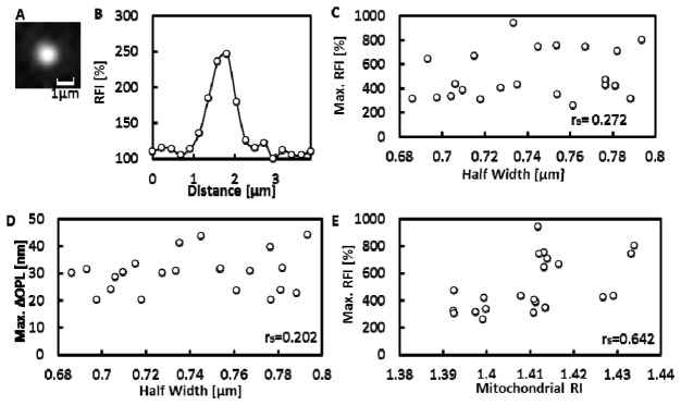
The correlation between Max.ΔOPL and TMRE fluorescence of mitochondria. (A) TMRE fluorescence image of a mitochondrion. (B) Changes in RFIs along a line through the center of the mitochondrion image. (C-E) Isolated mitochondria with half width of 680-800 nm were analyzed (N = 22), rs is the Spearman's rank correlation coefficient. (C) The correlation diagram between Max.RFI and half width of isolated mitochondria. (D) The correlation diagram between Max.ΔOPL and half width. (E) The correlation diagram between RI and Max.RFI of isolated mitochondria The RI was calculated with Eq. (3) by assuming the RI of silica beads was 1.43.
4. Discussions
The average RI value of isolated mitochondria in isotonic buffer was determined to be 1.41 ± 0.01 using RM-DIC microscopy. The RI of each mitochondrion was significantly correlated with the activity.
We reconstructed ΔOPL from the phase differences measured with the RM-DIC by integrating the phase differences along the shearing direction. Therefore, the integrating noise will appear during reconstructing the ΔOPL of the object larger than the shear amount. This could be the reason why the RI we obtained for the fused silica glass plate (1.45) was different from the known value (1.46). On the other hand, for the objects smaller than the shear amount such as mitochondria or beads, the dark and bright images of the objects are completely separated. The phase differences obtained from the analysis of pixels on these separated images are the phase differences between the beam through the object and the beam through the background. Therefore, we calculated the ΔOPL without integrating noises obtained from each pixel. This leads to three advantages: 1) the noise on a pixel did not affect the ΔOPL obtained from the other pixels, 2) by averaging light intensities on the pixels in the background, the effect of the noise on pixels in the background will be decreased, 3) we can omit the beads or mitochondria from analysis when Max. ΔOPLs obtained from the two separated images are significantly different due to the noises.
The RI value of isolated mitochondria was higher than RI values for whole cells (1.35-1.37) [8–10, 27]. This indicates that mitochondria are densely packed with molecules having high RIs, further suggesting that the concentration of proteins and lipids in mitochondria is higher than that in the cytosol. Choi and associates reported that small particles with a high RI value (1.417) were observed in cells [8]. The reported value is in good agreement with our result, and the particles might be mitochondria. However, the percentage of the area with the RI > 1.40 in cells was small [8] compared to the mitochondrial area in mammalian cells. This may be because the RIs measured in cells are the RIs averaged over the cytosol, organelles with low RI values, and mitochondria. Alternatively, the higher RI of isolated mitochondria may be due to the shrinkage of mitochondria, since intracellular mitochondria are known to be elongated to form a rod-like shape or mitochondrial network, unlike isolated mitochondria. Alternatively, the RI value of porcine heart mitochondria may be higher than those of mitochondria in cells analyzed in previous studies.
Electron microscopy showed the heterogeneity of cristae densities in mitochondria. The RI of a mitochondrion with a higher cristae density should be larger than the RI of a mitochondrion with a lower cristae density and higher water content, since the RI of water is smaller than the RIs of proteins or lipids. Thus, heterogeneity of mitochondrial cristae densities may induce heterogeneity of mitochondrial RIs. This explains the correlation between RI and activity observed in the present study. Mitochondria with higher cristae density will be more active due to their larger number of proton pumps, since the proton pumps exist in the inner mitochondrial membranes, including the cristae. In the present study, we analyzed highly active individual mitochondria to avoid mingling of data from intact and damaged mitochondria. Significant correlations were found between activity and RI of active mitochondria, and these results offer evidence that swelling/shrinkage of mitochondria or formation/disruption of the cristae might act as a regulation mechanism of mitochondrial activity.
The present study determined the mitochondrial RI for the first time and investigated the correlation between RI and activity of mitochondria. Although several problems in the measurements of intracellular distributions of RIs remain to be overcome, the present results provide useful information for elucidating cellular structures and activities based on the measurement of RIs. Further, the present method will be available for many biological researchers, because the optical setup of RM-DIC is completed by a slight modification of conventional DIC setup.
Acknowledgments
We thank Mr. R. Saito and Mr. M. Kanao (Olympus Corporation) for kind permission to use the fused silica glass plate. This work was supported in part by a Grant-in-Aid for Scientific Research (B) No. 25286029 and by a Grant-in-Aid for Scientific Research (C) No. 25440065 from the Japan Society for the Promotion of Science (JSPS). We would like to dedicate this article to celebrate the 20th anniversary of the Department of Biotechnology and Life Science at Tokyo University of Agriculture and Technology.
References and links
- 1.Barer R., “Refractometry and interferometry of living cells,” J. Opt. Soc. Am. 47(6), 545–556 (1957). 10.1364/JOSA.47.000545 [DOI] [PubMed] [Google Scholar]
- 2.Lue N., Popescu G., Ikeda T., Dasari R. R., Badizadegan K., Feld M. S., “Live cell refractometry using microfluidic devices,” Opt. Lett. 31(18), 2759–2761 (2006). 10.1364/OL.31.002759 [DOI] [PubMed] [Google Scholar]
- 3.Backman V., Wallace M. B., Perelman L. T., Arendt J. T., Gurjar R., Müller M. G., Zhang Q., Zonios G., Kline E., McGilligan J. A., Shapshay S., Valdez T., Badizadegan K., Crawford J. M., Fitzmaurice M., Kabani S., Levin H. S., Seiler M., Dasari R. R., Itzkan I., Van Dam J., Feld M. S., McGillican T., “Detection of preinvasive cancer cells,” Nature 406(6791), 35–36 (2000). 10.1038/35017638 [DOI] [PubMed] [Google Scholar]
- 4.Liang X. J., Liu A. Q., Lim C. S., Ayi T. C., Yap P. H., “Determining refractive index of single living cell using an integrated microchip,” Sens. Actuators A Phys. 133(2), 349–354 (2007). 10.1016/j.sna.2006.06.045 [DOI] [Google Scholar]
- 5.Park Y. K., Diez-Silva M., Popescu G., Lykotrafitis G., Choi W., Feld M. S., Suresh S., “Refractive index maps and membrane dynamics of human red blood cells parasitized by Plasmodium falciparum,” Proc. Natl. Acad. Sci. U.S.A. 105(37), 13730–13735 (2008). 10.1073/pnas.0806100105 [DOI] [PMC free article] [PubMed] [Google Scholar]
- 6.Yanase Y., Hiragun T., Yanase T., Kawaguchi T., Ishii K., Hide M., “Evaluation of peripheral blood basophil activation by means of surface plasmon resonance imaging,” Biosens. Bioelectron. 32(1), 62–68 (2012). 10.1016/j.bios.2011.11.023 [DOI] [PubMed] [Google Scholar]
- 7.Curl C. L., Bellair C. J., Harris T., Allman B. E., Harris P. J., Stewart A. G., Roberts A., Nugent K. A., Delbridge L. M., “Refractive index measurement in viable cells using quantitative phase-amplitude microscopy and confocal microscopy,” Cytometry A 65(1), 88–92 (2005). 10.1002/cyto.a.20134 [DOI] [PubMed] [Google Scholar]
- 8.Choi W. J., Jeon I., Ahn S. G., Yoon J. H., Kim S., Lee B. H., “Full-field optical coherence microscopy for identifying live cancer cells by quantitative measurement of refractive index distribution,” Opt. Express 18(22), 23285–23295 (2010). 10.1364/OE.18.023285 [DOI] [PubMed] [Google Scholar]
- 9.Yamauchi T., Iwai H., Miwa M., Yamashita Y., “Low-coherent quantitative phase microscope for nanometer-scale measurement of living cells morphology,” Opt. Express 16(16), 12227–12238 (2008). 10.1364/OE.16.012227 [DOI] [PubMed] [Google Scholar]
- 10.Choi W., Fang-Yen C., Badizadegan K., Oh S., Lue N., Dasari R. R., Feld M. S., “Tomographic phase microscopy,” Nat. Methods 4(9), 717–719 (2007). 10.1038/nmeth1078 [DOI] [PubMed] [Google Scholar]
- 11.Rappaz B., Marquet P., Cuche E., Emery Y., Depeursinge C., Magistretti P. J., “Measurement of the integral refractive index and dynamic cell morphometry of living cells with digital holographic microscopy,” Opt. Express 13(23), 9361–9373 (2005). 10.1364/OPEX.13.009361 [DOI] [PubMed] [Google Scholar]
- 12.Bereiter-Hahn J., “Intracellular motility of mitochondria: role of the inner compartment in migration and shape changes of mitochondria in XTH-cells,” J. Cell Sci. 30, 99–115 (1978). [DOI] [PubMed] [Google Scholar]
- 13.Bereiter-Hahn J., Vöth M., “Dynamics of mitochondria in living cells: shape changes, dislocations, fusion, and fission of mitochondria,” Microsc. Res. Tech. 27(3), 198–219 (1994). 10.1002/jemt.1070270303 [DOI] [PubMed] [Google Scholar]
- 14.Ahmad T., Aggarwal K., Pattnaik B., Mukherjee S., Sethi T., Tiwari B. K., Kumar M., Micheal A., Mabalirajan U., “Computational classification of mitochondrial shapes reflects stress and redox state,” Cell Death Dis. 4, e461 (2013). [DOI] [PMC free article] [PubMed] [Google Scholar]
- 15.Pham N. A., Richardson T., Cameron J., Chue B., Robinson B. H., “Altered mitochondrial structure and motion dynamics in living cells with energy metabolism defects revealed by real time microscope imaging,” Microsc. Microanal. 10(2), 247–260 (2004). 10.1017/S143192760404005X [DOI] [PubMed] [Google Scholar]
- 16.Palanisami A., Fang J., Lowder T. W., Kunz H., Miller J. H., Jr, “Rapid morphological characterization of isolated mitochondria using Brownian motion,” Anal. Methods 4(2), 513–521 (2012). 10.1039/c2ay05686k [DOI] [PMC free article] [PubMed] [Google Scholar]
- 17.Smiley S. T., Reers M., Mottola-Hartshorn C., Lin M., Chen A., Smith T. W., Steele G. D., Jr, Chen L. B., “Intracellular heterogeneity in mitochondrial membrane potentials revealed by a J-aggregate-forming lipophilic cation JC-1,” Proc. Natl. Acad. Sci. U.S.A. 88(9), 3671–3675 (1991). 10.1073/pnas.88.9.3671 [DOI] [PMC free article] [PubMed] [Google Scholar]
- 18.Ishiwata H., Itoh M., Yatagai T., “Retardation modulated differential interference microscope and its application to 3-D shape measurement,” Proc. SPIE 2873, 21–24 (1996). 10.1117/12.246219 [DOI] [Google Scholar]
- 19.Morikawa D., Kanematsu K., Shibata T., Haseda K., Umeda N., Ohta Y., “Detection of swelling of single isolated mitochondrion with optical microscopy,” Biomed. Opt. Express 5(3), 848–857 (2014). [DOI] [PMC free article] [PubMed] [Google Scholar]
- 20.Nakayama S., Sakuyama T., Mitaku S., Ohta Y., “Fluorescence imaging of metabolic responses in single mitochondria,” Biochem. Biophys. Res. Commun. 290(1), 23–28 (2002). 10.1006/bbrc.2001.6185 [DOI] [PubMed] [Google Scholar]
- 21.Hattori T., Watanabe K., Uechi Y., Yoshioka H., Ohta Y., “Repetitive transient depolarizations of the inner mitochondrial membrane induced by proton pumping,” Biophys. J. 88(3), 2340–2349 (2005). 10.1529/biophysj.104.041483 [DOI] [PMC free article] [PubMed] [Google Scholar]
- 22.Uechi Y., Yoshioka H., Morikawa D., Ohta Y., “Stability of membrane potential in heart mitochondria: Single mitochondrion imaging,” Biochem. Biophys. Res. Commun. 344(4), 1094–1101 (2006). 10.1016/j.bbrc.2006.03.233 [DOI] [PubMed] [Google Scholar]
- 23.Higuchi Y., Miura T., Kajimoto T., Ohta Y., “Effects of disialoganglioside GD3 on the mitochondrial membrane potential,” FEBS Lett. 579(14), 3009–3013 (2005). 10.1016/j.febslet.2005.04.054 [DOI] [PubMed] [Google Scholar]
- 24.Wibom R., Lundin A., Hultman E., “A sensitive method for measuring ATP-formation in rat muscle mitochondria,” Scand. J. Clin. Lab. Invest. 50(2), 143–152 (1990). 10.3109/00365519009089146 [DOI] [PubMed] [Google Scholar]
- 25.Li Y., Shinohara R., Iwami K., Ohta Y., Umeda N., “Observation of mitochondrial activity based on temporal and spatial pH variations measured by near-field fluorescent ratiometry,” Sci. China Phys. Mech. Astron. 54(12), 2225–2229 (2011). 10.1007/s11433-011-4533-4 [DOI] [Google Scholar]
- 26.Kanazashi Y., Li Y., Onojima T., Iwami K., Ohta Y., Umeda N., “pH Measurement using dual-wavelength fluorescent ratio by two-photon excitation for mitochondrial activity,” Jpn. J. Appl. Phys. 51(11R), 117001 (2012). 10.7567/JJAP.51.117001 [DOI] [Google Scholar]
- 27.Bereiter-Hahn J., Fox C. H., Thorell B., “Quantitative reflection contrast microscopy of living cells,” J. Cell Biol. 82(3), 767–779 (1979). 10.1083/jcb.82.3.767 [DOI] [PMC free article] [PubMed] [Google Scholar]


