Abstract
Purpose:
The purpose of this study is to develop an improved filtered-back-projection (FBP) algorithm for photoacoustic tomography (PAT), which allows image reconstruction with higher quality compared to images reconstructed through traditional algorithms.
Methods:
A rigorous expression of a weighting function has been derived directly from a photoacoustic wave equation and used as a ramp filter in Fourier domain. The authors’ new algorithm utilizes this weighting function to precisely calculate each photoacoustic signal’s contribution and then reconstructs the image based on the retarded potential generated from the photoacoustic sources. In addition, an adaptive criterion has been derived for selecting the cutoff frequency of a low pass filter. Two computational phantoms were created to test the algorithm. The first phantom contained five spheres with each sphere having different absorbances. The phantom was used to test the capability for correctly representing both the geometry and the relative absorbed energy in a planar measurement system. The authors also used another phantom containing absorbers of different sizes with overlapping geometry to evaluate the performance of the new method for complicated geometry. In addition, random noise background was added to the simulated data, which were obtained by using an arc-shaped array of 50 evenly distributed transducers that spanned 160° over a circle with a radius of 65 mm. A normalized factor between the neighbored transducers was applied for correcting measurement signals in PAT simulations. The authors assumed that the scanned object was mounted on a holder that rotated over the full 360° and the scans were set to a sampling rate of 20.48 MHz.
Results:
The authors have obtained reconstructed images of the computerized phantoms by utilizing the new FBP algorithm. From the reconstructed image of the first phantom, one can see that this new approach allows not only obtaining a sharp image but also showing the correct signal strength of the absorbers. The reconstructed image of the second phantom further demonstrates the capability to form clear images of the spheres with sharp borders in the overlapping geometry. The smallest sphere is clearly visible and distinguishable, even though it is surrounded by two big spheres. In addition, image reconstructions were conducted with randomized noise added to the observed signals to mimic realistic experimental conditions.
Conclusions:
The authors have developed a new FBP algorithm that is capable for reconstructing high quality images with correct relative intensities and sharp borders for PAT. The results demonstrate that the weighting function serves as a precise ramp filter for processing the observed signals in the Fourier domain. In addition, this algorithm allows an adaptive determination of the cutoff frequency for the applied low pass filter.
Keywords: photoacoustic effect, image reconstruction, weighting function, medical image, adaptive criterion
1. INTRODUCTION
Optical imaging techniques have been widely used in a number of important biomedical applications, but they face a serious challenge for deep tissue imaging due to the difficulty of recovering scattered photons in turbid media. Photoacoustic tomography (PAT), also termed as optoacoustic tomography (OAT), is a noninvasive imaging method for high-resolution mapping of optical-absorption energy in deep tissue. PAT is based on a hybrid technology that combines rich optical contrast mechanisms and superior ultrasonic penetration depth and resolution. In recent years, PAT technology has successfully addressed some of the most challenging issues in conventional optical and ultrasound imaging methods and is now attracting growing interest in preclinical and clinical research.1–18 For PAT, photons from a short-laser pulse are absorbed by certain tissues, causing impulsive heating and acoustic stress in the tissue. The tissue then re-emits the absorbed energy as broadband ultrasonic pressure waves, which propagate to the outside of the tissue and are detected by a mechanically scanned ultrasound receiver or an array of receivers. In the process of photoacoustic imaging formation, the kernel is the algorithm of imaging reconstruction (AIR). From a technical point of view, photoacoustic imaging remains challenging with a multitude of approaches under development for imaging method improvement, such as signal acquisition, algorithmic processing, and image quantification capacities,19–25 as well as for hardware performance, such as laser delivery and ultrasound detection technologies.26–30 As a fast reconstruction method, current back-projection (BP) algorithms are able to produce good images for spherical,31,32 cylindrical,33 and planar geometries34 in simulations and have widely been applied in volumetric image reconstruction for PAT applications.14,35–38 As reviewed by Beard,10 Kuchment, and Kunyansky,39,40 the recent developments of BP algorithms lead to improved image quality,41,42 which has increased the capabilities of PAT toward important new studies in the biomedical settings.1–10,38,43 BP formulas are implemented either in the spatiotemporal domain or in the Fourier domain.36,38 In BP algorithms, one of the representative works36 is based on a closed-form inversion formulas (a modified back-projection formula),
| (1) |
This well-known algorithm is very successful in detecting the position and shape of absorbing objects in turbid media.11
While filtered back-projection (FBP) techniques have proven to be useful when solving for time-dependent partial differential equations through Fourier spectral methods, there are still several critical issues that need to be addressed to further improve the quality of FBP-reconstructed images. A disadvantage of conventional back-projection algorithms is that they are not exact in experimental settings25 and may lead to the appearance of substantial artifacts in the reconstructed image, such as the accentuation of fast variations in the image, which is accompanied by negative optical-absorption values that otherwise have no physical interpretation.25 Although these artifacts have not prevented the use of BP algorithms for structural imaging,11 they may limit the quantification capacity, the image fidelity, and the accurate use of the method for functional and molecular imaging applications,44 including multispectral imaging applications, since these imaging modes require high quantification ability. Up to now, the kernel for FBP algorithm used in PAT, i.e., the choice of the negative wing around the back-projected data which originated from the raw data modified in the frequency domain, does not contain a general expression that can indicate to what extent the restrictions are on spectrum leakage by using window functions in Fourier domain for different sampling frequencies. In addition, there is no criterion about the limit of the low-pass filter’s cutoff frequency in the frequency domain. A fast method is also needed to simulate the photoacoustic pressure signal of complex tissues.
In this paper, we report a novel and robust FBP algorithm that improves the image fidelity through calculations in the Fourier domain with a rigorous expression of a weighting function that precisely counts the contribution of each photoacoustic signal and an adaptive criterion that sets a cutoff frequency of filtering. Also we introduce a fast calculation method to generate the model of photoacoustic pressure signals. This paper is organized as follows: In Sec. 2, we derive a precise expression for a new FBP algorithm, which is started from fundamental formulae of PAT. In Sec. 3, we propose using the ACE method, which is based on the fast multipole method (FMM), to create the photoacoustic pressure model. Section 4 presents numerical simulation results of phantom samples based on our new algorithm. Section 5 concludes the paper with the main ideas and our contributions to image reconstruction for PAT.
2. MATHEMATICS FOR PHOTOACOUSTIC TOMOGRAPHY
In PAT, acoustic stresses are created inside a tissue after it absorbs energy from a short-laser pulse. The acoustic stresses relax by launching ultrasound waves (i.e., photoacoustic emission), which act as instantaneous acoustic sources. The detection of the ultrasound waves that propagate to the outside of the tissue can be used to reconstruct three-dimensional (3D) images of the tissue. The basic physics background and mathematical formula for the photoacoustic wave generation and propagation are described below.
2.A. Photoacoustic wave equations
When a short-laser pulse irradiates on a sample with certain absorbers, the incident light is absorbed [the absorbed energy is H(r, t)] before the sample density (ρ) changes.45 For the case that laser pulse duration is much shorter than the thermal diffusion time, the thermal diffusion can be neglected, and then one has the pressure field corresponding to an ultrasonic wave,
| (2) |
where Cp is the constant pressure specific heat capacity, c is acoustic speed, and α is the volume thermal expansion-index.
2.B. Heating function
It is applicable in most experimental conditions to consider the incident laser pulse having a Gaussian profile
| (3) |
where τ is a characteristic time. Based on the definition of a Dirac function that , the heating function can be modeled as a Dirac delta function if c ⋅ τ is much shorter than the scale across the “heating” area,
| (4) |
For photoacoustic effect, this is satisfied when the duration of the laser pulse is much shorter than the time it takes for the sound to travel across the heated region, a condition known as stress confinement. This means that the laser pulse is short enough; the density of the sample has no time to change during the heating process. Under this condition, the photoacoustic wave equation can be written as
| (5) |
2.C. Weighting function in Fourier space
The source pressure p0(r) can be expressed as
| (6) |
where is a weighting function and .46
The weighting function has a rigorous form directly derived from the photoacoustic wave equation (see Appendix A). It is seen that weighting function represents the amount of contributions from a signal p(k, t) in the Fourier domain. As demonstrated in our numerical simulations shown in Sec. 4, the weighting function plays a critical role for determining the image quality in the process of photoacoustic image reconstruction. The weighting function has a series of singular points when , therefore, in Fourier domain for a sampling period (T), one should, naturally, choose the cutoff frequency fcutoff using ckt < π/2 or 2πfcutoffT < π/2 to avoid singular points. This allows us to obtain an objective upper limit for setting the cutoff frequency fcutoff for a low pass filter. We obtain that , where fsampling is the sampling rate.
2.D. Image of retarded potential
From the photoacoustic wave equation, Landau and Lifshitz introduced the result47
| (7) |
Considering the first-order approximation of (7), Kruger3 and Liu48 obtained the following expression (8) for a spherical measurement geometry
| (8) |
where K is a constant and represents the image of retarded potential which is generated by the optically absorbed parts of the samples.48
For an object located near the center of the spherical (or circular) detection geometry, Eq. (8) can provide a good reconstructed configuration, but it does not hold when the object deviates from the center of the spherical geometry.49 In addition, the reconstruction artifacts occur when the integration spherical shells are different from the planar surfaces. Therefore, based on the result in the spherical geometry given by Finch et al.,31 Xu and Wang studied Fourier domain reconstruction method and further wrote a back-projection form as Eq. (1). In their algorithm, instead of using measured signals, they used filtered pressure signals to reconstruct the absorbers and reduced the reconstruction artifacts to some extent.
We consider that there are a total number of transducers, N, which are evenly distributed in a 2π-solid angle and each transducer occupies a solid angle of ΔΩ. Evaluating the contribution of measured signals via Eq. (6) for the discretized space, we can replace Eq. (8) with the following expression:
| (9) |
where pf represents the filtered signal.
If the transducers are not evenly distributed, a normalization factor, Ai, which also depends on measurement configuration, needs to be introduced and Eq. (9) becomes
| (10) |
where represents the relative intensity of reconstructed image.
3. MODELING AND NUMERICAL COMPUTATION
For more complex configurations of absorbers, the cost of generating measurement data for numerical modeling simulation is huge. To address this challenging issue, our previous research demonstrated that the FMM based algorithmic structure of ACE could perform the computations in an optimal manner.50–53
Under stress and thermal confinements in a homogeneous acoustic medium, the pressure of the acoustic signals generated by a short-laser pulse is given by Poisson’s solution of Eq. (4),
| (11) |
where Γ is the Gruneisen coefficient, a dimensionless constant that represents the efficiency of the conversion of heat to pressure, and S′ is a time-dependent surface for which |r − r′| = ct.
Equation (11) states that the pressure signal in a homogeneous acoustic medium is solely due to the optical absorption at locations r′ so that the generated acoustic signals require time t to reach the detector r. In practice, a discrete version of (11) is used to simulate the signals collected with a finite number of transducers,
| (12) |
where ΓA = Γ/4πc can be treated as a constant and
| (13) |
Consider a source domain ΩS ∈ R3 and a sensing domain ΩO ∈ R3. Centers of ΩS and ΩO are denoted by rS and rO. It is also assumed that ΩS ⊂ ΩS and ΩS ∈ ΩS and ΩS ∈ ΩO = Ø. In what follows, the domains ΩS and ΩO are called parents of ΩS and ΩO, respectively. The parent domains centered at rS and rO, respectively, with rS ∉ ΩS and rO ∉ ΩO.
The potential Φ(r, t) at time t due to sources ∀ri ∈ ΩS observed at r is given by
| (14) |
where ⋅n ⋅ means n contraction of two tensors.
We finally calculate Φ(r, t) in a local area via
| (15) |
where r − ro = ρoi and T is a truncation number. Detailed formulations and derivations omitted here are given in Appendix B.
The following expression can be used to generate complex models:
| (16) |
Besides the significant improvement in model simulation speed, the error analysis for the potential parts of Eq. (12) is calculated in order to make our study more complete. The absolute error in making the multipole approximation can be obtained using
| (17) |
where da denotes the size of the smallest subdomain in ACE scheme and Cm can be treated as a constant.52
For a uniform sample spherical absorber, one can adopt the approximate model suggested in36,48
| (18) |
where A0 is a constant, U(a − |R − ct|) is Heaviside function, a is radius of sphere, and R denotes the distance between the center of absorber and detector.
4. NUMERICAL SIMULATIONS AND RESULTS
In order to test the new FBP algorithm, we have conducted numerical simulations on different phantom samples, which are comprised of several spherical absorbers arranged in different configurations and suspended in a nonabsorbing medium. In the simulations, we treated the transducer as an ideal point detector.
Two sampling geometries were used in these simulations. First, we consider a planar measurement configuration, where an acoustic detector scanned on a plane to receive the photoacoustic emission signals from the absorbers. The new algorithm requires multiplying Fourier signals with the weighting function defined in Eq. (6) before back-projection. The treated signals are then projected back via Eq. (10) in time domain. This signal processing will greatly reduce the blurring effect and background noise of measurement signals.
In the following simulations, we assume that the data-sampling rate is set to be 20.48 MHz and the sound of speed is 1500 m/s. Based on the discussion in Sec. 2, our cutoff frequency will be set adaptively; in this case, the cutoff frequency for the low-pass filter is set to 5.0 MHz.
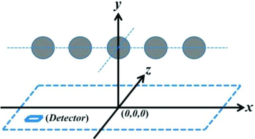
Our first numerical simulation is designed to test the geometry and the contour of cross sectional images. The phantom sample contains five uniform spherical absorbers, which are arranged on a plane with a distance of 15.0 mm to the detection plane (Fig. 1). Each spherical absorber has a radius of 1.5 mm. The center positions of the absorbers are at (−18.0, 0.0, 15.0), (−9.0, 0.0, 15.0), (0.0, 0.0, 15.0), (9.0, 0.0, 15.0), and (18.0, 0.0, 15.0) in a unit of mm, respectively. The relative intensities per unit volume are 1.0, 2.0, 3.0, 4.0, and 5.0 for the absorbers counted from left to right, respectively. In this simulation, we assume that a rectangular-shaped detector moves in a plane along both x- and y-axis from −30.0 to 30.0 mm with a spatial sampling period of 2/3 mm. Therefore, the photoacoustic signals are collected at 8281 (91 × 91) total positions. We also chose a small number of pixels (i.e., only 91 pixels × 91 pixels) for the cross-sectional reconstructed image in our numerical simulation to test if our FBP algorithm can still generate a high quality image even under poor measurement conditions. The detected area of 45.0 × 45.0 mm for the total pixel numbers used corresponds to a spatial resolution of 0.495 mm/pixel.
FIG. 1.
Geometry of the phantom sample used for the first simulation. Details can be found in the text.
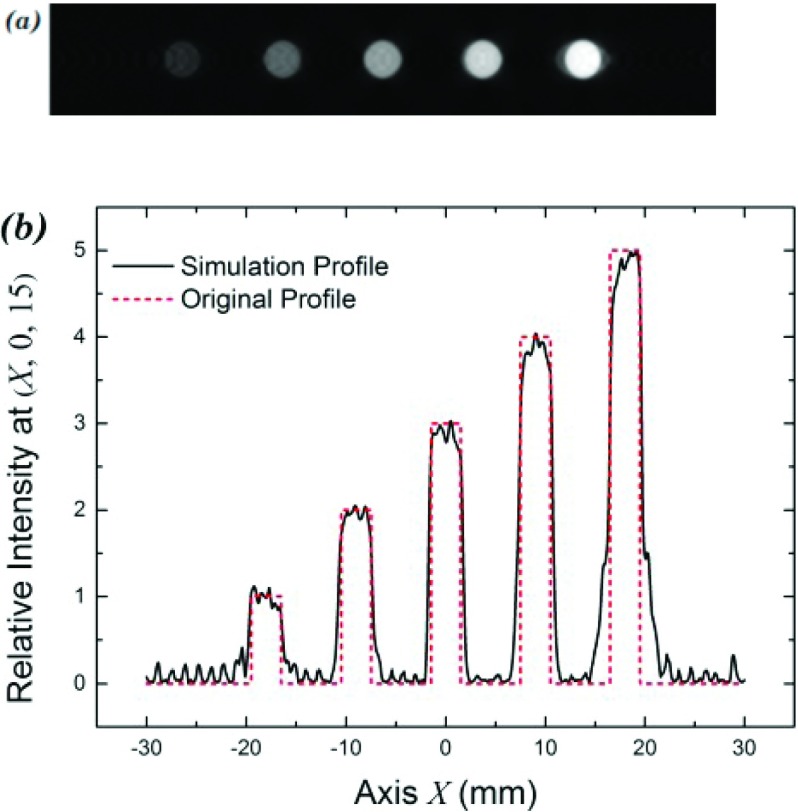
A cross section of a reconstructed image is shown in Fig. 2(a). We can see that this new approach allows us obtaining not only a sharp image [Fig. 2(a)] but also correct signal strength from the absorbers that well matches with the values of the absorption assumed for each absorber [Fig. 2(b)].
FIG. 2.
The first simulation for our back-projection algorithm. (a) Reconstructed image at the plane z = 15.0 mm; (b) relative intensities of the absorbers in the reconstructed image at a cross section plan (x,0,15).
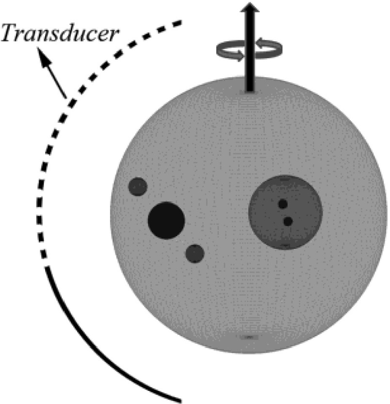
In our second numerical simulation, we designed a phantom sample containing absorbers with different sizes and overlapping areas, as shown in Fig. 3. We want to evaluate the performance of the new FBP algorithm for this complicated geometry. In addition, we also add a noise source to the observed signals to mimic more realistic experimental conditions. In details, the configuration of the second model is as follows: seven spherical absorbers are arranged in a way as shown in Fig. 3. Their center positions are at (0.0, 0.0, 0.0), (−4.0, 0.0, 0.0), (−4.0, 2.0, 0.0), (−4.0, −2.0, 0.0), (9.0, 0.0, 0.0), (11.0, −8.0, 0.0), and (7.0, 8.0, 0.0), respectively, where the coordinate unit is millimeter. Sphere 1 contains the other six spherical absorbers, while sphere 2 further contains spheres 3 and 4. The seven spherical absorbers have a radius of 15.0, 4.0, 0.5, 0.5, 2.0, 1.0, and 1.0 mm, respectively. For sphere 1, the intensity per unit volume is 1.0 except for the overlapping area. Sphere 2 has intensity per unit volume of 2.0 except for the overlapping area. For spheres 3, 4, 5, 6, and 7, the intensity per unit volume is 3.0, 3.0, 3.0, 2.0, and 2.0, respectively.
FIG. 3.
Geometry of absorbers for second simulation (details can be found in text).
The second measurement configuration is an arc-shaped detector array composed of 50-point detectors, evenly spaced over a span of 160°, with a radius of 65 mm. The detector array rotates in 2° steps over 360°, giving 9000 (50 × 180) detection points (see Fig. 3).
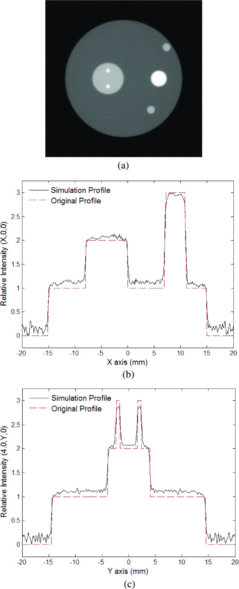
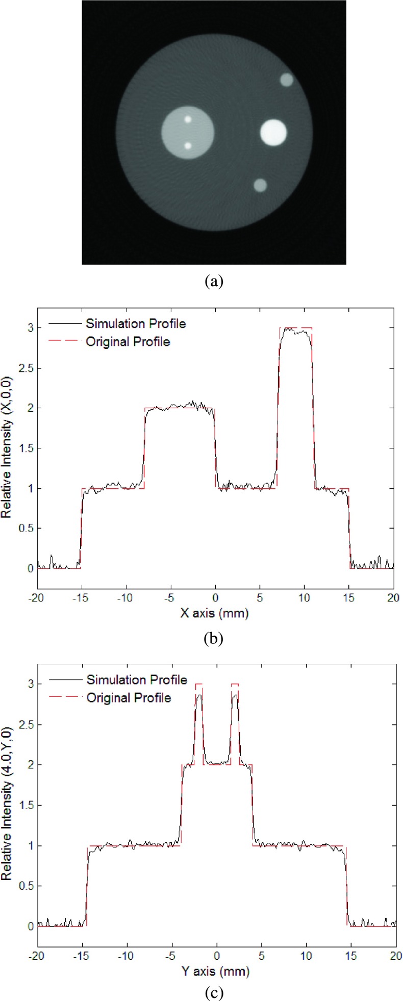
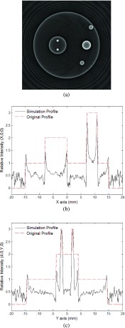
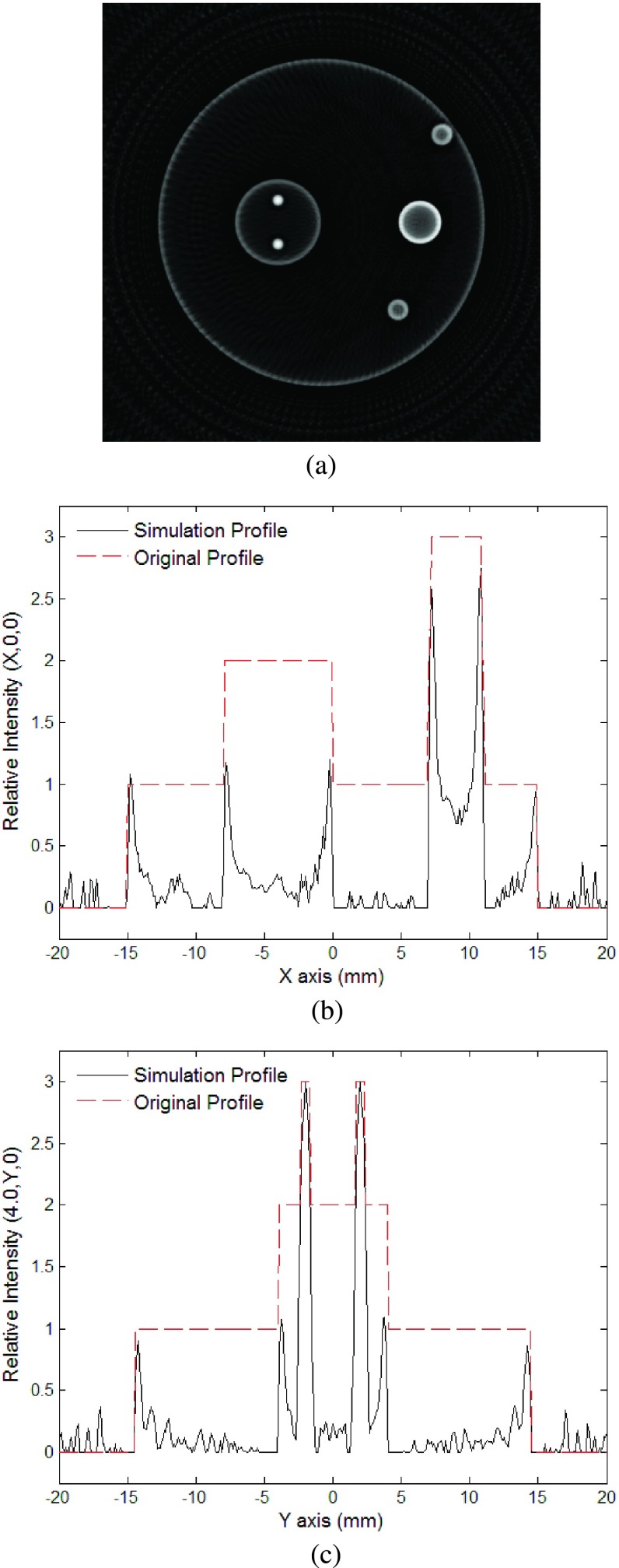
For the second model, we first performed the simulation of the phantom sample without noise. Figure 4(a) is a gray scale image of the reconstructed cross sectional image in the z = 0 mm plane. The reconstructed image is sharp enough and well represents the geometry of the absorbers. Although some small artificial structures can be seen around the reconstructed images of the absorbers, they are minimal and are mainly due to the limited detection angle and bandwidth. Figures 4(b) and 4(c) show a comparison of the intensities between the original and the reconstructed distributions along the lines at (x, 0, 0) and (−4, y, 0), respectively. The reconstructed intensity profiles are sharp and the values closely match with the original ones. Due to surrounding artifacts caused by the ringing effect, the intensity of the largest sphere was slightly higher than the initial intensity. This was mended by subtracting the average of the background from the image (Fig. 5). The high quality of the reconstructed images demonstrates the advantages of the new FBP algorithm, which benefits from the rigorously derived weighting function in the Fourier domain and an adaptive cutoff frequency, which differs from the usage of the filter functions in conventional FBP.
FIG. 4.
The second simulation without noise: (a) Reconstructed image using the new algorithm at plane z = 15.0 mm; (b) relative intensity of reconstructed image at (x, 0, 15); (c) relative intensity of reconstructed image at (−4, y, 15).
FIG. 5.
The second simulation without noise. After subtracting the background, the intensity well matches the original values of the model. (a) Reconstructed image using the new algorithm at plane z = 15.0 mm; (b) relative intensity of reconstructed image at (x, 0, 15); (c) relative intensity of reconstructed image at (−4, y, 15).
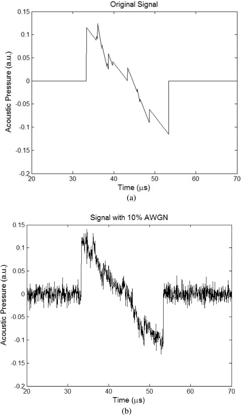
Next, we consider the case with additional noise in the measurements for the second model. From Eq. (16), we have (19), where the noise is 10% additive white Gaussian noise (AWGN), relative to maximum of each signal. Figure 6 gives an example of the time domain signal from a detector used for the simulations, where Fig. 6(a) shows an ideal signal without noise and Fig. 6(b) shows the signal with noise added,
| (19) |
FIG. 6.
An example of time domain signals from a detector used for the simulation. (a) Noiseless signal and (b) signal with 10% AWGN relative to the signal’s maximum.
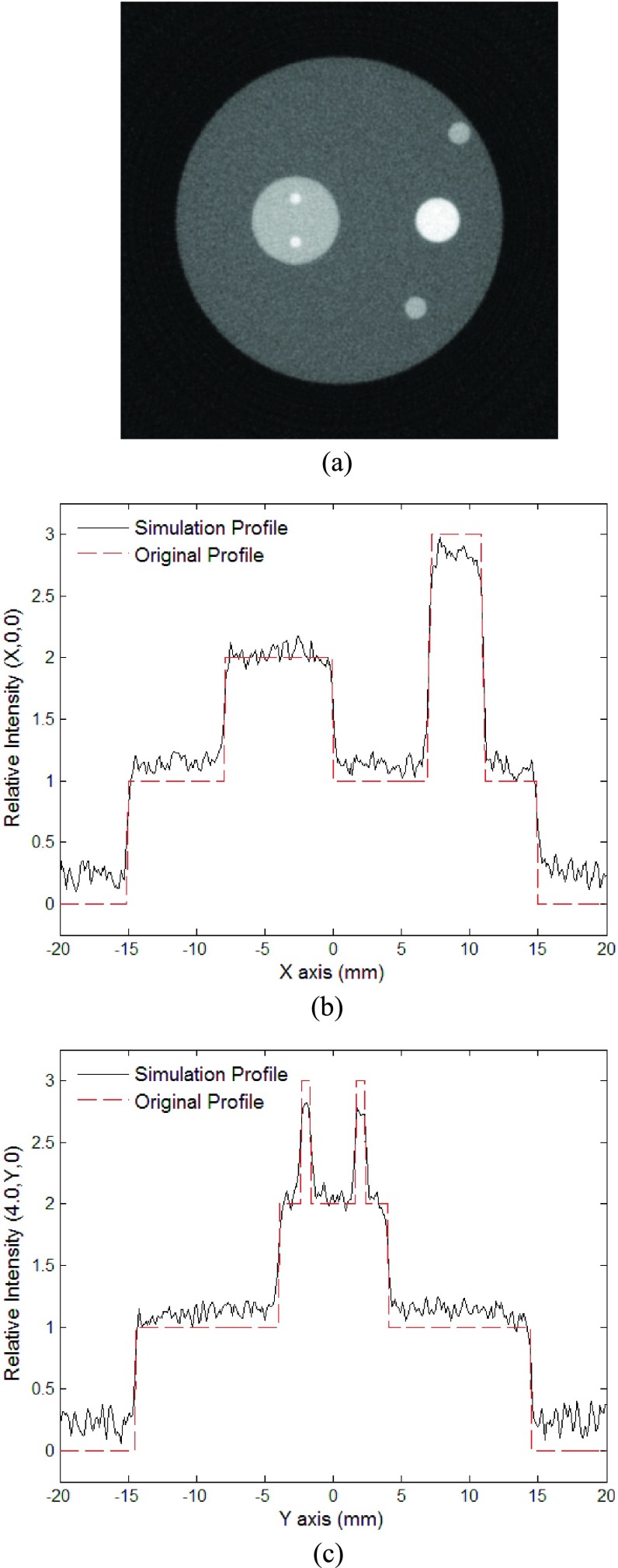
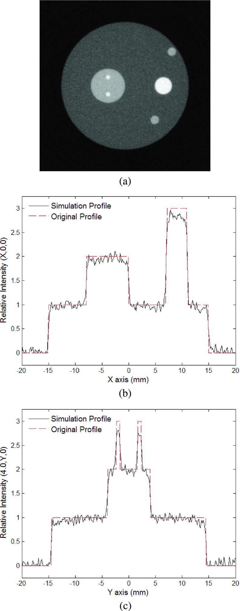
Figures 7(a) and 8(a) are reconstructed gray-scale images of the cross section of the absorbers in the z = 0 mm plane with noise introduced to the observed signals, where Fig. 8(a) is with the background subtracted. Although noise appears in the images, they are still clear enough to well present the geometry of the absorbers. Figures 7(b), 7(c), 8(b), and 8(c) show a comparison of the intensities between the original and the reconstructed intensity distributions along the lines (x, 0, 0) and (−4, y, 0). Despite the significant amount of noise, the reconstructed intensity profiles are still in good agreement with the original ones. The fact that the noise remains at a minimal level demonstrates the robustness of the new FBP algorithm for reconstructing PAT images of complicated structures with reasonable amount of detection noise.
FIG. 7.
The second simulation with noise added to the observed signals: (a) Reconstructed image using the new algorithm at plane z = 15.0 mm; (b) relative intensity of reconstructed image at (x, 0, 15); (c) relative intensity of reconstructed image at (−4, y, 15).
FIG. 8.
The second simulation with noise added to the observed signals and the background subtracted: (a) Reconstructed image using the new algorithm at plane z = 15.0 mm; (b) relative intensity of reconstructed image at (x, 0, 15); (c) relative intensity of reconstructed image at (−4, y, 15).
It is worth noticing that even under the assumed poor detection condition with a spatial resolution of 0.495 mm/pixel, the reconstructed image still well reproduces the geometry of the smallest absorbers, i.e., sphere 3 and sphere 4 with a radius of 0.5 mm for the cases either without (Figs. 4 and 5) or with detection noise (Figs. 7 and 8). In comparison, the results of utilizing a Hanning Window, with a cutoff frequency of 4 MHz, indicate that the image boundaries are well displayed but information of intensity is lost within the spheres (Figs. 9 and 10).
FIG. 9.
Simulation with Hanning window applied to noiseless signals: (a) Reconstructed image using the new algorithm at plane z = 15.0 mm; (b) relative intensity of reconstructed image at (x, 0, 15); (c) relative intensity of reconstructed image at (−4, y, 15).
FIG. 10.
Simulation with Hanning window applied to noiseless signals and the background subtracted: (a) Reconstructed image using the new algorithm at plane z = 15.0 mm; (b) relative intensity of reconstructed image at (x, 0, 15); (c) relative intensity of reconstructed image at (−4, y, 15).
5. CONCLUSIONS
In this paper, we have developed an improved FBP algorithm for PAT image reconstruction. We obtained an exact form of a weighting function from the basic photoacoustic wave equation. The weighting function serves as a precise ramp filter for processing the observed signals in the Fourier domain. Utilizing the weighting function, one can precisely calculate the contribution of the measured signals in Fourier domain. In addition, we also obtained an adaptive criterion to determine the cutoff frequency for the low-pass filter in Fourier domain. These new approaches allow us to obtain a sharper image. For fast numerical modeling, based on traceless, totally symmetric Cartesian tensors, we have introduced the ACE method to create the pressure model for simulating photoacoustic signals. In addition, our image reconstruction method utilizes the retarded potential generated by photoacoustic sources. We conducted numerical simulations on different phantom samples and demonstrated the effectiveness and robustness of our new FBP image reconstruction method. High quality reconstructed images were achieved using this algorithm, which have sharp borders and precise relative absorbed energy, even for complicated sample structures and with introduced noise in the observed signals.
ACKNOWLEDGMENTS
The authors gratefully acknowledge the Grant Support No. RP120558 from the Cancer Prevention Research Institute of Texas. This work is also partly supported by NIH R21EB008765.
APPENDIX A: WEIGHTING FUNCTION
Photoacoustic wave Eq. (2) has a general solution that can be expressed as,26
| (A1) |
where , i.e., Green’s function.
In order to further derive the solution for the photoacoustic wave equation, we first utilize the following mathematics substitution: and .
We then obtain
| (A2) |
From the inverse Fourier transform of Green’s function, we also have
| (A3) |
For the frequency axis, we can see that there are two simple poles when ω = ± ck because
| (A4) |
For t > 0, we can calculate the integration based on Cauchy’s residue theorem,54
| (A5) |
Hence, we have
| (A6) |
The pressure distribution function p(r, t) can be further derived by utilizing the above equation. We have
| (A7) |
We know that
| (A8) |
Comparing Eqs. (A7) and (A8), we obtain in Fourier space that
| (A9) |
Therefore, the initial pressure source function in time domain can be expressed as
| (A10) |
where is the weighting function, which represents the amount of contributions from a signal for the image reconstruction in the Fourier domain.
APPENDIX B: ACCELERATED CARTESIAN EXPANSIONS
1. Multipole expansion
The total potential at any point r ∈ ΩO due to k sources qi, i = 1, …, k located at points ri ∈ ΩS is given as
| (B1) |
where M(n) is the totally symmetric multipole tensor about the origin rS = {0, 0, 0}.
2. Multipole-to-multipole expansion
Given a multipole expansion of k sources about the rS = {0, 0, 0},
| (B2) |
where O(n) is old multipole tensor and P(m, n) is the permutation of all partitions of n into sets n − m and m.
3. Multipole to local translation
Assume that the domains ΩS and ΩO are sufficiently separated, and the distance between their centers rOS = |rS − rO| is greater that diam {ΩS} and diamf {ΩO}. If a multipole expansion M(n) is located at rS, then another expansion L(n) that produces the same field ∀r ∈ ΩO is given by
| (B3) |
where ρ = r − rO.
4. Local to local expansion
A local expansion O(n) that exists in the domain ΩO centered around rO can be shifted to the domain ΩO centered at rO using
| (B4) |
where rC = rO − rO.
5. Local to source
Finally, the potential at any point in the ΩO can be obtained using
| (B5) |
where ρoi = r − rO.
REFERENCES
- 1.Zhang H., Maslov K., Stoica G., and Wang L., “Functional photoacoustic microscopy for high-resolution and noninvasive in vivo imaging,” Nat. Biotechnol. 24(7), 848–851 (2006). 10.1038/nbt1220 [DOI] [PubMed] [Google Scholar]
- 2.Yakovlev V., Zhang H., Noojin G., Denton M., Thomas R., and Scully M., “Stimulated Raman photoacoustic imaging,” Proc. Natl. Acad. Sci. U. S. A. 107(47), 20335–20339 (2010). 10.1073/pnas.1012432107 [DOI] [PMC free article] [PubMed] [Google Scholar]
- 3.Kruger R. A., Liu P. Y., Fang Y. R., and Appledorn C. R., “Photoacoustic ultrasound (Paus) - Reconstruction tomography,” Med. Phys. 22(10), 1605–1609 (1995). 10.1118/1.597429 [DOI] [PubMed] [Google Scholar]
- 4.Esenaliev R. O., Karabutov A. A., Tittel F. K., Fornage B. D., Thomsen S. L., Stelling C., and Oraevsky A. A., “Laser optoacoustic imaging for breast cancer diagnostics: Limit of detection and comparison with x-ray and ultrasound imaging,” Proc. SPIE 2979, 71–82 (1997). 10.1117/12.280213 [DOI] [Google Scholar]
- 5.Hoelen C. G. A., de Mul F. F. M., Pongers R., and Dekker A., “Three-dimensional photoacoustic imaging of blood vessels in tissue,” Opt. Lett. 23(8), 648–650 (1998). 10.1364/ol.23.000648 [DOI] [PubMed] [Google Scholar]
- 6.Oraevsky A. A., Andreev V. A., Karabutov A. A., Fleming D. R., Gatalica Z., Singh H., and Esenaliev R. O., “Laser optoacoustic imaging of the breast: Detection of cancer angiogenesis,” Proc. SPIE 3597, 352–363 (1999). 10.1117/12.356829 [DOI] [Google Scholar]
- 7.Kruger R. A., Miller K., Reynolds H. E., Kiser W. L., Reinecke D. R., and Kruger G. A., “Breast cancer in vivo: Contrast enhancement with thermoacoustic CT at 434 MHz-feasibility study,” Radiology 216, 279–283 (2000). 10.1148/radiology.216.1.r00jl30279 [DOI] [PubMed] [Google Scholar]
- 8.Ku G. and Wang L. H. V., “Scanning thermoacoustic tomography in biological tissue,” Med. Phys. 27(5), 1195–1202 (2000). 10.1118/1.598984 [DOI] [PubMed] [Google Scholar]
- 9.Beard P. C., “Photoacoustic imaging of blood vessel equivalent phantoms,” Proc. SPIE 4618, 54–62 (2002). 10.1117/12.469848 [DOI] [Google Scholar]
- 10.Beard P., “Biomedical photoacoustic imaging,” Interface Focus 1(4), 602–631 (2011). 10.1098/rsfs.2011.0028 [DOI] [PMC free article] [PubMed] [Google Scholar]
- 11.Wang X., Pang Y., Ku G., Xie X., Stoica G., and Wang L. V., “Noninvasive laser-induced photoacoustic tomography for structural and functional in vivo imaging of the brain,” Nat. Biotechnol. 21(7), 803–806 (2003). 10.1038/nbt839 [DOI] [PubMed] [Google Scholar]
- 12.Razansky D. and Ntziachristos V., “Hybrid photoacoustic fluorescence molecular tomography using finite-element-based inversion,” Med. Phys. 34(11), 4293–4301 (2007). 10.1118/1.2786866 [DOI] [PubMed] [Google Scholar]
- 13.Razansky D., Vinegoni C., and Ntziachristos V., “Multispectral photoacoustic imaging of fluorochromes in small animals,” Opt. Lett. 32(19), 2891–2893 (2007). 10.1364/ol.32.002891 [DOI] [PubMed] [Google Scholar]
- 14.Kostli K. P., Frenz M., Bebie H., and Weber H. P., “Temporal backward projection of optoacoustic pressure transients using Fourier transform methods,” Phys. Med. Biol. 46(7), 1863–1872 (2001). 10.1088/0031-9155/46/7/309 [DOI] [PubMed] [Google Scholar]
- 15.Wang L. V., Photoacoustic Imaging and Spectroscopy (CRC, Boca Raton, 2009). [Google Scholar]
- 16.Ntziachristos V., “Clinical translation of optical and optoacoustic imaging,” Philos. Trans. R. Soc., A 369(1955), 4666–4678 (2011). 10.1098/rsta.2011.0270 [DOI] [PubMed] [Google Scholar]
- 17.Beard P. C. and Mills T. N., “An optical detection system for biomedical photoacoustic imaging,” Proc. SPIE 3916, 100–109 (2000). 10.1117/12.386310 [DOI] [Google Scholar]
- 18.Razansky D., “Multispectral optoacoustic tomography-volumetric color hearing in real time,” IEEE J. Sel. Top. Quantum Electron. 18(3), 1234–1243 (2012). 10.1109/jstqe.2014.2298471 [DOI] [Google Scholar]
- 19.Modgil D. and La Riviere P. J., “Optimizing wavelength choice for quantitative optoacoustic imaging using the Cramer-Rao lower bound,” Phys. Med. Biol. 55(23), 7231–7251 (2010). 10.1088/0031-9155/55/23/004 [DOI] [PubMed] [Google Scholar]
- 20.Dean-Ben X. L., Ntziachristos V., and Razansky D., “Statistical optoacoustic image reconstruction using a-priori knowledge on the location of acoustic distortions,” Appl. Phys. Lett. 98(17), 171110 (2011). 10.1063/1.3564905 [DOI] [Google Scholar]
- 21.Dean-Ben X. L., Ntziachristos V., and Razansky D., “Artefact reduction in optoacoustic tomographic imaging by estimating the distribution of acoustic scatterers,” J. Biomed. Opt. 17(11), 110504 (2012). 10.1117/1.jbo.17.11.110504 [DOI] [PubMed] [Google Scholar]
- 22.Bauer A. Q., Nothdurft R. E., Erpelding T. N., Wang L. H. V., and Culver J. P., “Quantitative photoacoustic imaging: Correcting for heterogeneous light fluence distributions using diffuse optical tomography,” J. Biomed. Opt. 16(9), 096016 (2011). 10.1117/1.3626212 [DOI] [PMC free article] [PubMed] [Google Scholar]
- 23.Cox B., Laufer J. G., Arridge S. R., and Beard P. C., “Quantitative spectroscopic photoacoustic imaging: A review,” J. Biomed. Opt. 17(6), 061202 (2012). 10.1117/1.jbo.17.6.061202 [DOI] [PubMed] [Google Scholar]
- 24.Dean-Ben X. L., Ntziachristos V., and Razansky D., “Acceleration of optoacoustic model-based reconstruction using angular image discretization,” IEEE Trans. Med. Imaging 31(5), 1154–1162 (2012). 10.1109/tmi.2012.2187460 [DOI] [PubMed] [Google Scholar]
- 25.Rosenthal A., Razansky D., and Ntziachristos V., “Fast semi-analytical model-based acoustic inversion for quantitative optoacoustic tomography,” IEEE Trans. Med. Imaging 29(6), 1275–1285 (2010). 10.1109/tmi.2010.2044584 [DOI] [PubMed] [Google Scholar]
- 26.Gateau J., Caballero M. A. A., Dima A., and Ntziachristos V., “Three-dimensional optoacoustic tomography using a conventional ultrasound linear detector array: Whole-body tomographic system for small animals,” Med. Phys. 40(1), 013302 (11pp.) (2013). 10.1118/1.4770292 [DOI] [PubMed] [Google Scholar]
- 27.Brecht H. P., Su R., Fronheiser M., Ermilov S. A., Conjusteau A., and Oraevsky A. A., “Whole-body three-dimensional optoacoustic tomography system for small animals,” J. Biomed. Opt. 14(6), 064007 (2009). 10.1117/1.3259361 [DOI] [PMC free article] [PubMed] [Google Scholar]
- 28.Ma R., Distel M., Dean-Ben X. L., Ntziachristos V., and Razansky D., “Non-invasive whole-body imaging of adult zebrafish with optoacoustic tomography,” Phys. Med. Biol. 57(22), 7227–7237 (2012). 10.1088/0031-9155/57/22/7227 [DOI] [PubMed] [Google Scholar]
- 29.Rosenthal A., Razansky D., and Ntziachristos V., “High-sensitivity compact ultrasonic detector based on a pi-phase-shifted fiber Bragg grating,” Opt. Lett. 36(10), 1833–1835 (2011). 10.1364/ol.36.001833 [DOI] [PubMed] [Google Scholar]
- 30.Morris P., Hurrell A., Shaw A., Zhang E., and Beard P., “A Fabry–Perot fiber-optic ultrasonic hydrophone for the simultaneous measurement of temperature and acoustic pressure,” J. Acoust. Soc. Am. 125(6), 3611–3622 (2009). 10.1121/1.3117437 [DOI] [PubMed] [Google Scholar]
- 31.Finch D., Patch S. K., and Rakesh , “Determining a function from its mean values over a family of spheres,” SIAM J. Math. Anal. 35(5), 1213–1240 (2004). 10.1137/s0036141002417814 [DOI] [Google Scholar]
- 32.Kunyansky L. A., “Explicit inversion formulae for the spherical mean Radon transform,” Inverse Probl. 23(1), 373–383 (2007). 10.1088/0266-5611/23/1/021 [DOI] [Google Scholar]
- 33.Xu Y., Xu M. H., and Wang L. H. V., “Exact frequency-domain reconstruction for thermoacoustic tomography - II: Cylindrical geometry,” IEEE Trans. Med. Imaging 21(7), 829–833 (2002). 10.1109/tmi.2002.801171 [DOI] [PubMed] [Google Scholar]
- 34.Kruger R. A., Lam R. B., Reinecke D. R., Del Rio S. P., and Doyle R. P., “Photoacoustic angiography of the breast,” Med. Phys. 37(11), 6096–6100 (2010). 10.1118/1.3497677 [DOI] [PMC free article] [PubMed] [Google Scholar]
- 35.Xu M. H. and Wang L. V., “Universal back-projection algorithm for photoacoustic computed tomography (vol. 71, art no 016706, 2005),” Phys. Rev. E 75(5), 059903 (2007). 10.1103/physreve.75.059903 [DOI] [PubMed] [Google Scholar]
- 36.Xu M. H. and Wang L. H. V., “Universal back-projection algorithm for photoacoustic computed tomography,” Phys. Rev. E 71(1), 016706 (2005). 10.1103/physreve.71.016706 [DOI] [PubMed] [Google Scholar]
- 37.Xu M. H. and Wang L. V., “Universal back-projection algorithm for photoacoustic computed tomography,” Proc. SPIE 5697, 251–254 (2005). 10.1117/12.589146 [DOI] [PubMed] [Google Scholar]
- 38.Wang X. D., Xu Y., Xu M. H., Yokoo S., Fry E. S., and Wang L. H. V., “Photoacoustic tomography of biological tissues with high cross-section resolution: Reconstruction and experiment,” Med. Phys. 29(12), 2799–2805 (2002). 10.1118/1.1521720 [DOI] [PubMed] [Google Scholar]
- 39.Kuchment P. and Kunyansky L., “A survey in mathematics for industry mathematics of thermoacoustic tomography,” Eur. J. Appl. Math. 19, 191–224 (2008). 10.1017/s0956792508007353 [DOI] [Google Scholar]
- 40.Kuchment P. and Kunyansky L., “Mathematics of photoacoustic and thermoacoustic tomography,” in Handbook of Mathematical Methods in Imaging, edited by Scherzer O. (Springer-Verlag, NY, 2011), pp. 817–866. [Google Scholar]
- 41.Norton S. J. and Linzer M., “Ultrasonic reflectivity imaging in 3 Dimensions - Exact inverse scattering solutions for plane, cylindrical, and spherical apertures,” IEEE Trans. Biomed. Eng. 28(2), 202–220 (1981). 10.1109/tbme.1981.324791 [DOI] [PubMed] [Google Scholar]
- 42.Kunyansky L. A., “A series solution and a fast algorithm for the inversion of the spherical mean Radon transform,” Inverse Probl. 23(6), S11–S20 (2007). 10.1088/0266-5611/23/6/s02 [DOI] [Google Scholar]
- 43.Lam R. B., Kruger R. A., Reinecke D. R., DelRio S. P., Thornton M. M., Picot P. A., and Morgan T. G., “Dynamic optical angiography of mouse anatomy using radial projections,” Proc. SPIE 7564, 756405 (2010). 10.1117/12.841024 [DOI] [Google Scholar]
- 44.Razansky D., Distel M., Vinegoni C., Ma R., Perrimon N., Koster R. W., and Ntziachristos V., “Multispectral opto-acoustic tomography of deep-seated fluorescent proteins in vivo,” Nat. Photonics 3(7), 412–417 (2009). 10.1038/nphoton.2009.98 [DOI] [Google Scholar]
- 45.Paltauf G. and Dyer P. E., “Photomechanical processes and effects in ablation,” Chem. Rev. 103(2), 487–518 (2003). 10.1021/cr010436c [DOI] [PubMed] [Google Scholar]
- 46.Huang H. and Ye J. Y., “A precise time-domain backprojection approach for photoacoustic image reconstruction,” Patent pending, Serial Number: 14/577,960 (2014).
- 47.Landau L. D. and Lifshitz E. M., Fluid Mechanics, 2nd ed. (Butterworth-Heinemann, London, Oxford, UK, 1987). [Google Scholar]
- 48.Liu P., “Recent developments in photoacoustic image reconstruction,” Proc. SPIE 3254, 325–330 (1998). 10.1117/12.308180 [DOI] [Google Scholar]
- 49.Xu M. H. and Wang L. H. V., “Photoacoustic imaging in biomedicine,” Rev. Sci. Instrum. 77(4), 041101 (2006). 10.1063/1.2195024 [DOI] [Google Scholar]
- 50.Huang H. and Balasubramaniam S., “Cartesian harmonics and fast computation of potentials of the form r−v,” Presented at the 2006 URSI Meeting-CNC/USNC, Albuquerque, NM (2006).
- 51.Huang H. and Balasubramaniam S., “Accelerated cartesian expansion based method for rapidly computing the shielded coulomb potential,” Presented at the 2007 URSI Meeting-CNC/USNC, Ottawa, ON, Canada (2007).
- 52.Shanker B. and Huang H., “Accelerated cartesian expansions - A fast method for computing of potentials of the form R-v for all real v,” J. Comput. Phys. 226(1), 732–753 (2007). 10.1016/j.jcp.2007.04.033 [DOI] [Google Scholar]
- 53.Huang H. and Deng Y. M., “A novel and fast numerical technique for large-scale electromagnetic imaging systems,” IEEE Trans. Magn. 48(11), 2781–2784 (2012). 10.1109/tmag.2012.2198206 [DOI] [Google Scholar]
- 54.Jackson J. D., Classical Electrodynamics (Wiley, New York, NY, 1962). [Google Scholar]


