Abstract
In this report, we demonstrate a simple and low cost method that can be reproducibly used for fabrication of microfluidic devices in nitrocellulose. The fluidic patterns are created via a laser-based direct-write technique that induces polymerisation of a photo-polymer previously impregnated in the nitrocellulose. The resulting structures form hydrophobic barriers that extend through the thickness of the nitrocellulose and define an interconnected hydrophilic fluidic-flow pattern. Our experimental results show that using this method it is possible to achieve microfluidic channels with lateral dimensions of ∼100 μm using hydrophobic barriers that form the channel walls with dimensions of ∼60 μm; both of these values are considerably smaller than those that can be achieved with other current techniques used in the fabrication of nitrocellulose-based fluidic devices. A simple grid patterned nitrocellulose device was then used for the detection of C-reactive protein via a sandwich enzyme-linked immunosorbent assay, which served as a useful proof-of-principle experiment.
I. INTRODUCTION
In recent years, the requirements for simple, accurate, and low-cost diagnostic solutions in both developing and developed countries have led to a rapid progress in the fabrication of point-of-care (POC) devices. Microfluidic engineering technology has been widely used for implementing lab-on-chip (LOC) type point-of-care devices since its origins in the 1990s.1 One of the main reasons behind the use of this LOC-type microfluidic technique for POC diagnostics is the possibility of reducing the quantity of valuable samples or reagents that would be needed and also the possibility to shorten the detections times, which would result primarily from the compact structure and small size of such LOC devices. However, although this technology is promising and there have been a large number of achievements in this field, there is still a bottleneck in the development of commercialized products, which can be attributed to a disconnect between users, academic researchers, and manufacturers.2
This situation is changing, however, with the emergence of capillary-based microfluidic devices and, in particular, with the relatively recent adoption of paper, one of the most simple and widely used capillary structures. Paper as the functional substrate has already been widely researched as an alternative to other commonly used substrates such as glass, silicon, SU8, and PDMS (Polydimethylsiloxane), and many different kinds of microfluidic devices with a range of structures and applications have been reported.3 This is a direct result of the many advantages offered by paper, namely, its low cost, availability, ease of storage and transport, and finally being easily disposable in a non-hazardous manner. Paper-based fluidics, therefore, presents itself as a LOC technology that could become the technique of choice for mass-market commercialized POC diagnostic devices.
In addition, when compared with other solid-material-based LOC-type microfluidic devices, those based on porous paper do not require any additional pumps because of the inherent ability of paper to wick fluids via capillary forces. This provides a real advantage with regards to both the cost and manufacturability of any such device and has hence led to the development of many paper-based POC devices based on simple colorimetric bio-assays.3–5 In addition, porous nitrocellulose membranes, since their first demonstration in the 1960s, have been widely used, due to some key features, such as their smooth surface, uniform pore size, and high protein-binding capability.6 A large number of biological assays, namely, blotting assays, flow-through assays, and lateral flow tests have been developed on these porous nitrocellulose membranes, and hence nitrocellulose-based microfluidic devices are currently regarded as the alternative of choice for improving the performance of existing POC assays.
Several methods have already been reported for fabricating fluidic patterns/devices in such materials, and these can be classified into two broad categories: 2D cutting/shaping and physical blocking of pores. The techniques so far reported include the use of photolithography,7 inkjet printing,8,9 printing of wax,10,11 plasma oxidation,12,13 laser-cutting,14 and shaping,15 each of which has its own merits and drawbacks. In general, the ideal technique should be as simple, cheap, and fast to implement as possible, and therefore multiple printing steps, the use of specialist chemicals, or complex post-processing procedures are to be avoided. The other factor is the feature sizes achievable, which is where procedures such as plotting or wax printing may present restrictions in this context.
Here, we report a new concept to pattern nitrocellulose membranes for low-cost microfluidic devices. We employ a laser-based direct-write (LDW) procedure to create fluidic patterns using the concept of light-induced photo-polymerisation. The fluidic channel patterns are formed by hydrophobic photo-polymer barriers that demarcate the flow regions within the hydrophilic paper. In contrast to the most widely used methods for patterning paper, our approach not only eliminates the requirements for cleanroom-based steps, expensive masks, specialist reagents, and custom-designed equipment, but is also amenable to large-scale commercialization. Since LDW is a non-contact procedure, it minimizes any chances of cross-contamination, an essential criterion in fabrication of microfluidic devices for biological and biomedical applications. As shown later, using this approach, we have successfully demonstrated that it is possible to create microfluidic channels with barrier-walls that have dimensions of ∼60 μm—a size which has not yet been achieved using other reported methods. Finally, this LDW process is also suitable for a roll-to-roll process, and we believe that this technique presents itself as a promising methodology that can be used for fabricating nitrocellulose-based POC devices.
II. EXPERIMENTAL SECTION
A. Laser setup and materials
The laser used for our LDW patterning process was a 405 nm continuous wave (c.w.) diode-laser (Cobolt MLD, Cobolt AB, Sweden) with a maximum output power of ∼110 mW.
The substrates used were Protran® nitrocellulose membranes BA85 from Whatman, USA, and the photo-polymer used was DeSolite® 3471‐3-14 from DSM Desotech, Inc., USA. For this specific photopolymer, the fluence required (for 90% curing) is ∼0.4 J/cm2. By varying both the laser scan speed and the laser power, a range of experiments was performed in order to find the optimum conditions for forming fluidic structures.
B. Methods
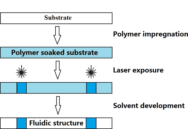
Paper-based microfluidic devices were fabricated by creating hydrophobic barriers in the nitrocellulose membranes via the effect of light-induced photo-polymerisation. The LDW technique we use to create fluidic patterns is described as follows (Figure 1). A laser beam is first scanned across the nitrocellulose membrane which has been pre-soaked with a light-sensitive photo-polymer (DeSolite) which induces light-induced cross-linking of the photo-polymer along the exposed regions. This laser-scanned substrate is then developed in a solvent to wash away any un-polymerised material, leaving behind a user-defined pattern of polymerised photo-polymer in the laser-exposed regions. These polymerised barriers extend throughout the thickness of the substrate and serve as hydrophobic barrier-walls that can contain and guide liquids introduced onto the substrate.
FIG. 1.
Schematic of the LDW-based paper-patterning procedure.
As the extent of the photo-polymerisation process is directly dependent on the incident laser fluence, the widths, depths, and the quality of polymerised patterns can be easily controlled by changing the fluence along the exposed area. Thus, any desired fluidic pattern can be produced by simply modifying the laser exposure parameters during the LDW process via the laser scan speed and/or laser power.
C. Procedure
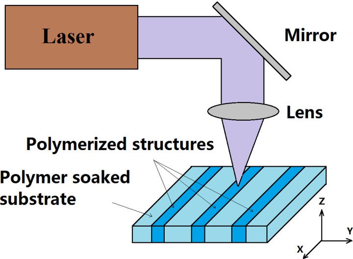
As shown in the schematic in Figure 2, during the first LDW step, the laser beam is focused onto the nitrocellulose substrate using a spherical lens (f = 15 cm). The substrate was mounted on an xyz-stage, and by controlling the positions in the x and y directions, a user-defined 2D design is patterned on the substrate. The third axis, z, was used to position the substrate at the optimum position (usually, at the focal plane of the lens). For experiments performed in this report, the nitrocellulose substrates were positioned at the focal point, and the corresponding laser spot diameter was ∼8 μm, and the Rayleigh range was ∼125 μm. The range of substrate translational speeds trialled varied from 0.05 mm/s to 10 mm/s, while the incident average powers ranged from 0.3 mW through 10 mW. The corresponding incident fluences can hence be calculated using the equation:
which, therefore, ranged from ∼0.375 J/cm2 to ∼2500 J/cm2.
FIG. 2.
Schematic of the laser-based direct-write process used to form polymerised hydrophobic structures in paper.
The final developing step was to wash off any un-polymerised photo-polymer from the substrate through immersion in a suitable solvent (in this case toluene), which does not affect the intentionally polymerised regions.
III. RESULTS AND DISCUSSION
The choice of an appropriate photo-polymer that does not alter the properties of the nitrocellulose substrates is vital, and several, such as SubG from Maker Juice, USA, Norland 61 & 68 from Norland Products, Inc., USA, and Ablelux A4061T & A4086 from Henkel AG & Co., Germany, were tested in order to find the most suitable. Specifically, photo-polymers that reacted with the nitrocellulose substrate and either dissolved or decomposed it, visibly degraded it, or transformed it into an extremely hydrophobic “plastic-like” material were rejected. Our current choice, DeSolite is, however, extremely viscous, having a viscosity of ∼10 000 mPa s at 25 °C, and so we diluted it in toluene in the ratio of 5:3 (v/v) to enable it to soak into the nitrocellulose substrates. These were then left to dry under ambient laboratory conditions, prior to the laser-patterning step.
A. Writing of fluidic channels
The first structures to be investigated were simple straight-line channels which would allow determination of some of the basic parameters of laser exposure (scan speed and laser power) required. As shown in Figure 3(a), two parallel channels were written by scanning at laser powers of 10 and 5 mW under the same scan speed of 10 mm/s, and the fluid containing properties of these channels was tested by flowing red ink (Parker, France) through them. As can be seen in Figure 3(b), the scanned lines form the barrier walls that contain and guide the flow of red ink through these fluidic channels without any observed sideways leakage.
FIG. 3.

Images showing two fluidic channels formed by writing parallel lines with two different laser powers of 10 and 5mW at a speed of 10 mm/s.
Because toluene is volatile and easily evaporates under ambient laboratory conditions, it proved difficult to uniformly soak the substrates with the photo-polymer. As the width, depth, and uniformity of the polymerised lines are directly dependent on the polymer concentration in the substrate, any variations would thus translate into lines having undesirable variations. To circumvent this, we chose to soak the nitrocellulose paper directly with the undiluted photo-polymer. However, due to its high viscosity it took ∼20 s for the paper to fully absorb the photo-polymer.
Figure 4 shows a nitrocellulose substrate that has undergone LDW to polymerise a set of parallel lines, written with different scan speeds (0.05, 0.1, 0.5, 1, 5, and 10 mm/s) but with a fixed laser power of 10 mW. The lines shown, after development in toluene, appear as transparent regions of the otherwise white nitrocellulose substrate. This relatively good level of optical transparency of the lines within the otherwise scattering medium is as a result of the induced polymerisation. Lines written with a scan speed less than 5 mm/s have poor definition with irregular edges, which is the result of over-polymerisation due to the unnecessarily high exposures used. However, for scan speeds greater than 5 mm/s, we see that the lines are increasingly well-defined and, as shown in a subsequent figure, perform well as barriers to contain and guide fluids.
FIG. 4.
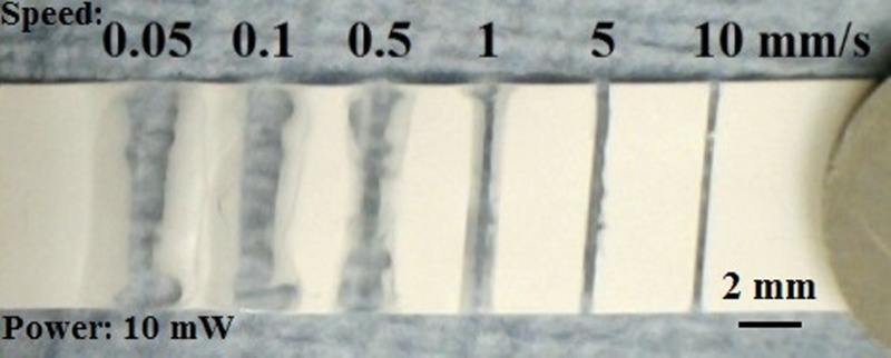
Photographic image showing a nitrocellulose substrate with a set of parallel lines that were polymerised using different scan speeds of 0.05–10 mm/s at an incident laser power of 10 mW.
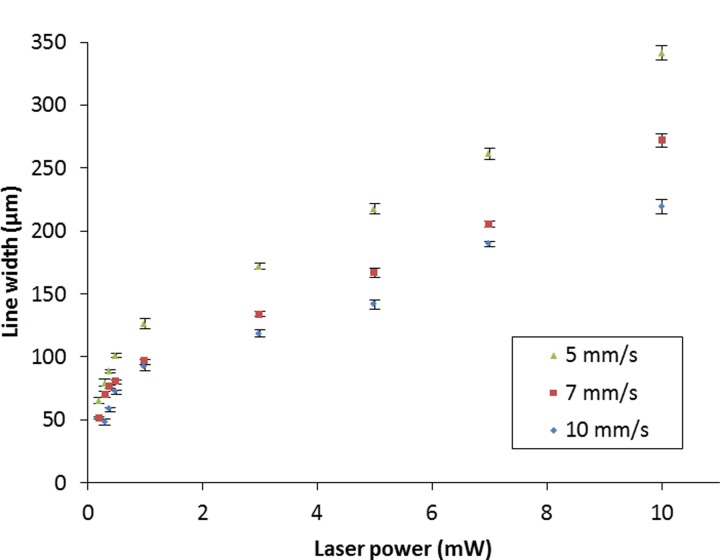
To further identify the optimum condition in terms of the width and the quality of the patterned lines, we performed a subsequent study by varying the laser power as well as the laser scan speed. The plots in Figure 5 show the relationship between the widths of the polymerised lines and the laser power for three different scan speeds. The line widths obtained increase from ∼70 μm and ∼50 μm to ∼340 μm and ∼270 μm at scan speeds of 5 mm/s and 7 mm/s, respectively, for an increase in the laser power from 0.2 mW to 10 mW. Similarly, for a scan speed of 10 mm/s, the widths of the polymerised lines increase from ∼50 μm to ∼220 μm as the laser power increases from 0.3 mW to 10 mW.
FIG. 5.
Plots showing the variations in the widths of the polymerised lines for different laser powers at three scan speeds. Error bars indicate the standard deviation for 5 measurements along each line.
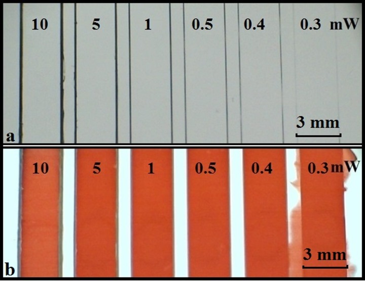
As our final goal was to pattern the nitrocellulose membranes for implementation of LOC fluidic devices, our aim was to identify the optimum conditions for the fabrication of fluidic channels that are able to reliably contain and guide the flow without leakage. Figure 6(a) shows a set of straight channels having a common width of 3 mm, written with a constant laser scan speed of 10 mm/s for varying laser powers ranging from 10 mW to 0.3 mW. Figure 6(b) is an image of the same set of channels after introduction of red ink into each channel. As can be seen from this figure, the ink solution only leaks out of the channel written with the lowest laser power of 0.3 mW, and all other channels contain and guide the flow without any leakage. Using the proposed LDW photo-polymerisation technique, the smallest size of barrier line, which we can form in nitrocellulose and which is able to contain and guide the flow, is ∼60 μm—the smallest dimensions reported in literature when compared with other techniques reportedly used to fabricate microfluidic devices such as photolithography, inkjet etching, and wax printing.16
FIG. 6.
(a) Image showing a set of fluidic channels formed with pairs of parallel polymerised barrier-walls that were written with different incident laser powers of 10–0.3 mW at a constant scan speed of 10 mm/s; (b) after introduction of red ink into each channel.
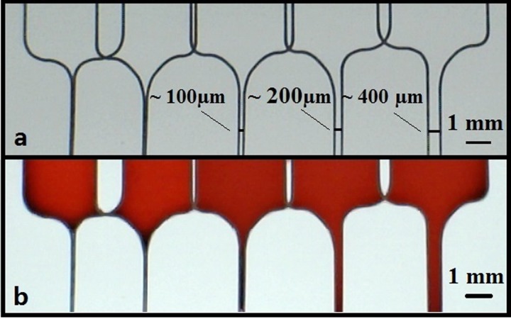
The final step was to determine the minimum width for a fluidic channel that can be patterned via LDW that will successfully allow fluid flow. While the typical widths achieved with the wax printing procedure, which is currently one of the most widely implemented techniques, ranges from 0.5 mm to 4 mm,17 we anticipated that our LDW technique could produce channel widths that might be around one order of magnitude lower. To identify the smallest widths such fluidic channels can have, as shown in Figure 7(a), we patterned several pairs of parallel lines with different channel widths which were fed by the open U-shaped structures that would form the fluid reservoirs for the ink used. All these lines were scanned at the same laser scan speed of 10 mm/s and an incident laser power of 1 mW, a condition we knew produced barrier-walls that reliably contained the fluid. As shown in Figure 7(b), after introduction of the ink, channels down to a width as small as ∼100 μm could reliably guide the fluid. This, to our knowledge, is the smallest dimension for any paper-patterned structures reported so far.16
FIG. 7.
Photographic image showing a set of parallel fluidic channels having different channel widths, patterned with a laser power of 1 mW, and a scan speed of 10 mm/s (a) before and (b) after introduction of 3 μl of red ink into the reservoirs at the top-end of each of these channels.
B. Writing of fluidic wells
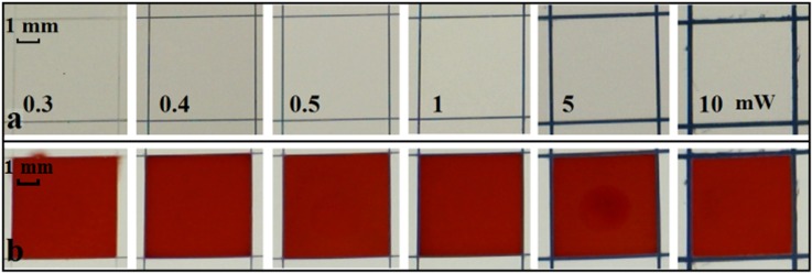
The second set of experiments relates to the writing of wells in paper and their ability to contain fluid. Figure 8(a) shows a set of square wells with dimensions of 5 mm × 5 mm with barrier-walls written using laser powers ranging from 0.3 mW to 10 mW at a fixed scan speed of 10 mm/s. Red ink was again introduced in a fixed volume of 3 μl that was sufficient to fill each square completely. As shown in Figure 8(b), we similarly observed leakage only for the wells written with a laser power of 0.3 mW, which we have determined to be the lower threshold value.
FIG. 8.
Photographic image showing (a) a series of 5 mm × 5 mm square-shaped wells patterned with different laser powers of 0.3, 0.4, 0.5, 1, 5, and 10 mW at a constant scanning speed of 10 mm/s; (b) after introduction of 3 μl of red ink into each square.
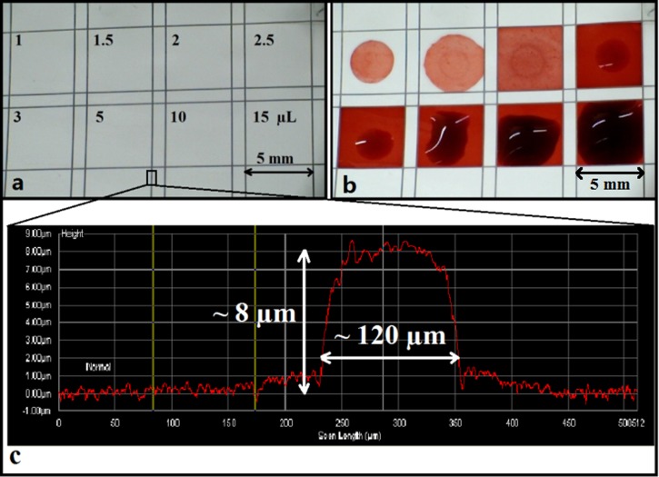
The final step was to determine the maximum volume of liquid that these wells could contain without any sideways leakage, a parameter which is important when dealing with actual samples under test, where loss of potentially expensive samples of reagents outside the test area must be avoided. A similar set of squares was written (shown in Figure 9(a)) into which red ink of different volumes ranging from 1 μl to 15 μl (Figure 9(b)) was introduced. Even when the volume increased to a value of 15 μl, the wells were still able to hold the ink solutions without any overflow.
FIG. 9.
Image showing (a) a series of 5 mm × 5 mm wells patterned with a laser power of 1 mW and a scan speed of 10 mm/s; (b) after introduction of red ink in different volumes of 1–15 μl into each square; (c) a surface-profiler scan across a polymerised barrier-wall.
On further investigation, we observed that a surface-relief ridge was formed along and above the patterned lines because of the polymerisation of the photopolymer that was present on the surface of the nitrocellulose membranes prior to the laser-patterning step and has been investigated through surface-profile imaging measurements. The trace in Figure 9(c) is a surface-profile scan across a laser-polymerised line and clearly shows the presence of a ridge (having a width of ∼120 μm and a height of ∼8 μm) along the polymerised line. Hence, it can be concluded that the polymerised patterns defined in nitrocellulose using the LDW method not only show excellent ability in containing small liquid volumes but also show the capability to contain larger liquid volumes without any undesired spill-over, a characteristic that is of immediate interest for practical diagnostic assays.
Following these characterization experiments, we chose to validate the effectiveness of our devices as sensors that can be used for the detection of CRP (C-reactive protein), which is an annular protein found in blood plasma and is mainly used as a marker of inflammation. Measuring and charting CRP levels can provide useful information in determining disease progress or the effectiveness of treatments. This experiment served as a useful proof-of-principle and we performed this detection via the sandwich ELISA (enzyme-linked immunosorbent assay), which is one of the most common reactions used for medical diagnostics.
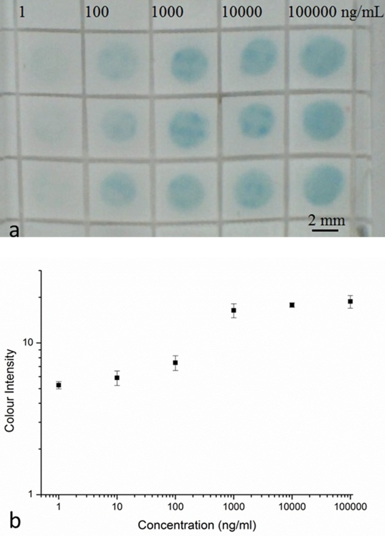
The grid pattern that formed the square-well detection zones was patterned at a laser power of 1 mW and a scan speed of 10 mm/s, as described earlier. The solution of mouse IgG primary antibody (2 μl at 360 μg/ml) was first pipetted into each square-well of the grid-like structure (as shown in Figure 10(a)) in the nitrocellulose paper, which was then left to dry at room temperature for at least 1 h. The whole paper-device was blocked using a blocking solution of 5% bovine serum albumin (BSA), in phosphate buffered saline (PBS) for 1 h. Following this, the device was washed 3 times with PBS. Sample solutions of CRP were prepared at dilutions of 1 ng/ml, 10 ng/ml, 100 ng/ml, 1000 ng/ml, 10 000 ng/ml, and 100 000 ng/ml. The samples (2 μl) were then pipetted on individual squares and were incubated for 1 h. Then, the device was washed again for 3 times with PBS and a solution of anti-human CRP antibody (2 μl at 22.5 μg/ml) was pipetted into each square-well. The whole device was again left for 1 h for incubation and this was followed by washing 3 times with PBS. In the next step, the HRP (horseradish peroxidase) conjugated streptavidin was added into each well and the device was left in the dark for 20 min of incubation and then washed again using PBS. Finally, the chromogenic reagent TMB (3,3′,5,5′-Tetramethylbenzidine) was pipetted on the whole device and the colour change produced was imaged by taking a photograph (as seen in Figure 10(a)) of the paper-device after 2 min with a USB camera.
FIG. 10.
(a) Selected area of 5 × 5 mm well structure patterned with a laser power of 1 mW and a scan speed of 10 mm/s and results for the detection of CRP by the sandwich ELISA. (b) Calibration curve constructed using the grayscale intensity values taken from the image shown in (a). Error bars indicate the standard deviation for 4 individual measurements.
The image was then processed with the ImageJ software (National Institutes of Health, USA) to extract the respective colour intensities of the blue colour produced within the square-well detection zones. The average grayscale intensities of each detection zone and of the background of the image were measured, and the background intensity was subtracted from the intensity of each detection zone to obtain the actual colour intensity of each spot to eliminate the influence of the background. By measuring the colour intensities of the known concentrations, we were then able to plot the curve (as seen in Figure 10(b)) that can then be used for calibration.
IV. CONCLUSION
We have demonstrated that a simple, low-cost laser-based direct-write technique based on the principle of light-induced polymerisation can be used for the rapid fabrication of fluidic structures in nitrocellulose membranes. The laser polymerised patterns form the hydrophobic barrier-walls of interconnected hydrophilic fluidic structures such as channels and wells. This approach is non-lithographic and mask-less, and being non-contact in nature, offers the advantage of minimizing cross-contamination that could arise during fabrication. Compared with other methods used in the production of microfluidic devices in nitrocellulose, the technique is also well-suited for up-scaling to mass-production. We have shown that using this method it is possible to create microfluidic channels and barrier-walls with dimensions of ∼100 μm and ∼60 μm, respectively, the smallest values that have been reported so far. We believe that this technique could be an ideal choice for rapid fabrication of nitrocellulose-based microfluidic devices that can be used for a variety of applications such as clinical diagnostics and analytical chemistry.
ACKNOWLEDGMENTS
The authors acknowledge the funding received via the Engineering and Physical Sciences Research Council (EPSRC) Grant Nos. EP/J008052/1 and EP/K023454/1, and the funding received via a Knowledge Mobilisation Fellowship for Dr. Collin Sones from the Institute for Life Sciences and the Faculty of Health Sciences of the University of Southampton.
References
- 1.Whitesides G. M., “ The origins and the future of microfluidics,” Nature 442, 368–373 (2006). 10.1038/nature05058 [DOI] [PubMed] [Google Scholar]
- 2.Whitesides G. M., “ Cool, or simple and cheap? Why not both?,” Lab Chip 13, 11–13 (2013). 10.1039/C2LC90109A [DOI] [PubMed] [Google Scholar]
- 3.Martinez A. W., Phillips S. T., Butte M. J., and Whitesides G. M., “ Patterned paper as a platform for inexpensive, low-volume, portable bioassays,” Angew. Chem., Int. Ed. 46, 1318–1320 (2007). 10.1002/anie.200603817 [DOI] [PMC free article] [PubMed] [Google Scholar]
- 4.Martinez A. W., Phillips S. T., Carrilho E., Thomas S. W., Sindi H., and Whitesides G. M., “ Simple telemedicine for developing regions: Camera phones and paper-based microfluidic devices for real-time, off-site diagnosis,” Anal. Chem. 80, 3699–3707 (2008). 10.1021/ac800112r [DOI] [PMC free article] [PubMed] [Google Scholar]
- 5.Lu Y., Shi W. W., Jiang L., Qin J. H., and Lin B. C., “ Rapid prototyping of paper-based microfluidics with wax for low-cost, portable bioassay,” Electrophoresis 30, 1497–1500 (2009). 10.1002/elps.200800563 [DOI] [PubMed] [Google Scholar]
- 6.Tonkinson J. L. and Stillman B. A., “ Nitrocellulose: A tried and true polymer finds utility as a post-genomic substrate,” Front. Biosci. 7, C1–C12 (2002). 10.2741/tonkins [DOI] [PubMed] [Google Scholar]
- 7.Martinez A. W., Phillips S. T., Wiley B. J., Gupta M., and Whitesides G. M., “ FLASH: A rapid method for prototyping paper-based microfluidic devices,” Lab Chip 8, 2146–2150 (2008). 10.1039/b811135a [DOI] [PMC free article] [PubMed] [Google Scholar]
- 8.Delaney J. L., Hogan C. F., Tian J. F., and Shen W., “ Electrogenerated chemiluminescence detection in paper-based microfluidic sensors,” Anal. Chem. 83, 1300–1306 (2011). 10.1021/ac102392t [DOI] [PubMed] [Google Scholar]
- 9.Li X., Tian J. F., Garnier G., and Shen W., “ Fabrication of paper-based microfluidic sensors by printing,” Colloid Surf. Bs 76, 564–570 (2010). 10.1016/j.colsurfb.2009.12.023 [DOI] [PubMed] [Google Scholar]
- 10.Carrilho E., Martinez A. W., and Whitesides G. M., “ Understanding wax printing: A simple micropatterning process for paper-based microfluidics,” Anal. Chem. 81, 7091–7095 (2009). 10.1021/ac901071p [DOI] [PubMed] [Google Scholar]
- 11.Leung V., Shehata A. A. M., Filipe C. D. M., and Pelton R., “ Streaming potential sensing in paper-based microfluidic channels,” Colloid Surf. A 364, 16–18 (2010). 10.1016/j.colsurfa.2010.04.008 [DOI] [Google Scholar]
- 12.Souza C. D., Braga O. C., Vieira I. C., and Spinelli A., “ Electroanalytical determination of sulfadiazine and sulfamethoxazole in pharmaceuticals using a boron-doped diamond electrode,” Sens. Actuator, B 135, 66–73 (2008). 10.1016/j.snb.2008.07.020 [DOI] [Google Scholar]
- 13.Li X., Tian J. F., Nguyen T., and Shen W., “ Paper-based microfluidic devices by plasma treatment,” Anal. Chem. 80, 9131–9134 (2008). 10.1021/ac801729t [DOI] [PubMed] [Google Scholar]
- 14.Fu E., Kauffman P., Lutz B., and Yager P., “ Chemical signal amplification in two-dimensional paper networks,” Sens. Actuator, B 149, 325–328 (2010). 10.1016/j.snb.2010.06.024 [DOI] [PMC free article] [PubMed] [Google Scholar]
- 15.Fenton E. M., Mascarenas M. R., Lopez G. P., and Sibbett S. S., “ Multiplex lateral-flow test strips fabricated by two-dimensional shaping,” ACS Appl. Mater. Interfaces 1, 124–129 (2009). 10.1021/am800043z [DOI] [PubMed] [Google Scholar]
- 16.Yetisen A. K., Akram M. S., and Lowe C. R., “ Paper-based microfluidic point-of-care diagnostic devices,” Lab Chip 13, 2210–2251 (2013). 10.1039/c3lc50169h [DOI] [PubMed] [Google Scholar]
- 17.Li X., Ballerini D. R., and Shen W., “ A perspective on paper-based microfluidics: Current status and future trends,” Biomicrofluidics 6(1), 011301 (2012). 10.1063/1.3687398 [DOI] [PMC free article] [PubMed] [Google Scholar]


