Abstract
Lithium–oxygen cells have attracted extensive interests due to their high theoretical energy densities. The main challenges are the low round-trip efficiency and cycling instability over long time. However, even in the state-of-the-art lithium–oxygen cells the charge potentials are as high as 3.5 V that are higher by 0.70 V than the discharge potentials. Here we report a reaction mechanism at an oxygen cathode, ruthenium and manganese dioxide nanoparticles supported on carbon black Super P by applying a trace amount of water in electrolytes to catalyse the cathode reactions of lithium–oxygen cells during discharge and charge. This can significantly reduce the charge overpotential to 0.21 V, and results in a small discharge/charge potential gap of 0.32 V and superior cycling stability of 200 cycles. The overall reaction scheme will alleviate side reactions involving carbon and electrolytes, and shed light on the construction of practical, rechargeable lithium–oxygen cells.
 The main challenges in lithium-oxygen batteries are the low round-trip efficiency and decaying cycle life. Here, the authors present that a trace amount of water in electrolytes facilitates oxygen cathode reactions, enabling the batteries to be operated with small overpotential and good cycling stability.
The Li–O2 cells are operated with oxygen reduction to produce Li2O2 and its reverse oxidation to release Li+ ions and oxygen at cathodes (2Li++O2+2e−↔Li2O2, E°=2.96 V vs Li+/Li) in discharging and charging processes, respectively1,2,3. The intrinsic chemical and physical nature of Li2O2 and its intermediates can lead to instability of other cell components, such as carbon supports (>3.50 V)4 and electrolytes, and formation of detrimental byproducts, typically Li2CO3 and lithium alkyl carbonates4,5,6,7,8,9. They can subsequently induce high overpotentials in both discharging and charging processes and eventually discharge/charge failure during cycles4,5,6,7,8,9,10,11,12,13. A lot of efforts have been made to address these issues, but there are still many challenges for a practical Li–O2 cell4,5,6,7,8,9,10,11,12,13,14.
The success of deploying Li–O2 cells in the future will be crucially dependent on how small the overpotentials at the cathode side can be reduced and how many cycles they can work reversibly15,16,17. Currently, two strategies have been widely applied for these issues. One is to use carbon-free or carbon-alternative cathodes, like nanoporous gold10, TiC11 and conductive metal oxide supported Ru12,13, which can circumvent side reactions involving carbon. The charge overpotentials ensuring the decomposition of Li2O2 are reduced to ∼0.54 V, corresponding to charge potentials of ∼3.50 V (refs 10, 11, 12, 13). This direct electrochemical oxidation of Li2O2 was revealed to involve multiple processes, in which the initial delithiation occurring at an overpotential of 0.44 V, possibly suggests the theoretical limit18,19. Alternatively, redox mediators have been introduced to chemically oxidize Li2O2 and the apparent charge potentials are typically determined by the mediators. For instance, tetrathiafulvalene and LiI reduce the charge potential to ∼3.50 V, equal to a charge overpotential of 0.54 V (refs 20, 21, 22, 23). In principle, Li2O2 can be oxidized by mediators possessing higher redox potentials than its equilibrium potential; however, practical mediators are very limited. A more efficient and compatible one for further potential reduction is still lacking. By either the direct or indirect (mediators) Li2O2 oxidation strategy, it will be a great challenge to reduce the charge potentials to feasible values. Exploring new reaction mechanisms at the oxygen cathodes to significantly improve the round-trip efficiency and cycling stability is essential and urgently necessary for the development of Li–O2 cells.
Although water in electrolytes has been found to affect the morphologies of discharge products and increase the discharge capacity24,25,26, its presence in electrolytes or O2 atmosphere resulted in rapid charge potential increase and hence cell death after several cycles26,27,28. In addition to the main discharge product Li2O2, a byproduct LiOH was also detected27. We found that the decomposition of LiOH is strongly related to the applied catalysts, such as Ru nanoparticles supported on Super P (Ru/SP). To reduce the charge overpotentials of Li–O2 cells, a trace amount of water in electrolytes and electrolytic mangnese oxide (EMD, γ-MnO2) nanoparticles are both utilized to favour the transformation of the discharge product from Li2O2 to LiOH and its following decomposition on charging. The MnO2 incorporated in Ru/SP (Ru/MnO2/SP) also allows for the water regeneration at the cathode during the discharge/charge cycles. This enables the Li–O2 cell to operate with a small discharge/charge potential gap and superior cycling stability. A reaction mechanism by converting Li2O2 to LiOH in the presence of both water and Ru/MnO2/SP is proposed.
Results
Low overpotentials at Ru/MnO2/SP
The Li–O2 cells were constructed with Ru/MnO2/SP pressed onto a carbon paper as cathodes, 0.5 M LiClO4 in DMSO containing 120 p.p.m. of H2O as electrolytes and LiFePO4 in replacement of Li anodes. The LiFePO4 is not a practical anode, but is able to avoid the reaction of Li metal and the trace amount of H2O and any contamination from formation of the solid electrolyte interface layer on the Li anode20. It has a stable potential of ∼3.45 V vs Li+/Li regardless of the state of charge and favours the investigation on the discharge/charge behaviour in the presence of H2O and the underlying reaction mechanism specifically at the oxygen cathode. The discharge/charge potentials at the oxygen cathode of the Li–O2 cells are converted to against Li for discussion.
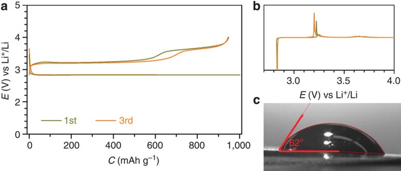
The carbon paper has been demonstrated to have negligible contribution to cell performance (Supplementary Fig. 1; Supplementary Note 1). The Li–O2 cell with Ru/MnO2/SP as cathode and the DMSO-based electrolyte containing p.p.m.-leveled H2O is discharged and charged at 500 mA g−1 (corresponding to 0.71 μA cm−2 based on the Brunauer-Emmett-Teller, (BET) surface area of Ru/MnO2/SP) as shown in Fig. 1a. A charge potential plateau as low as ∼3.20 V, corresponding to an overpotential of ∼0.24 V, can be clearly observed. Its corresponding dQ/dV curve in Fig. 1b shows sharp oxygen reduction reaction and oxygen evolution reaction peaks in the discharging and charging process, respectively, which are consistent with the flat discharge and charge plateaus. In addition, a small plateau at ∼3.60 V is also obtained in the charge profile in Fig. 1a. It could be resulted from the affinity of DMSO with the Ru/MnO2/SP cathode that has a large contact angle of 62°, compared with the discharge and charge profiles of the Li–O2 cell with a dimethoxyethane-(DME-)-based electrolyte and the good wettability of DME on the cathode in Supplementary Fig. 2. This may enable the oxygen evolved in a charging process to accumulate in the voids between the residual discharge product and the cathode, as schematically described in Supplementary Fig. 3 and Supplementary Note 2. It would induce slow diffusion of electrolytes into the voids for the decomposition of the remaining discharge products and result in the relatively large overpotential at ∼3.60 V, which is not observed in the affinitive DME-based electrolyte (Supplementary Fig. 2). Similar observations are also obtained in the other kinds of electrolytes, such as triglyme (G3)- and tetraglyme (G4)-based electrolytes (Supplementary Fig. 4). The trace amount of H2O in electrolytes is demonstrated to play a crucial role on reducing charge overpotentials of Li–O2 cells in all the widely used electrolytes, which was empirically considered as a negative factor in a Li-ion cell29.
Figure 1. Initial three cycles of discharge and charge.
(a) Discharge/charge profiles of the Li–O2 cells with a configuration of (Ru/MnO2/SP)/electrolyte/LiFePO4. The electrolyte is 0.5 M LiClO4 in DMSO with 120 p.p.m. H2O. (b,c) The corresponding dQ/dV curves and the contact angle of the electrolyte on the cathode. The discharge and charge cutoffs are 1,000 mAh g−1 (5,099 μC cm−2 based on the BET surface area of Ru/MnO2/SP) and 4.0 V, respectively. The potentials against Li+/Li are converted from LiFePO4. Rate: 500 mA g−1—based on the total weight of Ru, MnO2 and SP, corresponding to 0.71 μA cm−2; loading: ∼0.5 mg cm−2.
Analysis on the discharged/charged cathode
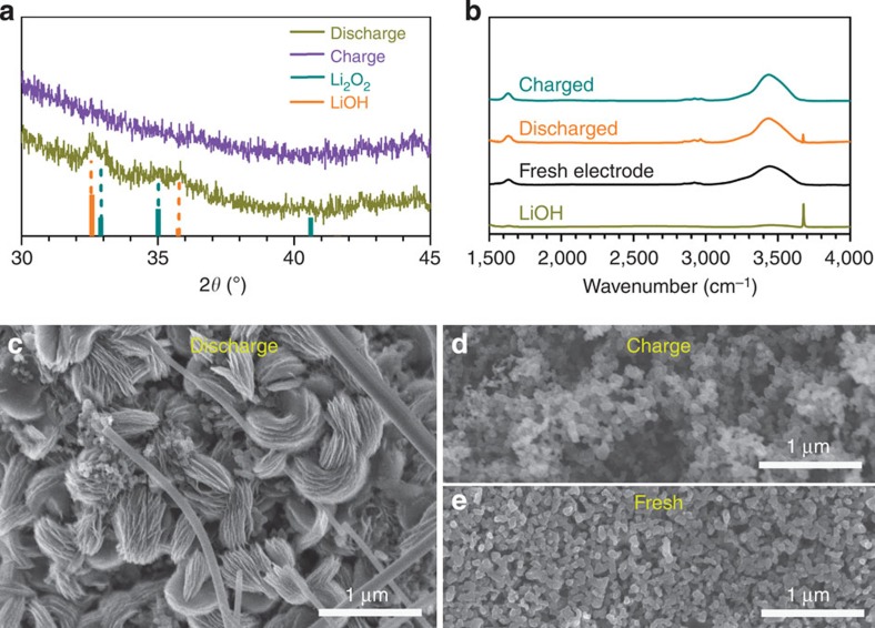
The discharged and charged Ru/MnO2/SP cathodes in the DMSO-based electrolyte containing water have been characterized by X-ray diffraction (XRD). As shown in Fig. 2a, the discharge products are identified as a mixture of LiOH and Li2O2, referring to the standard powder diffraction files of 01-085-0777 and 00-009-0355, respectively. The diffraction peaks of LiOH become sharper and stronger at the cathode with a discharge capacity of 4,000 mAh g−1 and addition of more electrolyte (Supplementary Fig. 5), suggesting more LiOH converted from Li2O2. To avoid the effect of MnO2, quantification of LiOH and Li2O2 was conducted on the Ru/SP cathode with the same discharge capacity as in Fig. 1 via iodometric titration. The discharge product Li2O2 reacts with H2O via Li2O2(s)+2H2O(l)→H2O2(l)+2LiOH(aq)30,31, where H2O2 further oxidizes iodide to iodine, the titrated target. The LiOH and Li2O2 in the discharged cathode were titrated via two steps (Supplementary Figs 6 and 7; titration processes in Supplementary Methods) and estimated to 16.02 and 1.48 μmol, respectively, which are in agreement with the XRD patterns of the discharged cathode in Fig. 2a. The majority of LiOH formed at a discharged cathode is revealed by the characteristic absorbance peak in the infrared (IR) spectra in Fig. 2b. Based on the electrons passing through the cathode and the oxygen derived from the discharge products of LiOH and Li2O2 by iodometric titration, the discharging process is a 1.97 e−/O2 process, quite close to the theoretical value of 2.00 e−/O2. It is confirmed that in other electrolytes, like DME-, G3- and G4-based electrolytes, the discharging process is also a ∼2.00 e−/O2 process, as listed in Supplementary Table 1. This suggests that LiOH is converted from Li2O2 via a chemical, not an electrochemical, process in the discharging processes.
Figure 2. Characterization of the discharged/charged cathodes.
(a) Ex situ XRD patterns of the discharged and charged Ru/MnO2/SP cathodes in DMSO-based electrolyte with 120 p.p.m. H2O. (b) IR spectra of the charged and discharge cathodes. (c,d) SEM images of the discharged and charged cathodes, in comparison to the fresh cathode (e).
After charge, the discharge products LiOH and Li2O2 were decomposed, as evidenced by the disappearance of their characteristic diffraction peaks in Fig. 2a. Further, the discharge products were directly observed by scanning electron microscope (SEM) in Fig. 2c. All the products are toroidal particles with obvious layering. These are quite similar to the toroidal aggregates in a Li2O2-only discharged cathode32,33, which may suggest that the LiOH was derived from Li2O2 in the presence of H2O in electrolytes by persisting the similar shape. The charged cathode becomes more porous after decomposition of the discharge products in Fig. 2d in comparison to the fresh cathode in Fig. 2e. These results indicate that the low charge overpotentials demonstrated in Fig. 1 and Supplementary Fig. 3 resulted from the electrochemical decomposition of LiOH.
Roles of Ru and MnO2 during discharge and charge
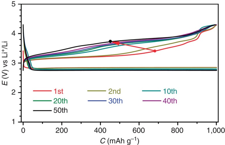
In the Ru/MnO2/SP cathode, all the components of Ru12,13, MnO2 (ref. 34) and SP35 nanoparticles can act as oxygen reduction reaction catalysts. However, in the charging processes either SP or MnO2 supported on SP (MnO2/SP) did not show any plateaus at ∼3.2 V but instead at >3.6 V (Supplementary Figs 8 and 9). Only the Ru/SP as revealed in Supplementary Fig. 10 presented low charge potentials. This suggests good catalytic activity of Ru nanoparticles on the decomposition of LiOH. Fig. 3 shows 50 cycles of discharge and charge of the Li–O2 cell with the Ru/SP cathode. The charge potentials are sustained at ∼3.20 V in the initial few cycles, and then quickly are increased to ∼3.65 V in the tenth cycle and beyond. It indicates that the majority of the discharge product Li2O2 after multiple cycles cannot be converted to LiOH, because the p.p.m.-leveled H2O in the electrolyte was gradually consumed in the charging processes to produce H2O2. Hence, MnO2 (EMD), the best disproportionation catalyst of H2O2 (ref. 36), was incorporated into Ru/SP to regenerate H2O via 2H2O2(l)→2H2O(l)+O2(g) and make H2O circulate during cycles and improve cycling stability of the Li–O2 cell.
Figure 3. Discharge/charge profiles of the Li–O2 cell with Ru/SP.
The charge potentials are steeply increased with cycles. Rate: 250 mA g−1.
Rate capability and cycling stability
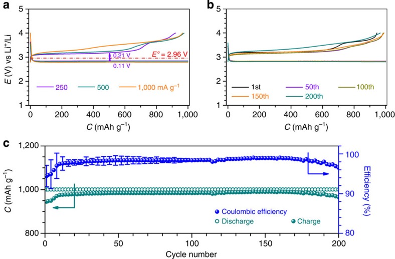
The Li–O2 cell with Ru/MnO2/SP and the DMSO-based electrolyte containing p.p.m.-leveled H2O was examined at varied current densities, as shown in Fig. 4a. The polarization is obviously increased with the current density from 250 to 500 and 1,000 mA g−1. The overpotential in the discharging and charging process at 250 mA g−1 is 0.11 V and 0.21 V, respectively, leading to a small discharge/charge potential gap of 0.32 V. The Li–O2 cell was continuously discharged and charged at 500 mA g−1 for 200 cycles and ∼800 h, and the selected runs of discharge and charge are shown in Fig. 4b. The discharge and charge curves during the first 150 cycles are almost overlapped except the first charge. A slight charge potential increase beyond the 150 cycles can also be observed, which could be related to the electrolyte instability during many cycles (Supplementary Fig. 11)37,38. This indicates superior cycling stability of the Li–O2 cell, which is in sharp contrast to that without MnO2 in Fig. 3. The discharge and charge capacities in the 200 cycles are almost constant, and the corresponding coulombic efficiency in each run is approaching 98% (Fig. 4c), indicative of good reversibility. This may be partially benefited from the conversion of chemically active Li2O2 to LiOH. The reversible formation and decomposition of LiOH and Li2O2 during the 200 cycles are further confirmed by ex situ XRD patterns in Supplementary Fig. 12 and SEM images in Supplementary Fig. 13 (Supplementary Note 3). The low charge potentials sustained for so many cycles, to the best of our knowledge, have never been achieved before. The small discharge/charge potential gap and good cycling stability of the Li–O2 cell are rewarded by the ‘water catalysis' at the Ru/MnO2/SP cathode.
Figure 4. Rate capability and cycling performance of the Li–O2 cells with Ru/MnO2/SP.
(a) Discharge/charge profiles of the tenth run at varied current densities from 250 to 500 and 1,000 mA g−1. (b) Discharge/charge profiles of the selected runs over the 200 cycles at 500 mA g−1. The cell was at rest for 1 min between each run. (c) Plot of discharge/charge capacities and the corresponding coulombic efficiencies against cycle number and error bars (s.e.m.) in the first 100 cycles.
Reaction mechanism
The equilibrium potential of LiOH in an aqueous solution is estimated to be ∼3.42 V vs Li+/Li based on Nernst equation34,39. However, in this studied electrolyte system the trace amount of H2O and LiClO4 are both the solutes and DMSO is the solvent. The equilibrium potential of LiOH is dependent on the concentration of H2O, and it can be roughly estimated to be ∼3.20 V, considering a concentration of 100 p.p.m. of H2O in the electrolyte (see the estimation process in Supplementary Methods). This is in good agreement with the observed low charge potential plateaus in all the widely employed electrolytes DMSO-, DME-, G3- and G4-based electrolytes for Li–O2 cells in Figs 1 and 4 and Supplementary Fig. 3.
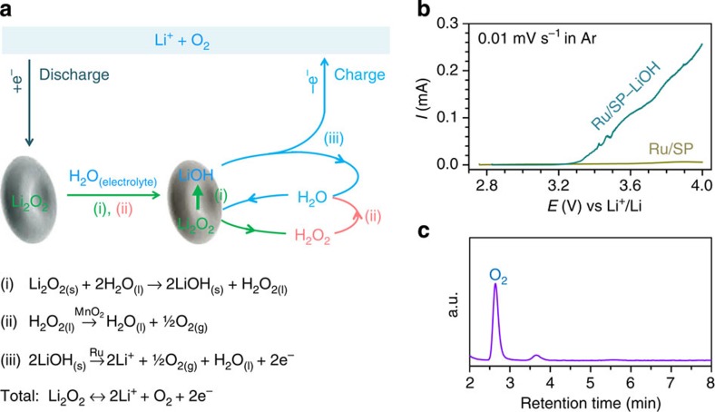
Based on the above results, a mechanism for the discharging and charging process of the cell with Ru/MnO2/SP and the electrolyte containing a trace amount of H2O can be proposed and schematically described in Fig. 5a. On discharging, O2 accepts electrons via the external circuit and is reduced to generate the primary discharge product Li2O2 (refs 40, 41, 42). At the same time, the Li2O2 reacts with H2O from the electrolyte and is converted to LiOH via Steps (i and ii). Although Step (i) is an equilibrium26, it can be largely promoted to move forward by the conversion of one of the products H2O2 to H2O over MnO2 via Step (ii)36. The two Steps (i and ii) occur sequentially, and quickly transform Li2O2 to LiOH as long as H2O remains in the electrolyte. This has been confirmed by the presence of substantial LiOH in discharged cathodes as revealed by both of the XRD patterns and the IR spectra in Fig. 2. This is consistent with the observations of Aetukuri et al.25, and Schwenke et al.26, where the H2O in electrolytes is possibly consumed by the employed Li anode or saturated by the product LiOH, and the lack of a promoter like MnO2 for Step (ii) made the equilibrium reaction in Step (i) to move backward and result in the major discharge product Li2O2 as detected.
Figure 5. Proposed reaction mechanism, LSV and gas analysis.
(a) (i) is a spontaneous process; (ii) is promoted over MnO2 nanoparticles in Ru/MnO2/SP; and oxidation of LiOH in (iii) occurs at low charge overpotentials over Ru nanoparticles. (b) Linear scanning voltammetry (LSV) curves of the Ru/SP electrodes with and without LiOH under Ar atmosphere. (c) Gas chromatography (GC) analysis on the gas evolved in a charging process.
In the following charging process, the resultant LiOH can be directly oxidized via Step (iii) to regenerate H2O at low charge potentials, by which the residual Li2O2 is then converted to LiOH via Steps (i and ii) and oxidized. To demonstrate the feasibility of Step (iii), commercial LiOH was ball-milled and then thoroughly mixed with Ru/SP with a ratio of 30:70 (wt/wt). The electrodes of Ru/SP with and without LiOH under Ar atmosphere were subjected to linear scanning voltammetry (LSV) at a low scan rate of 0.01 mV s−1 as depicted in Fig. 5b. The Ru/SP electrode incorporated with LiOH presents significant oxidation currents and an oxidation onset potential of ∼3.27 V in Fig. 5b, which is in sharp contrast with no oxidation response on the electrode without LiOH. At a carbon electrode pre-filled with LiOH, a high charge potential of >4.0 V was reported43. This suggests that over Ru/SP LiOH was oxidized at low potentials, though it may be dependent on its morphology and facet orientation and the catalyst. The gas evolved in a charging process can be identified as O2 by a gas chromatography (GC) mounted with a thermal conductivity detector, as evidenced by the sharp GC signal of O2 in Fig. 5c. As shown in the whole discharging and charging process in Fig. 5a, H2O is not consumed and can be circulated to behave like a catalyst. The total electrochemical reaction occurring at the oxygen cathode is 2Li++O2+2e−↔Li2O2, consistent with the Li–O2 cell chemistry.
Discussion
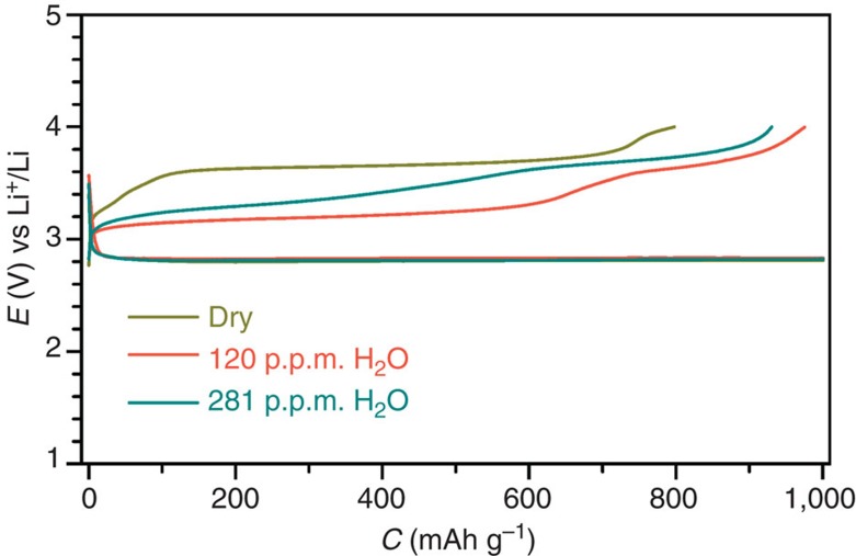
The dependence of the charge potentials on the concentration of H2O in electrolytes is shown in Fig. 6. In the dried DMSO-based electrolyte, one charge potential plateau can be obtained at ∼3.65 V, which is attributed to the oxidation of Li2O2 and in good agreement with the literatrues10,11,12,13,14,15. When there is 120 p.p.m. of water in the electrolyte, the charge potential plateau is significantly reduced to ∼3.2 V. This has been confirmed to the oxidation of LiOH that can be quickly converted from the primary discharge product Li2O2 via the sequential Steps (i and ii) in Fig. 5a over the catalyst of Ru/MnO2/SP in both the discharging and charging processes. However, when the concentration of water in the electrolyte is increased to 281 p.p.m., the charge potential plateau is shortened and increased. It may be induced by the LiOH on the surface of the discharge product, which is surrounded/adsorbed by H2O molecules in the electrolyte, and hence has high oxidation potentials following the Nernst equation17,32,33.
Figure 6. Discharge/charge profiles of the fifth cycles of the Li–O2 cells with Ru/MnO2/SP.
The applied DMSO-based electrolytes are dried over a Li foil, and contain 120 and 281 p.p.m. of H2O. Rate: 500 mA g−1.
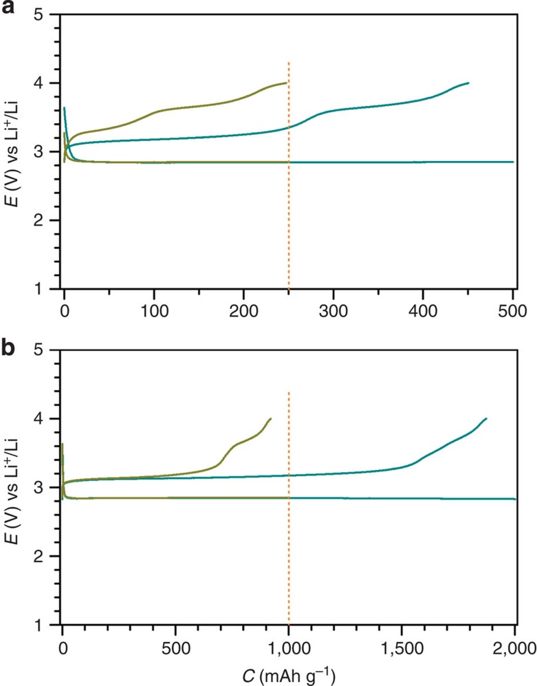
In addition, by controlling the discharge depth of the Li–O2 cells, the discharge product can be ranged from LiOH only to a majority of Li2O2 plus LiOH with the same amount of electrolytes used in cells. The cathode with a relatively small discharge capacity of 250 mAh g−1 was covered with LiOH, on which no Li2O2 was detected by iodometric titration. It is in the shape of thin disks as shown in Supplementary Fig. 14 (refs 25, 33). In the following charging process, the potentials are increased to ∼3.65 V and similar to that with 281 p.p.m. of H2O in electrolytes in Fig. 6. The low charge potentials at ∼3.20 V can be observed again when the discharge capacity is increased to 500, 1,000 and 2,000 mAh g−1, as shown in Fig. 7. At large discharge capacities, the H2O molecules in the electrolyte can be consumed by Li2O2, producing surface-clean LiOH/Li2O2 in the cathode. This suggests that the relative amounts of H2O, LiOH and Li2O2 coexisting at a cathode side affect the charging overpotentials. The detailed formation/decomposition mechanism of LiOH and Li2O2 in the presence of water in electrolytes and the dependence of their decomposition potentials on their morphologies deserve further investigation.
Figure 7. Discharge/charge profiles of the fifth cycles of the Li–O2 cell at 250 mA g−1.
(a) Discharge capacity is limited for 250 and 500 mAh g−1. (b) Discharge capacity is limited for 1,000 and 2,000 mAh g−1. The cathode is Ru/MnO2/SP and the DMSO-based electrolyte containing 120 p.p.m. of H2O is applied.
The ‘water catalysis' at the oxygen cathode side has been demonstrated to reduce the charge overpotentials to ∼0.24 V, corresponding to ∼3.20 V vs Li+/Li and provides a possible solution to the current challenges of Li–O2 cells. With the Ru/MnO2/SP cathode and the DMSO-based electrolyte containing p.p.m.-leveled H2O, the Li–O2 cell presents a small discharge/charge potential gap of 0.32 V and superior cycling stability of 200 cycles ∼800 h. These have not been achieved before, and are rewarded by the proposed reaction mechanism. Although the LiFePO4 applied in cells is not a practical anode of Li–O2 cells, the reaction mechanism at the oxygen cathode may be extended to a practical Li–O2 cell by using a Li+ ion-conducting ceramic membrane to separate the electrolyte with water and the Li anode2,39. This could also alleviate the carbon-related side reactions by converting the chemically active Li2O2 to LiOH, and it will make the cheap and lightweight carbon possible as cathodes in Li–O2 cells, which has been suggested to avoid. This investigation will enable the cell to operate in ambient air by eliminating CO2 and advance the Li–O2/air cell technology.
Methods
Materials preparation
Electrolytic MnO2 (EMD, γ-MnO2) was received from TOSOH, Japan and ball-milled to nanometre scale. Ru/SP was synthesized as follows: 85 mg of SP was stirred into a solution of ethylene glycol (EG, purity of >99.5%, Wako Chemicals) containing 7.5 mg of Ru in RuCl3·xH2O (purity of 36∼42 wt% based on Ru, Wako Chemicals), and its pH was adjusted to 13 with 0.1 M of NaOH in EG. The suspension was then heated to 160 °C for 3 h with flowing N2. After cooling to 80 °C, its pH was adjusted to 3 using 0.1 M HCl and the resulting mixture was further stirred for 12 h. The final product Ru/SP was centrifuged, washed with de-ionized water until the solution pH reached ∼7 and dried at 80 °C in a vacuum oven for 12 h. For the preparation of MnO2/Ru/SP, the as-synthesized Ru/SP and MnO2 nanoparticles with a weight ratio Ru/MnO2/SP=7.5:7.5:85 were sonicated into an ethanol aqueous solution for 3 h and stirred overnight. Then, the product MnO2/Ru/SP was collected and dried at 80 °C under vacuum for 12 h.
DMSO, DME, G3 and G4 were firstly dried over 4 Å molecular sieves and then using Li metal. The Li salts of LiClO4 and lithium bis(fluorosulfonyl)imide were used as received from Wako Chemicals. The water in the prepared electrolytes was from the Li salts and measured on a desk-top Karl–Fisher Titration instrument.
Cell assembly
The electrode film composed of Ru/MnO2/SP or Ru/SP and PTFE (A dispersion of 60 wt%, Du Pont-Mitsui Fluorochemicals Co. Ltd.) with a ratio of 85:15 wt% was rolled with a glass rod. The mass loading of Ru/MnO2/SP or Ru/SP is ∼0.5 mg cm−2. The electrode film was pressed onto a hydrophobic carbon paper (SIGRACET Gas Diffusion Media, Type GDL 35BA) to work as a cathode. The anode was consisted of LiFePO4 (Sumitomo Osaka Cement), SP and PTFE (70/20/10) pressed on an Al mesh. The amount of DMSO- and DME-based electrolytes in a coin cell was 100 μl and G3- and G4-based electrolyte was 50 μl, considering their different vapour pressures. The employed separator was a glass microfibre filter paper (GF/A, Whatman). The Li–O2 cell assembly in 2032 coin cells was conducted in an Ar-filled glove box that has a dew point of around −90 °C (∼0.1 p.p.m. of H2O) and O2 content below 5 p.p.m.. The cells stored in a glass chamber with a volume capacity of 650 ml were purged with O2 (99.999%) before electrochemical tests.
Characterization and measurements
The contact angles of electrolytes on the cathode were examined on AST Products with a model of Optima. The BET surface area of Ru/MnO2/SP was measured to be 70.6 m2 g−1 on Belsorp 18 via nitrogen adsorption–desorption. XRD was performed on a Bruker D8 Advanced diffractometer with Cu Kα (λ=1.5406 Å) radiation with a scan rate of 0.016° per s. Galvanostatic discharge/charge was conducted on a Hokuto discharging/charging system. All the electrochemical measurements were conducted at 25 °C. The specific capacities and currents are based on the mass of Ru/MnO2/SP or Ru/SP in cathodes. The discharged and charged cathodes were extracted in the glove box and washed with dried dimethoxyethane. SEM was obtained on Hitachi S4800. The Ru/MnO2/SP was mixed with KBr and then pressed to a pellet for Fourier transform infrared spectroscope (FTIR) characterization on a JASCO instrument of FT/IR-6,200 from 2,000 to 400 cm−1 with a resolution of 2 cm−1. The electrolytes during cycles were collected by washing the glass fibre filter separators with acetone-d6, and subjected to 1H NMR (Bruker, 500 MHz).
Additional information
How to cite this article: Li, F. et al. The water catalysis at oxygen cathodes of lithium–oxygen cells. Nat. Commun. 6:7843 doi: 10.1038/ncomms8843 (2015).
Supplementary Material
Supplementary Figures 1-14, Supplementary Table 1, Supplementary Notes 1-3 and Supplementary Methods
Acknowledgments
The financial supports from Mitsubishi Motors Corporation, the National Basic Research Program of China (2014CB932302) and ALCA project are acknowledged.
Footnotes
Author contributions F.L. designed and performed the experiments; S.W. examined water contents in electrolytes and their contact angles; all the authors contributed to the discussion of the manuscript; F.L, H.Z., and A.Y. wrote the manuscript; H.Z. supervised the work
References
- Abraham K. M. & Jiang Z. A polymer electrolyte-based rechargeable lithium/oxygen battery. J. Electrochem. Soc. 143, 1–5 (1996). [Google Scholar]
- Girishkumar G., McCloskey B., Luntz A. C., Swanson S. & Wilcke W. Lithium-air battery: promise and challenges. J. Phys. Chem. Lett. 1, 2193–2203 (2010). [Google Scholar]
- Bruce P. G., Freunberger S. A., Hardwick L. J. & Tarascon J.-M. Li-O2 and Li-S batteries with high energy storage. Nat. Mater. 11, 19–29 (2012). [DOI] [PubMed] [Google Scholar]
- Thotiyl M. M. O., Freunberger S. A., Peng Z. & Bruce P. G. The carbon electrode in nonaqueous Li-O2 cells. J. Am. Chem. Soc. 135, 494–500 (2013). [DOI] [PubMed] [Google Scholar]
- Gallant B. M. et al. Chemical and morphological changes of Li-O2 battery electrodes upon cycling. J. Phys. Chem. C 116, 20800–20805 (2012). [Google Scholar]
- Mizuno F., Nakanishi S., Kotani Y., Yokoishi S. & Iba H. Rechargeable Li-air batteries with carbonate-based liquid electrolytes. Electrochemistry 78, 403–405 (2010). [Google Scholar]
- Freunberger S. A. et al. Reactions in the rechargeable lithium-O2 battery with alkyl carbonate electrolytes. J. Am. Chem. Soc. 133, 8040–8047 (2011). [DOI] [PubMed] [Google Scholar]
- Xiao J. et al. Investigation of the rechargeability of Li-O2 batteries in non-aqueous electrolyte. J. Power Sources 196, 5674–5678 (2011). [Google Scholar]
- McCloskey B. D. et al. Twin problems of interfacial carbonate formation in non-aqueous Li-O2 batteries. J. Phys. Chem. Lett. 3, 997–1001 (2012). [DOI] [PubMed] [Google Scholar]
- Peng Z., Freunberger S., Chen Y. & Bruce P. G. A reversible and higher-rate Li-O2 battery. Science 337, 563–566 (2012). [DOI] [PubMed] [Google Scholar]
- Thotiyl M. M. O. et al. A stable cathode for the aprotic Li-O2 battery. Nat. Mater. 12, 1050–1056 (2013). [DOI] [PubMed] [Google Scholar]
- Li F. et al. Ru/ITO: a carbon-free cathode for nonaqueous Li-O2 battery. Nano Lett. 13, 4702–4707 (2013). [DOI] [PubMed] [Google Scholar]
- Li F. et al. Li-O2 battery based on highly efficient Sb-doped tin oxide supported Ru nanoparticles. Adv. Mater. 26, 4659–4664 (2014). [DOI] [PubMed] [Google Scholar]
- Li F. et al. Superior performance of a Li-O2 battery with metallic RuO2 hollow spheres as the carbon-free cathode. Adv. Energy Mater. doi: 10.1002/aenm.201500294 (2015). [DOI] [Google Scholar]
- Lu J. et al. Aprotic and aqueous Li-O2 batteries. Chem. Rev. 114, 5611–5640 (2014). [DOI] [PubMed] [Google Scholar]
- Li F., Zhang T. & Zhou H. Challenges of non-aqueous Li-O2 batteries: electrolytes, catalysts, and anodes. Energy Environ. Sci. 6, 1125–1141 (2013). [Google Scholar]
- Shao Y. et al. Making Li-air batteries rechargeable: material challenges. Adv. Funct. Mater. 23, 987–1004 (2013). [Google Scholar]
- Lu Y.-C. & Shao-Horn Y. Probing the reaction kinetics of the charge reactions of nonaqueous Li-O2 batteries. J. Phys. Chem. Lett. 4, 93–99 (2013). [DOI] [PubMed] [Google Scholar]
- Kang S. Y., Mo Y., Ong S. P. & Ceder G. A facile mechanism for recharging Li2O2 in Li-O2 batteries. Chem. Mater. 25, 3328–3336 (2013). [Google Scholar]
- Chen Y., Freunberger S. A., Peng Z., Fontaine O. & Bruce P. G. Charging a Li-O2 battery using a redox mediator. Nat. Chem. 5, 489–494 (2013). [DOI] [PubMed] [Google Scholar]
- Lim H. D. et al. Superior rechargeability and efficiency of lithium–oxygen batteries: hierarchical air electrode architecture combined with a soluble catalyst. Angew. Chem. Int. Ed. 53, 3926–3931 (2014). [DOI] [PubMed] [Google Scholar]
- Meini S., Solchenbach S., Piana M. & Gasteiger H. A. The role of electrolyte solvent stability and electrolyte impurities in the electrooxidation of Li2O2 in Li-O2 batteries. J. Electrochem. Soc. 161, A1306–A1314 (2014). [Google Scholar]
- Wang Y. & Xia Y. Li-O2 batteries: an agent for change. Nat. Chem. 5, 445–447 (2013). [DOI] [PubMed] [Google Scholar]
- Meini S., Piana M., Tsiouvaras N., Garsuch A. & Gasteiger H. A. The effect of water on the discharge capacity of a non-catalysed carbon cathode for Li-O2 batteries. Electrochem. Solid State Lett. 15, A45–A48 (2012). [Google Scholar]
- Aetukuri N. B. et al. Solvating additives drive solution-mediated electrochemistry and enhance toroid growth in non-aqueous Li-O2 batteries. Nat. Chem. 7, 50–56 (2015). [DOI] [PubMed] [Google Scholar]
- Schwenke K. U., Metzger M., Restle T., Piana M. & Gasteiger H. A. The influence of water and protons on Li2O2 crystal growth in aprotic Li-O2 cells. J. Electrochem. Soc. 162, A573–A585 (2015). [Google Scholar]
- Guo Z., Dong X., Yuan S., Wang Y. & Xia Y. Humidity effect on electrochemical performance of Li-O2 batteries. J. Power Sources 264, 1–7 (2014). [Google Scholar]
- Cho M. H. et al. The effects of moisture contamination in the Li-O2 battery. J. Power Sources 268, 565–574 (2014). [Google Scholar]
- Aravindan V., Gnanaraj J., Madhavi S. & Liu H. K. Lithium-ion conducting electrolyte salts for lithium batteries. Chem. Eur. J. 17, 14326–14346 (2011). [DOI] [PubMed] [Google Scholar]
- Black R. et al. Screening for superoxide reactivity in Li-O2 batteries: effect on Li2O2/LiOH crystallization. J. Am. Chem. Soc. 134, 2902–2905 (2012). [DOI] [PubMed] [Google Scholar]
- McCloskey B. D. et al. Combining accurate O2 and Li2O2 assays to separate discharge and charge stability limitations in nonaqueous Li-O2 batteries. J. Phys. Chem. Lett. 4, 2989–2993 (2013). [DOI] [PubMed] [Google Scholar]
- Oh S. H., Black R., Pomerantseva E., Lee J.-H. & Nazar L. F. Synthesis of a metallic mesoporous pyrochlore as a catalyst for lithium-O2 batteries. Nat. Chem. 4, 1004–1010 (2012). [DOI] [PubMed] [Google Scholar]
- Mitchell R. R., Gallant B. M., Shao-Horn Y. & Thompson C. V. Mechanisms of morphological evolution of Li2O2 particles during electrochemical growth. J. Phys. Chem. Lett. 4, 1060–1064 (2013). [DOI] [PubMed] [Google Scholar]
- Cheng F. & Chen J. Metal-air batteries: from oxygen reduction electrochemistry to cathode catalysts. Chem. Soc. Rev. 41, 2172–2192 (2012). [DOI] [PubMed] [Google Scholar]
- Jung H.-G., Hassoun J., Park J.-B., Sun Y.-K. & Scrosati B. An improved high-performance lithium–air battery. Nat. Chem. 4, 579–585 (2012). [DOI] [PubMed] [Google Scholar]
- Giordani V., Freunberger S. A., Bruce P. G., Tarascon J.-M. & Larcher D. H2O2 decomposition reaction as selecting tool for catalysts in Li-O2 cells. Electrochem. Solid State Lett. 13, A180–A183 (2010). [Google Scholar]
- Trahan M. J., Mukerjee S., Plichta E., Hendrickson M. A. & Abraham K. M. Studies of Li-air cells utilizing dimethyl sulfoxide-based electrolyte. J. Electrochem. Soc. 160, A259–A267 (2013). [Google Scholar]
- Sharon D. et al. Oxidation of dimethyl sulfoxide solutions by electrochemical reduction of oxygen. J. Phys. Chem. Lett. 4, 3115–3119 (2013). [Google Scholar]
- Manthiram A. & Li L. Hybrid and aqueous lithium-air batteries. Adv. Energy Mater. 5, 1–17 (2015).26190957 [Google Scholar]
- Laoire C. O., Mukerjee S. & Abraham K. M. Elucidating the mechanism of oxygen reduction for lithium-air battery applications. J. Phys. Chem. C 113, 20127–20134 (2009). [Google Scholar]
- McCloskey B. D., Scheffler R., Speidel A., Girishkumar G. & Luntz A. C. On the mechanism of nonaqueous Li-O2 electrochemistry on carbon and its kinetic overpotentials: some implications for Li-air batteries. J. Phys. Chem. C 116, 23897–23905 (2012). [Google Scholar]
- Johnson L. et al. The role of LiO2 solubility in O2 reduction in aprotic solvents and its consequences for Li-O2 batteries. Nat. Chem. 6, 1091–1099 (2014). [DOI] [PubMed] [Google Scholar]
- Meini S. et al. Rechargeability of Li-air cathodes pre-filled with discharge products using an ethe-based electrolyte solution: implications for cycle-life of Li-air cells. Phys. Chem. Chem. Phys. 15, 11478–11493 (2013). [DOI] [PubMed] [Google Scholar]
Associated Data
This section collects any data citations, data availability statements, or supplementary materials included in this article.
Supplementary Materials
Supplementary Figures 1-14, Supplementary Table 1, Supplementary Notes 1-3 and Supplementary Methods


