Abstract
Enrichment of rare cell populations such as Circulating Tumor Cells (CTCs) is a critical step before performing analysis. This paper presents a polymeric microfluidic device with integrated thick Carbon-PolyDimethylSiloxane composite (C-PDMS) electrodes designed to carry out dielectrophoretic (DEP) trapping of low abundance biological cells. Such conductive composite material presents advantages over metallic structures. Indeed, as it combines properties of both the matrix and doping particles, C-PDMS allows the easy and fast integration of conductive microstructures using a soft-lithography approach while preserving O2 plasma bonding properties of PDMS substrate and avoiding a cumbersome alignment procedure. Here, we first performed numerical simulations to demonstrate the advantage of such thick C-PDMS electrodes over a coplanar electrode configuration. It is well established that dielectrophoretic force () decreases quickly as the distance from the electrode surface increases resulting in coplanar configuration to a low trapping efficiency at high flow rate. Here, we showed quantitatively that by using electrodes as thick as a microchannel height, it is possible to extend the DEP force influence in the whole volume of the channel compared to coplanar electrode configuration and maintaining high trapping efficiency while increasing the throughput. This model was then used to numerically optimize a thick C-PDMS electrode configuration in terms of trapping efficiency. Then, optimized microfluidic configurations were fabricated and tested at various flow rates for the trapping of MDA-MB-231 breast cancer cell line. We reached trapping efficiencies of 97% at 20 μl/h and 78.7% at 80 μl/h, for 100 μm thick electrodes. Finally, we applied our device to the separation and localized trapping of CTCs (MDA-MB-231) from a red blood cells sample (concentration ratio of 1:10).
I. INTRODUCTION
Trapping and concentration of cells have numerous applications in medicine and biotechnology. In particular, numerous studies have been recently published concerning the trapping of low-abundance cells in microfluidics.1,2 Dharmasiri et al.1 defined a sample of low-abundance cells, as a sample where the target cell concentration is less than 1000 target cells/ml. Typical examples of low-abundance cells are enumerated by the authors as circulating tumor cells (CTCs), circulating fetal cells, stem cells, HIV (Human Immunodeficiency Virus) infected T cells and red blood cells (RBC) infected by parasites (e.g., Plasmodium falciparum), some bacteria, or viruses. Different approaches for rare cell sorting have already been integrated in microfluidic systems.1–5 They can mainly be divided in two groups: affinity-based and label-free approaches. In the first case, immunological recognition between antibodies and antigens is used, whereas in the latter, capture is obtained due to physical property modification. For both approaches, the use of a field gradient, electrical field for dielectrophoretic (DEP), and magnetic field for immuno-magnetic separations has gained a large interest. However, to be applied to real clinical samples and become commercial products, these devices and methodologies still need development. DEP is defined as the movement of a polarizable particle in a non-uniform electric field.6 In the case of biological cells, the DEP force applied on the cell is function of its polarizability, which depends on its membrane and cytoplasmic electrical properties, as well as its size, on the electrical properties of the medium and on the applied electric field (amplitude, gradient and frequency). The cell response to the electric field is very specific and can allow differentiation of cells even with similar shape or size without requiring biochemical or magnetic labeling.2
However, trapping of low abundance cell population using DEP technique remains challenging, particularly in terms of trapping efficiency2 and throughput. Indeed, as the target cell concentration decreases, it becomes more crucial to achieve almost 100% capture to collect sufficient amount of cells for subsequent analysis or treatment. To do so, the DEP force has to overcome other forces acting on cells in the device in order to (i) deviate cells towards the traps whatever their position in the channel and (ii) maintain cells trapped in order to achieve pre-concentration. In the channel, the dielectrophoretic force is mainly in competition with the drag force, , and thus, dielectrophoretic trapping is generally performed at low flow rate.7 Most of the devices dedicated to DEP trapping are realized by integrating coplanar microfabricated electrodes, with geometries consisting generally of interdigitated8 or castellated9 electrode arrays. However, decreases quickly as the distance from the electrode surface increases. Therefore, according on their position in the channel depth, cells do not experience the same DEP force in such coplanar configuration. In the case of electrodes as thick as the microchannel height, the electric field gradient, and thus the associated DEP force, is generated over the whole height of the microsystem. The DEP force extends its influence in the whole volume of the channel compared to coplanar electrode configuration.6,10–14
However, thick electrodes are technologically more challenging to produce and integrate in microfluidic channels than thin coplanar electrodes. In literature, thick electrodes are mainly made of metals, doped silicon, and carbon. In the case of metallic structures such as Cu and Au, thick electrodes are generally obtained by UV-LIGA approach, where electrodeposition is carried out after photolithography.11,15,16 Their integration in polydimethylsiloxane (PDMS) microfluidic devices can be complex, time-consuming and necessitates cumbersome alignment procedure. In addition, metals cannot be efficiently sealed to PDMS using simple O2 plasma treatment which can result in tightness issue. The second material, doped silicon, presents the advantage of easy bonding to PDMS—thanks to O2 plasma surface activation.12,17,18 However, the fabrication process is time-consuming and requires relatively expensive equipment such as Deep Reactive Ion Etching which is not compatible with rapid prototyping. Finally, carbon electrodes are particularly advantageous for DEP application as they present the advantage to be biocompatible and chemically inert with almost all solvents. In addition, carbon has a much wider electrochemical window than metals, and thus limits electrolysis issues at low frequency. Thick carbon electrodes13,14 can be obtained and integrated in microfluidic structures using mainly two approaches: photoresist carbonization and preparation of a composite PDMS with carbon nanoparticles (C-PDMS). Photoresist carbonization requires expensive substrates and presents also sealing issues as carbon does not stick with PDMS. Other approaches such as insulator based DEP has been reported in literature.19,20 In particular, contactless DEPs enable to eliminate any contact between the electrode and the medium.7,21 However, the fabrication of a robust membrane presenting appropriate thickness between the main channel and the side channel containing conductive fluid remains challenging. The use of C-PDMS is an elegant technological answer to heterogeneous integration in PDMS devices. Indeed, C-PDMS preserves PDMS properties such as compatibility with soft-lithography process and plasma bonding, while being conductive.22,23 We demonstrated in previous works the capacity of C-PDMS electrodes embedded in PDMS microchannel to carry out DEP and electrical lysis in stagnant mode. However, these results were obtained using parallel plane electrodes where gradient of electrical field was induced by electrode roughness and therefore were not adapted for rare cell capture.
The objective here was to design thick carbon electrodes using a PDMS composite approach and demonstrate the advantage of such configuration for cell capture in flow conditions. We first carried out a numerical comparison between coplanar and thick electrode configurations. Then, we designed various thick electrode geometries and tested them for breast cancer cell (MDA-MB-231) capture. Finally, we illustrated the performance of this configuration by employing these electrodes for the capture of CTCs in RBC sample.
II. MATERIAL AND METHODS
A. Cell preparation
MDA-MB-231, HBL100, and MCF7 are immortalized cell lines of human breast cancer. Cells were grown in Dulbecco's Modified Eagle's Medium (DMEM) supplemented with 10% fetal bovine serum (FBS), and 1% penicillin–streptomycin (PS) in a 5% CO2 and 95% O2 atmosphere at 37 °C.
For operation in the DEP device, cells were first re-suspended with Trypsin and then washed by centrifugation in DMEM. Finally, cells were then suspended in a widely used low conductivity DEP buffer5,7,24–26 composed of 8.5% (w/v) sucrose, 0.3% (w/v) glucose and 0.7% (v/v) DMEM. Conductivity and pH of this DEP buffer were, respectively, measured to be 10−2 S/m and pH ∼ 7. Cell concentrations were typically between 4 and 8 × 10⁶ cells/ml.
MDA-MB-231 cells were also used as model for CTC capture experiment. To prepare model CTC solution, peripheral blood samples were collected by Etablissement Français du Sang (EFS) from healthy donor. Then, RBC were separated from white blood cells and platelets by centrifugation, washed in Phosphate-Buffered Saline (PBS), and then diluted with DEP buffer at a typical concentration of 50 × 106 RBC/ml−1. MDA-MB-231 and RBC were finally mixed at a ratio of 1:10.
B. Electrode design and fabrication
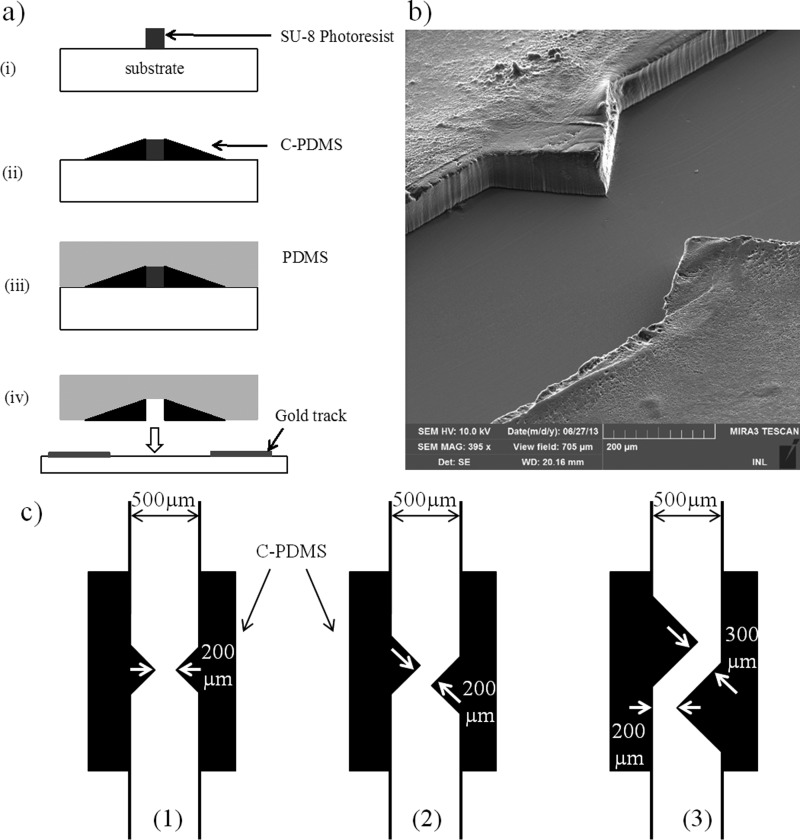
Microfluidic devices incorporating C-PDMS thick electrodes were prepared according to previously described protocol22 (Fig. 1(a)). Briefly, C-PDMS was obtained by incorporating carbon black nanoparticles (Vulcan XC72-R, Cabot, Inc.) into PDMS (Sylgard 184, Dow Corning) at a concentration of 25% w/w. PDMS and carbon nanoparticles were mixed for 15 min by hand, until obtaining a homogeneous paste. C-PDMS was then plastered on a mold obtained by photolithography, and the excess of conductive polymer was removed with a blade. Depending on the photoresist thickness, we investigated C-PDMS electrodes that were 50 and 100 μm thick. After curing (75 °C, 30 min), pure PDMS was poured on this mold and was cured again at 75 °C for 2 h. The C-PDMS/PDMS channel was then unmolded and bounded by oxygen plasma (P(O2) = 900 mTorr, 30 s) to a glass substrate that was patterned with evaporated Au tracks. These tracks were used to ensure electrical contact with C-PDMS electrodes and to supply pads for wire soldering. The quality of the plasma bonding between C-PDMS and glass was comparable to that of PDMS and glass, thus avoiding leaks at the electrodes and ensuring a tight device as demonstrated in previous works.22,27
FIG. 1.
(a) Fabrication process: (i) photolithography, (ii) C-PDMS deposition, (iii) PDMS pouring, and (iv) demolding and plasma bounding on glass substrate. (b) SEM picture of C-PDMS electrodes before sealing; visible asperities on the surface of C-PDMS electrodes can be explained by the paste-like behavior of C-PDMS during molding. (c) Illustration of the three configurations of electrodes realized: (1) face-to-face, (2) slightly shifted, and (3) shifted.
We fabricated three different configurations of C-PDMS thick electrodes integrated in the walls of PDMS channels (Fig. 1(b)). The electrodes were triangular electrodes positioned face to face (Fig. 1(c-1)), slightly shifted (Fig. 1(c-2)), or shifted (Fig. 1(c-3)). At a concentration of 25% w/w, C-PDMS has a conductivity of 10 S m−1 and is a viscous paste-like material, not easily patternable in acute angles. So, we chose to design electrodes with the shape of isosceles right-angled triangles. As the channel cross section impacts the drag force, the minimal width of the channel was chosen at 200 μm for the three configurations in order to facilitate comparison.
C. Experimental set-up
Microsystems were placed on an inverted epifluorescence microscope (LEICA DMI4000B), and a camera (LEICA DFC340 FX) was used for data acquisition. Image J® was used to perform image analysis and to retrieve cell trajectories. Before operation, microsystems were passivated with 2% bovine Serum Albumin (BSA) in PBS in order to avoid any non-specific adsorption and then rinsed with PBS. A syringe pump (Harvard Apparatus) was used to inject the solutions. Electrical fields were supplied through a waveform generator (Agilent 33521 A) and a High Voltage Amplifier (FLC Electronics Voltage Amplifier A800) connected to the microsystems. In this work, the voltage used for DEP experiments is expressed as peak-to-peak voltage. Experiments were conducted at room temperature (22 °C). One experimental recording lasted at most 40 s in order to monitor from 10 to 50 cell trajectories.
III. NUMERICAL SIMULATIONS
First, we used simulation tools to evaluate and compare DEP capture yield (defined as the ratio of the number of captured target cell to the total number of target cells flowing) of two electrode configurations: a coplanar vs. a thick configuration where electrodes of identical triangular shape were integrated in a microfluidic channel. In the case of the coplanar configuration, thin film electrodes were simulated coplanar to the bottom wall of the microchannel (Fig. 2(a)). In the thick configuration, electrodes were embedded in the microchannel walls (Fig. 2(b)).
FIG. 2.
Schematic of microfluidic channels with (a) coplanar 2D-gold electrodes and (b) thick 3D C-PDMS electrodes. Illustration of cross section view of DEP vs. drag forces between electrodes tips. represents the surface area where DEP force dominates over drag force, whereas represents the opposite condition.
Then, we compared different configurations of thick electrodes where the minimal distance between electrodes was kept to 200 μm for channel height varying between 50 and 150 μm. The evaluation of the capture yield was done either by determining the proportion of the microchannel cross-section in which overcomes other forces ( mainly) in 3D model or by counting the trajectories of the cells captured by the electrodes in 2D model.
A. Cell motion model
In the channel, cells experience DEP force , drag force (), and gravitational force. However, in microfluidic systems, gravitational force is generally neglected.28 Considering Newton's law, we can write the differential equation describing cell trajectory
| (1) |
where mp and are, respectively, the mass and velocity of the cell.
The dielectrophoretic force applied on a cell in an inhomogeneous electric field E was first described by Pohl29,30 and is given by the following equation:21,31
| (2) |
where εm is the permittivity of the medium, r is the cell radius, Re(fCM) is the real part of the Clausius-Mossotti factor (CM), and is the gradient of the square norm of the electric field. The CM factor depends on the frequency and is defined by21,31
| (3) |
where subscript terms p and m refer to the particle and to the medium, respectively, and the term is the complex permittivity described as with as the permittivity, as the conductivity, as the angular frequency, and .
We chose to use the single-shell model32,33 to express the Clausius-Mossotti Factor of cells
| (4) |
where is the cell membrane capacitance and subscript c refers to cytoplasm.
When flowing in microfluidic channel, cells (modeled as spheres) are also subjected to the drag force defined by Stokes' law
| (5) |
where η is the dynamic viscosity of medium and is the fluid velocity.
Holzner et al.31 demonstrated that the dielectrophoretic force is locally constant, and that the short acceleration time of the cell in the device reflects a negligible influence of inertia. The cell velocity can then be given by
| (6) |
so we obtain
| (7) |
B. Numerical simulation protocol
Simulations were carried out using parameters reported in Table I in agreement with experimental protocols and samples. We used MDA-MB-231 cell parameters as estimated in literature21,34,35 and a medium conductivity of 10 mS/m corresponding to the DEP Buffer generally used in literature.5,7,24–26
TABLE I.
Numerical parameters used in simulations.
| MDA-MB-231 properties | Numerical values |
|---|---|
| Average radius, r | 9 μm |
| Membrane capacitance, CM | 0.0163 F/m2 |
| Cytoplasm conductivity, σc | 1 S/m |
| Cytoplasm relative permittivity, εc | 50 |
| Medium properties | Numerical values |
| Conductivity, σm | 10 mS/m |
| Relative permittivity, εm | 80 |
| Dynamic viscosity, η | 10−3 Pa s |
| Electric field properties | Numerical values |
| Frequency, f | 1 MHz |
| Amplitude (peak to peak) | 150 V |
Indeed, it is well known that low conductivity medium increases the efficiency of electroporation36 and DEP reduces electrothermal effects37,38 and water electrolysis. The magnitude of the dielectrophoretic force depends on the value of the real part of the CM factor (Eq. (4)), which decreases with medium conductivity at a given frequency.
In order to estimate cell behavior and their trajectory, we performed numerical simulations with Comsol Multiphysics 4.2, using two modules: laminar flow and electrostatic, first with 3D and then with 2D models. The following assumptions were made: (i) A laminar incompressible steady flow, with no slip boundaries conditions was considered; (ii) cells were assumed massless and uniformly distributed at the channel inlet; and finally, (iii) the perturbations of cells on the flow and electric fields as well as cell-cell interactions were neglected.
After defining the geometries, we run both modules electrostatic in order to retrieve the electric field distribution and laminar flow in order to calculate the distribution of both and . Finally, cell trajectories were recovered from cell velocity streamlines calculated—thanks to these distributions and using Equation (7). For the electrostatic module, a potential difference of 150 V p.p (peak-to-peak value) was applied between the two electrodes (corresponding to a mean field of 3.75 kV/cm across the channel, neglecting fringing field effects which generate higher field at the close vicinity of electrode tips), and all the other frontiers were considered as insulators. The electric field (1 MHz for 3.75 kV/cm) was chosen to optimize DEP forces without achieving cell lysis.
IV. RESULTS AND DISCUSSION
A. Simulations
1. Trapping efficiency: Coplanar electrodes vs. thick electrodes
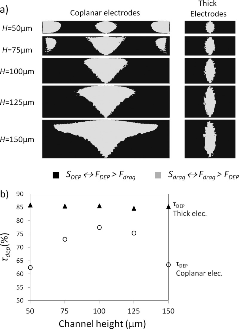
The strategy chosen in this work was to carry out cell trapping using positive DEP. The simulations were carried out using a 3D model for two electrode configurations. In the first one, electrodes were coplanar in the microchannel, whereas in the latter, the electrodes were embedded in the microchannel walls as illustrated in Figs. 2(a) and 2(b). For both configurations, pair electrodes, separated by 200 μm and with identical triangular shape, i.e., isosceles right-angled triangles, were designed. First, we investigated the influence of the microchannel height (H) on cell capture yield as channel depth ranged from 50 to 150 μm. As expected, in both configurations, maxima of electric field gradient were probed between the two electrode tips, thus concentrating maximum of DEP force at the same localization. We also noticed that in coplanar configuration, decreases as the distance to the electrode increases whereas, in thick electrode configuration, the same force remains mainly uniform with z. However, as explained previously, trapping yield depends on the ratio . Indeed, in areas where , we can expect that cell trajectories are dominated by DEP force and cells are trapped at the surface of electrodes. In opposite, for areas where , cell trajectories are dominated by the drag force and therefore cells move around the electrodes without being trapped.
In order to compare capture yield for the different configurations and channel depths, we evaluated from our numerical simulations the surface area Si where both conditions are encountered: represents the surface area where DEP force dominates over drag force, whereas represents the opposite condition. The evolution of and as a function of the channel thickness for both configurations is represented in Fig. 3(a) for a mean flow velocity of 3 mm/s. From these results, we estimated the capture efficiency defined by the ratio and represented in Fig. 3(b). We can notice that for the channel heights chosen here (i.e., ranging from 50 to 150 μm) and when an identical mean flow velocity is used for both configurations, the trapping efficiency obtained with thick electrodes surpasses the one achieved using coplanar electrodes. Moreover, we can highlight a major behavior difference for both configurations. While in the case of thick electrodes the capture yield remains stable when the channel height is increased, in the case of coplanar configuration, we observe a major influence of this parameter on . Indeed, as observed in Fig. 2(d), first increases when 50 μm < H < 100 μm, then decreases for H above 100 μm.
FIG. 3.
(a) Cross section view of competition of DEP vs. drag forces between electrodes tips in various channel height for 3D and 2D electrodes (mean flow velocity of 3 mm/s). (b) τdep as a function of channel height for thick and coplanar electrode configurations for a mean velocity of 3 mm/s.
In thick configuration, as the electric field gradient is generated homogeneously on the entire channel height, is almost independent of H. Therefore, thick electrodes present a major advantage over coplanar configuration as they allow increasing channel thickness without degradation of the capture yield. In the case of thick configuration, increasing the channel height is a solution to increase flow rate and thus to increase capture throughput while preserving capture yield.
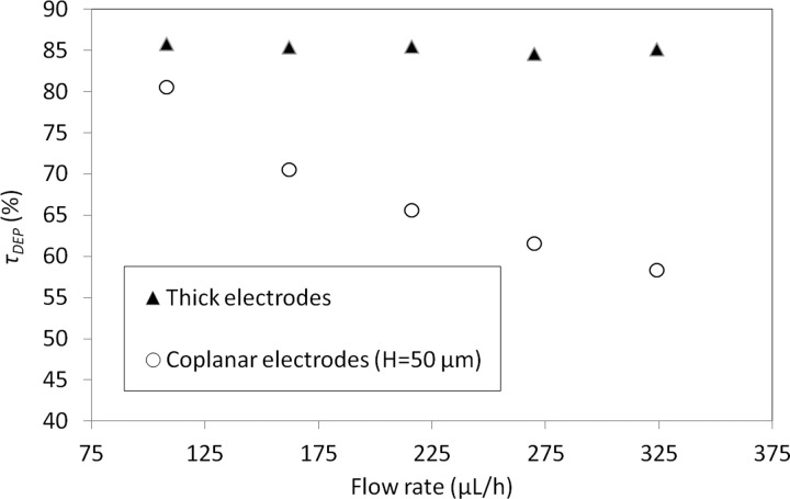
We also compared trapping efficiency for both configurations as a function of flow rate (from 108 to 324 μl/h). For coplanar configuration, all simulations were done for channels presenting an identical channel section (50 μm thick and 500 μm in width), thus the mean flow velocity varies from 1.2 mm/s to 3.6 mm/s. In the case of thick electrodes, simulations were done for channels presenting varying channel section (500 μm wide and from 50 to 150 μm thick channel). In this case, the resulting mean flow velocity remains constant to 3 mm/s for each applied flow rate.
Numerical results reported in Fig. 4 demonstrate that it is possible to keep high capture yield while increasing flow rate by using thick electrode configuration.
FIG. 4.
τdep as a function of applied flow rate for thick and coplanar electrode configurations.
Simulations reported here demonstrate that, for a same mean flow velocity, a larger capture yield is achieved with thick electrodes. This benefit is all the more significant that the electrodes are thicker.
2. Improving cell trapping with thick electrode configurations
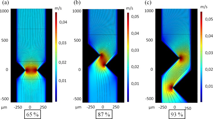
Then, we predicted MDA-MB-231 cell trajectories (using expression (7)) and the capture yield for three different thick electrode geometries: (i) face-to-face, (ii) slightly shifted, and (iii) shifted. For these simulations, we used a 2D model as the electric field gradient generated by thick electrodes is uniform along the channel height. In this model, the influence of top and bottom walls of the system are therefore neglected on the particles motions as already shown in literature.39,40
In the case of the face-to-face configuration, electrodes being symmetrical along the axis of the channel, cells injected in the center of the channel experience low due to their distance to the electrodes. Theoretical capture yield for this geometry was then estimated by calculating the ratio of the number of cell trajectories ending on the electrode over the number of cell trajectories injected at the inlet (Fig. 5).
FIG. 5.
Simulation of velocity fields and trajectories of MDA-MB-231 using an electric field of 3.75 kV/cm at 1 MHz; captured trajectories rate: (a) 65%; (b) 87%; and (c) 93%.
For an applied electric field of 3.75 kV/cm at 1 MHz and a flow rate of 1.5 ml/h (mean flow velocity of 40 mm/s between electrodes), 65% of cells trajectories were captured with face-to-face electrodes. In both shifted designs, electrodes were inserted deeper inside the channel while the width of the channel at the electrode tip location is enlarged. These configurations result in a local fluid velocity lower than for face-to-face geometries and thus lower value of . The results are that cells injected in the center of the channel experience a higher in these configurations compared to the face to face configuration. In shifted configurations, there is also a better coverage of the space compared to the face to face configuration. In the same conditions as previously described, the theoretical capture yield of these shifted configurations was increased and amounted to 96% for the shifted electrodes configuration in which electrodes were inserted beyond the half of the channel.
B. Experimental results
1. Cell trapping efficiency: Face-to-face vs. shifted electrodes
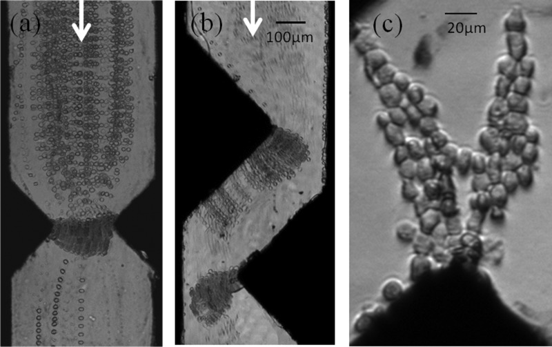
Devices integrating C-PDMS triangular electrodes positioned in the face to face or shifted configurations were experimentally prepared and tested to capture MDA-MB-231 cells at different flow rates. Fig. 6 reports time-lapse stacking of cell trajectories for both configurations for an applied electric field of 3.75 kV/cm at 1 MHz. As explained previously, electric field was chosen to optimize dielectrophoretic forces while avoiding cell lysis, and effectively, no electrical lysis was observed on trapped cells for these conditions. As observed in Fig. 6(c), cells were trapped on electrode tips where the electrophoretic force is maximum compared to the drag force. We can also notice that for both configurations, cell trajectories obtained here experimentally are in good agreement with the trajectories simulated. In both configurations, when the number of trapped cells increases, cells form pearl chains from one electrode to the other. At low flow rate, such as 15 μl/h as reported in Fig. 6(a), for a device integrating face-to-face electrodes, cells' pearl chains participate to cell trapping by creating a barrier. For higher flow rate, pearl chains created on electrodes tips are dragged by the flow along the electrodes and the longest ones tend to detach, as illustrated in Fig. 6(b) with the picture of a shifted electrode configuration under a flow rate of 40 μl/h.
FIG. 6.
Time-lapse stacking of cell trajectories for the 2 configurations (flow direction is from top to bottom): (a) 15 μl/h, (b) 40 μl/h (mean flow velocities between the electrodes are, respectively, 417 and 1111 μm/s); (c) Picture of cell pearl chains formed (3.75 kV/cm at 1 MHz).
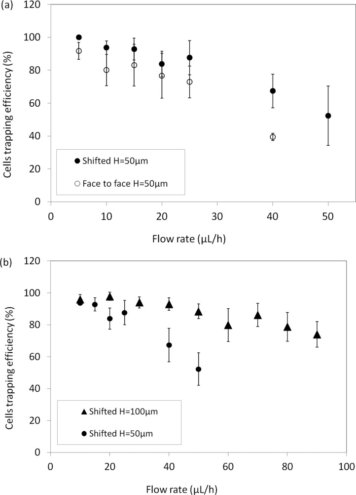
Videomicroscopic recordings of cell behavior near the electrodes tips were performed to evaluate experimental capture yield, calculated by counting the number of cells trapped and the total number of cells flowing during an experiment. Capture yields, for both configurations, are reported in Fig. 7(a) for flow rates ranging from 5 to 50 μl/h. Each experimental point is the mean value of three experiments obtained by following 10 to 50 cells.
FIG. 7.
Percentage of cells trapped on electrode as a function of flow rate (a) for the 2 designs and (b) for shifted electrodes with H = 50 μm and 100 μm (error bars represent mean deviation).
As expected, for a fixed channel height of 50 μm, trapping efficiency decreases as flow rate is increased. However, as predicted by simulations, the shifted configuration appears more efficient than the face-to-face geometry. Indeed, at a flow rate of 5 μl/h, this efficiency is nearly 100% for the shifted electrodes, whereas it amounts to 92% for the face-to-face configurations. At intermediate flow rate, such as 25 μl/h, trapping efficiency achieved 88% and 73% for each configuration, respectively.
However, in order to reach experimental trapping efficiency of the same order of magnitude as in the simulations, we had to work with lower flow rate. This discrepancy can be explained by different reasons. The conductivity value of the cytoplasm used for simulation does not take into account possible leakage of ions from the cytosol through the cell membrane as reported in the literature for similar electric field.41 Besides, due to Joule effect, the rise of temperature may be considered and lead to an increase in the local conductivity. Both effects could result in a decrease of the electric field in the channel due to low C-PDMS conductivity (difference between medium and electrode conductivity being decreased, voltage drop in C-PDMS is raised) leading to a lower DEP force.31 In addition, the electrical connection between gold tracks and C-PDMS may present some defects, also contributing to the reduction of the electric field in the channel during experiments. Finally, devices were simulated in 2D; the mean flow velocity was then considered for calculation, underestimating .
Even if trapping efficiency is an important figure of merit for rare cell capture, the throughput should also be sufficiently high in order to decrease the time of sample treatment. In Fig. 7(b), we report the influence of channel depth (50 and 100 μm) on the experimental capture yield for flow rates up to 80 μl/h, for shifted electrode configuration. We show here that by using thicker electrodes (100 μm), it is possible to maintain a large yield for higher flow rate. Indeed, this yield ranges from 96% to 79% for flow rates ranging from 10 to 80 μl/h. We can deduce that, thanks to thick C-PDMS electrodes, DEP capture throughput can be increased while keeping a large capture yield. This yield is in the same order of magnitude as previously published works42 where yield ranges from 60 to 96% and flow rates ranges from 6 μl/h to 1 ml/h.
The increase of throughput can also be obtained using parallelization. We tested a bipolar configuration to trap cells in parallel microchannels using a minimum of electrical connections. This preliminary experiment demonstrated that we were able to capture HBL-100 and MCF7 cancerous cells in parallel with MDA-MB-231. In this experiment, for the DEP electrodes associated in series (bipolar configuration), we used the maximum voltage available with our instrumentation, i.e., 800 Vpp corresponding to an electric field of 6.7 kV/cm and per channel. This value is larger than the value used to perform capture in a single channel. We assume that this bipolar configuration, where three microchannels are in parallel, increases Ohmic losses, and therefore, only part of the electric field was used to perform DEP. We also carried out reverse transcriptase-quantitative Polymerase chain reaction (RT-qPCR) on lysed cells on-chip after DEP capture in order to demonstrate that molecular integrity was conserved. We were able to detect MCF7 and MDA-MB-231 specific markers (ER1 receptor and vimentin) in the lysate sample. DEP capture using our approach is therefore adapted for molecular downstream analyses.
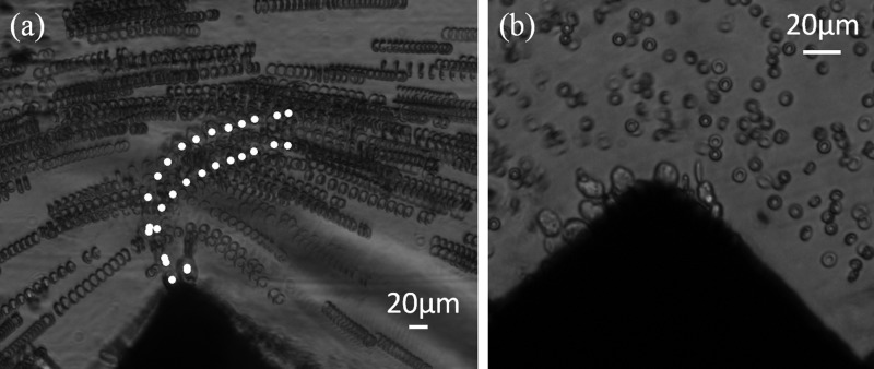
Finally, we performed a preliminary experiment to demonstrate the capacity of these thick C-PDMS electrodes to capture of MDA-MB-231 mixed with Red Blood Cell suspension. MDA-MB-231 were chosen as model for Circulating Tumor Cells. The calculation of the Clausius-Mossotti factors for the two cell populations indicated a range of frequencies of interest for CTC capture between 40 and 100 kHz. The optimum frequency, 90 kHz, was determined experimentally, and we managed to capture selectively CTCs with an applied electric field of 1.25 kV/cm at 90 kHz and for a flow rate of 5 μl/h as illustrated in Fig. 8. Time-lapse stacks show trajectories for both cell populations and demonstrate that RBC flow along the channel, while cancer cells (center of mass labeled in white on Fig. 8(a)) experience that overcomes , thus modifing their trajectories until trapping. In Fig. 8(b), we can clearly observe the trapping of cancerous cells at the tip of the C-PDMS electrode while RBC remain in the fluid stream.
FIG. 8.
Illustration of MDA-MB-231 DEP isolation (1 kV/cm at 90 kHz for 1 to 5 μl/h) from RBC sample for a CTCs concentration ratio of 1:10. (a) Time-lapse stacking: centers of mass of MDA-MB-231 are labeled in white; (b) picture of MDA-MB-231 cells that were trapped on the electrode tip, whereas RBC were not.
V. CONCLUDING REMARKS
Numerical simulations demonstrated here the benefit of the integration of a thick electrode configuration over a coplanar configuration for DEP trapping in terms of efficiency and throughput. Indeed, in the case of a coplanar configuration, it is particularly challenging to increase throughput while preserving large capture efficiency. In opposite, in the case of a thick configuration where thick electrodes are embedded in the microchannel walls, throughput can be easily increased by increasing channel thickness and only slightly affecting capture efficiency. After optimization of three thick electrode configurations (face-to-face, slighly shifted, and shifted) using simulations, we used a composite material C-PDMS composed of carbon nanoparticles in a PDMS matrix, to fabricate thick carbon electrodes embedded in PDMS microchannel walls. C-PDMS presents the advantages of combining properties of both the matrix and doping particles and allows the easy and fast integration of carbon microstructures using soft-lithography approach while preserving O2 plasma bonding properties of PDMS substrate. However, higher voltages are required due to C-PDMS conductivity lower than bulk conductive materials one. In addition, any eventual increase of medium conductivity may be taken into account. Using such 100 μm thick electrodes, we demonstrated trapping efficiencies of 97% at 20 μl/h and 78.7% at 80 μl/h for MDA-MB-231 breast cancer cell line. Other works report continuous separation of cancer cells using DEP at higher flow rate.43–45 In this paper, we demonstrated the interest of C-PDMS to perform cell immobilization which requires to fully compensate the drag force. Having demonstrated the interest of thick C-PDMS based electrodes for such a challenging goal, it would be interesting to evaluate in a future work the performances of this conductive composite for continuous separation of cancer cells.
Finally, we illustrated the performance of this configuration by employing these electrodes for the capture of cancerous cells circulating in a RBC sample. Future work includes the quantification of capture yield of mixture of cancerous cells (MCF7, HBL-100, and MDA-MB-231) with RBC.
ACKNOWLEDGMENTS
Experiments presented here were performed using NanoLyon technological facilities. This work was supported by CNRS, ANR Oncoscreen (ANR-2010-INTB-913), LabEx IMUST, and Région Rhône-Alpes. FST (Faculté des Sciences et des Technologies) and Collegium C2I@Lyon are acknowledged for their contributions to build bio/nano experimental facilities. The authors thank Jérôme Desgouttes and Nicolas Terrier for their technical support.
References
- 1. Dharmasiri U., Witek M. A., Adams A. A., and Soper S. A., Annu. Rev. Anal. Chem. 3, 409 (2010). 10.1146/annurev.anchem.111808.073610 [DOI] [PubMed] [Google Scholar]
- 2. Pratt E. D., Huang C., Hawkins B. G., Gleghorn J. P., and Kirby B. J., Chem. Eng. Sci. 66, 1508 (2011). 10.1016/j.ces.2010.09.012 [DOI] [PMC free article] [PubMed] [Google Scholar]
- 3. Hou H. W., Bhagat A. A. S., Chong A. G. L., Mao P., Tan K. S. W., Han J., and Lim C. T., Lab Chip 10, 2605 (2010). 10.1039/c003873c [DOI] [PubMed] [Google Scholar]
- 4. Cima I., Yee C. W., Iliescu F. S., Phyo W. M., Lim K. H., Iliescu C., and Tan M. H., Biomicrofluidics 7, 11810 (2013). 10.1063/1.4780062 [DOI] [PMC free article] [PubMed] [Google Scholar]
- 5. Gascoyne P. R. C., Wang X.-B., Huang Y., and Becker F. F., IEEE Trans. Ind. Appl. 33, 670 (1997). 10.1109/28.585856 [DOI] [PMC free article] [PubMed] [Google Scholar]
- 6. Martinez-Duarte R., Electrophoresis 33, 3110 (2012). 10.1002/elps.201200242 [DOI] [PubMed] [Google Scholar]
- 7. Shafiee H., Sano M. B., Henslee E. A., Caldwell J. L., and Davalos R. V., Lab Chip 10, 438 (2010). 10.1039/b920590j [DOI] [PubMed] [Google Scholar]
- 8. Yang L., Banada P. P., Chatni M. R., Lim K. S., Bhunia A. K., Ladisch M., and Bashir R., Lab Chip 6, 896 (2006). 10.1039/b607061m [DOI] [PubMed] [Google Scholar]
- 9. Germishuizen W. A., lti C. W., Wirtz R., Johnston M. B., Pepper M., Davies A. G., and Middelberg A. P. J., Nanotechnology 14, 896 (2003). 10.1088/0957-4484/14/8/310 [DOI] [Google Scholar]
- 10. Voldman J., Toner M., Gray M. L., and Schmidt M. A., J. Electrostat. 57, 69 (2003). 10.1016/S0304-3886(02)00120-1 [DOI] [Google Scholar]
- 11. Wang L., Flanagan L., and Lee A. P., J. Microelectromech. Syst. 16, 454 (2007). 10.1109/JMEMS.2006.889530 [DOI] [Google Scholar]
- 12. Iliescu C., Tresset G., and Xu G., Biomicrofluidics 3, 44104 (2009). 10.1063/1.3251125 [DOI] [PMC free article] [PubMed] [Google Scholar]
- 13. Park B. Y. and Madou M. J., Electrophoresis 26, 3745 (2005). 10.1002/elps.200500138 [DOI] [PubMed] [Google Scholar]
- 14. Martinez-Duarte R., Gorkin R. A., Abi-Samra K., and Madou M. J., Lab Chip 10, 1030 (2010). 10.1039/b925456k [DOI] [PubMed] [Google Scholar]
- 15. Voldman J., Gray M. L., Toner M., and Schmidt M. A., Anal. Chem. 74, 3984 (2002). 10.1021/ac0256235 [DOI] [PubMed] [Google Scholar]
- 16. Wang L., Flanagan L. A., Monuki E., Jeon N. L., and Lee A. P., Lab Chip 7, 1114 (2007). 10.1039/b705386j [DOI] [PMC free article] [PubMed] [Google Scholar]
- 17. Tay F. E. H., Yu L., Pang A. J., and Iliescu C., Electrochim. Acta 52, 2862 (2007). 10.1016/j.electacta.2006.09.022 [DOI] [Google Scholar]
- 18. Xing X. and Yobas L., Analyst 140, 3397 (2015). 10.1039/C5AN00167F [DOI] [PubMed] [Google Scholar]
- 19. Hawkins B. G., Smith A. E., Syed Y. A., and Kirby B. J., Anal. Chem. 79, 7291 (2007). 10.1021/ac0707277 [DOI] [PubMed] [Google Scholar]
- 20. Cho Y.-K., Kim S., Lee K., Park C., Lee J.-G., and Ko C., Electrophoresis 30, 3153 (2009). 10.1002/elps.200900179 [DOI] [PubMed] [Google Scholar]
- 21. Henslee E. A., Sano M. B., Rojas A. D., Schmelz E. M., and Davalos R. V., Electrophoresis 32, 2523 (2011). 10.1002/elps.201100081 [DOI] [PubMed] [Google Scholar]
- 22. Deman A.-L., Brun M., Quatresous M., Chateaux J.-F., Frenea-Robin M., Haddour N., Semet V., and Ferrigno R., J. Micromech. Microeng. 21, 095013 (2011). 10.1088/0960-1317/21/9/095013 [DOI] [Google Scholar]
- 23. Niu X. Z., Peng S. L., Liu L. Y., Wen W. J., and Sheng P., Adv. Mater. 19, 2682 (2007). 10.1002/adma.200602515 [DOI] [Google Scholar]
- 24. Becker F. F., Wang X. B., Huang Y., Pethig R., Vykoukal J., and Gascoyne P. R., Proc. Natl. Acad. Sci. U. S. A. 92, 860 (1995). 10.1073/pnas.92.3.860 [DOI] [PMC free article] [PubMed] [Google Scholar]
- 25. Kim Y., Lee J., An J., Lee S. H., and Kim B., J. Mech. Sci. Technol. 23, 3132 (2010). 10.1007/s12206-009-0910-6 [DOI] [Google Scholar]
- 26. Gascoyne P. R. C., Noshari J., Anderson T. J., and Becker F. F., Electrophoresis 30, 1388 (2009). 10.1002/elps.200800373 [DOI] [PMC free article] [PubMed] [Google Scholar]
- 27. Brun M., Chateaux J.-F., Deman A.-L., Pittet P., and Ferrigno R., Electroanalysis 23, 321 (2011). 10.1002/elan.201000321 [DOI] [Google Scholar]
- 28. Patel S., Showers D., Vedantam P., Tzeng T.-R., Qian S., and Xuan X., Biomicrofluidics 6, 34102 (2012). 10.1063/1.4732800 [DOI] [PMC free article] [PubMed] [Google Scholar]
- 29. Pohl H. A., J. Appl. Phys. 22, 869 (1951). 10.1063/1.1700065 [DOI] [Google Scholar]
- 30. Pohl H. A., Dielectrophoresis: The Behavior of Neutral Matter in Nonuniform Electric Fields ( Cambridge University Press, 1978). [Google Scholar]
- 31. Holzner F., Hagmeyer B., Schütte J., Kubon M., Angres B., and Stelzle M., Electrophoresis 32, 2366 (2011). 10.1002/elps.201100026 [DOI] [PubMed] [Google Scholar]
- 32. Sukhorukov V. L., Meedt G., Ku M., and Zimmermann U., J. Electrostat. 50, 191 (2001). 10.1016/S0304-3886(00)00037-1 [DOI] [Google Scholar]
- 33. Jones T. B., Electromechanics of Particles ( Cambridge University Press, 2005). [Google Scholar]
- 34. Han A., Yang L., and Frazier A. B., Clin. Cancer Res. 13, 139 (2007). 10.1158/1078-0432.CCR-06-1346 [DOI] [PubMed] [Google Scholar]
- 35. Sancho M., Martínez G., Muñoz S., Sebastián J. L., and Pethig R., Biomicrofluidics 4, 022802 (2010). 10.1063/1.3454129 [DOI] [PMC free article] [PubMed] [Google Scholar]
- 36. Sukhorukov V. L., Mussauer H., and Zimmermann U., J. Membr. Biol. 163, 235 (1998). 10.1007/s002329900387 [DOI] [PubMed] [Google Scholar]
- 37. Gonzalez C. F. and Remcho V. T., J. Chromatogr. A 1079, 59 (2005). 10.1016/j.chroma.2005.03.070 [DOI] [PubMed] [Google Scholar]
- 38. Cetin B. and Li D., Electrophoresis 32, 2410 (2011). 10.1002/elps.201100167 [DOI] [PubMed] [Google Scholar]
- 39. Zhu J., Tzeng T.-R. J., Hu G., and Xuan X., Microfluid. Nanofluid. 7, 751 (2009). 10.1007/s10404-009-0432-7 [DOI] [Google Scholar]
- 40. Kang K. H., Kang Y., Xuan X., and Li D., Electrophoresis 27, 694 (2006). 10.1002/elps.200500558 [DOI] [PubMed] [Google Scholar]
- 41. Georgiewa R., Donath E., and Gimsa J., J. Electroanal. Chem. Interfacial Electrochem. 276, 255 (1989). 10.1016/0022-0728(89)87269-9 [DOI] [Google Scholar]
- 42. Jin C., McFaul S. M., Duffy S. P., Deng X., Tavassoli P., Black P. C., and Ma H., Lab Chip 14, 32 (2014). 10.1039/C3LC50625H [DOI] [PubMed] [Google Scholar]
- 43. Gupta V., Jafferji I., Garza M., Melnikova V. O., Hasegawa D. K., Pethig R., and Davis D. W., Biomicrofluidics 6, 24133 (2012). 10.1063/1.4731647 [DOI] [PMC free article] [PubMed] [Google Scholar]
- 44. Shim S., Stemke-Hale K., Tsimberidou A. M., Noshari J., Anderson T. E., and Gascoyne P. R. C., Biomicrofluidics 7, 11807 (2013). 10.1063/1.4774304 [DOI] [PMC free article] [PubMed] [Google Scholar]
- 45. Markx G. H., Talary M. S., and Pethig R., J. Biotechnol. 32, 29 (1994). 10.1016/0168-1656(94)90117-1 [DOI] [PubMed] [Google Scholar]


