Abstract
Microfluidic impact printing has been recently introduced, utilizing its nature of simple device architecture, low cost, non-contamination, and scalable multiplexability and high throughput. In this paper, we have introduced an impact-based droplet printing platform utilizing a simple plug-and-play microfluidic cartridge driven by piezoelectric actuators. Such a customizable printing system allows for ultrafine control of droplet volume from picoliters (∼23 pl) to nanoliters (∼10 nl), a 500 fold variation. The high flexibility of droplet generation can be simply achieved by controlling the magnitude of actuation (e.g., driving voltage) and the waveform shape of actuation pulses, in addition to nozzle size restrictions. Detailed printing characterizations on these parameters have been conducted consecutively. A multiplexed impact printing system has been prototyped and demonstrated to provide the functions of single-droplet jetting and droplet multiplexing as well as concentration gradient generation. Moreover, a generic biological assay has also been tested and validated on this printing platform. Therefore, the microfluidic droplet printing system could be of potential value to establish multiplexed micro reactors for high-throughput life science applications.
I. INTRODUCTION
Droplet generation has been recently adapted to numerous biological and biochemical applications in both academia and industry. These miniscule liquid carriers, often serving as micro reactors or capsules, offer several distinct advantages over their conventional counterparts, including significantly high throughput, substantially lower reagent consumption, increased reaction efficiency due to reduced diffusion length, and massive multiplexability (i.e., the droplets can be generated simultaneously or sequentially through a physically multichannel system).1–4 Such advantages have become an impetus to a wide array of research and industrial applications, where the system throughput and reagent consumptions are two limiting factors. A number of droplet generation techniques have been previously established, among which microfluidic and inkjet printing are the most commonly used for their high throughput and high efficiency. For the microfluidic approaches, flow-focusing methods and T-junction channels have been frequently adapted for high-throughput generation (>1 kHz) of picoliter- to nanoliter-sized droplets.5,6 The flow-focusing devices have been used for microencapsulations,7 ionic fluid emulsion generation,8 and double emulsions.9,10 T-junction configurations have been used for generating microreactors,11 synthesizing multifunctional particles,12 and forming droplets with alternating compositions.13 Both of the methods are primarily based on shear flow, and the isolated liquid contents carried by an immiscible fluid in individual droplets can be further processed and analyzed. For example, Rustem group14 has demonstrated the power of a flow-focusing method in determination of enzymatic kinetics on a millisecond timescale with nanoliter reagents. Moreover, Lee group has developed an alternative flow-focusing platform for continuous generation of monodispersed lipid vesicles of 20–110 μm in diameter, and has demonstrated the cell-free, in vitro synthesis of proteins within lipid vesicles as an initial step towards the development of an artificial cell.15–17 On the other hand, the inkjet printing provides an alternative to the microfluidic approaches, which is simple to implement and easy to scale up. Several reviews have included the detailed discussion on its operation principle, functions, and applications.18–20 We have restricted our discussion only to the drop-on-demand (DOD) printing, which is typically considered as one type of inkjet printing, but becomes very popular for biomaterial and biological applications. A research-grade material deposition system, e.g., Dimatix (Fuji Film) or Jetlab (MicroFab) printer, has been frequently utilized to produce various biomaterial patterns for potential biological applications. In particular, Andreescu group21 used the Dimatix DMP-2800 printer to fabricate enzymatic sensors with layer-by-layer disposition of chitosan, alginate, and enzyme onto a filter paper for colorimetric detection of phenolic compounds. More recently, by utilizing a Jetlab inkjet platform, the Yu group22 demonstrated quantitative analysis of polymerase chain reactions (PCR) in picoliter droplet-in-oil arrays with no crosstalk and minimal evaporation. A variety of biomaterials have been deposited by these drop-on-demand printing systems, in which the piezoelectric actuation has been primarily utilized instead of the thermal expansion principle. Considering the high price tag of the dedicated materials printers, other groups modified low-cost office printers to achieve similar functions. For example, Jang group23 modified an office inkjet printer (Canon Pixma IP1300) to deposit an ammonium solution into desired patterns on a PET film for biomolecule detection from live cells.
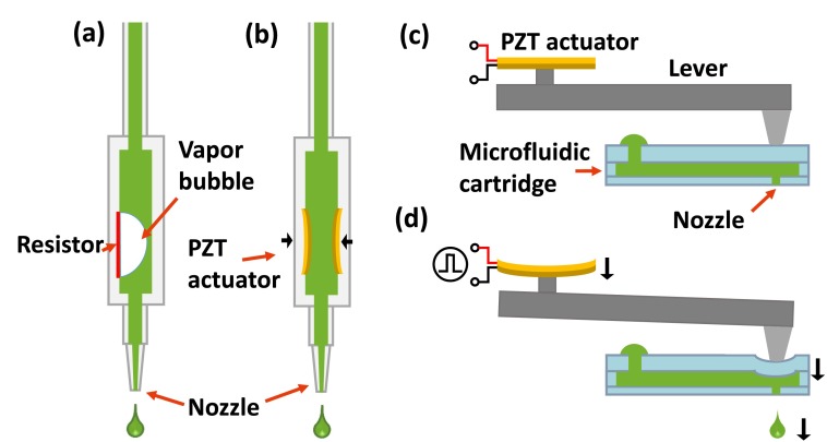
In general, the microfluidic approaches offer high throughput (∼kHz) and high uniformity (1%–3% difference in diameter) at a low unit cost.24 However, it requires a dedicated fabrication process for microchip development and also needs specialized external controls and drives (e.g., microvalves, pumps, and electric or laser controller) to spatially and temporally manipulate discrete droplets. Especially, these manipulations are highly suited for single-cell analysis of preselected cell subpopulations.25 In comparison, DOD printing is commercially available and easy to use. However, it is nearly impossible to configure for custom applications because of its fixed cartridge design with large loading and dead volumes and its difficulty in multiplexing, in addition to high equipment and cartridge costs. In our previous work, we have proposed an interchangeable droplet printing strategy, known as microfluidic impact printing, in which a conventional dot-matrix printer head with a linear array of electromagnetic driven pins has been custom-modified to strike onto microfluidic cartridge membranes for multiplexed droplet generation.26 The key innovation of this kind of printer design is that all the printer components become modular and separable with no crosstalk, in particular, the microfluidic cartridge design becomes simple to fabricate and easy to standardize for various applications at an extremely low cost, as compared to the integrated cartridge design implemented in commercial inkjet printers (Fig. 1). Moreover, the microfluidic cartridge has a low dead volume in a sub-microliter range, which is highly efficient for applications with precious or limited biochemical reagents/samples. However, the dot-matrix printer head has limited flexibility in the pin actuation design. For instance, both the actuation distance and magnitude are fixed by default, and therefore, control of the droplet generation becomes a challenging issue when different sizes/volumes of droplets are highly desired. This grows more problematic when precise mixing of more than two liquids is required, where each pin actuator has different tolerances on actuation distance and generates droplet volume with a certain variation.
FIG. 1.
Schematic illustration shows the working principles of drop-on-demand inkjet printing. Droplets are ejected from a nozzle under pressure waves exerted internally or externally, which can attribute to (a) vaporized bubble by a heating resistor (in thermal inkjet), (b) mechanical stroke from integrated actuator (in piezoelectric inkjet), or (c) and (d) physical stroke from a separable actuator (in microfluidic impact printing), where (c) and (d) represent the printing states before and after mechanical loads, respectively. Importantly, for the traditional inkjet counterparts in (a) and (b), the ink flows through a cartridge with direct contact with the actuator, while for the microfluidic impact printer ((c) and (d)), the ink would never touch the printing actuator through an interchangeable cartridge, avoiding potential cross-contamination issues.
For the first time, we established a microfluidic impact printing platform with a series of individually actuated piezoelectric actuators for high-throughput droplet generation. As compared to the dot matrix printing, piezoelectric printing offers easy yet high-precision control over droplet generation. Moreover, the expandable design of the piezoelectric actuators allows for generation of complex combinatorial materials, which can be highly useful for building combinatorial libraries and designing multi-step biochemical reactions. Utilizing the high controllability in deformation of the piezoelectric actuator, the printer can precisely control the volume of the droplet by adjusting voltage amplitudes and waveform shapes. Table I compares the piezoelectric microfluidic impact printing with some typical droplet generation methods. Combining microfluidic cartridges with nozzles of discrepant diameter, the volume of each droplet can be regulated in a wide range for different purposes. Based on the successful system demonstration and characterization, we have printed a quantitative protein assay with 128-fold concentration gradient profiles, with no crosstalk and minimal evaporation. We believe that this piezoelectric-driven droplet impact printer can provide a generic platform to produce multiplexed pico-/nanoliter droplets for a variety of biological and biochemical applications in a high-throughput and high-precision manner.
TABLE I.
Comparison of different droplet generation methods.
| Droplet generation technology | Advantages | Disadvantages |
|---|---|---|
| Microfluidic method | 1. High throughput (1 k–87 kHz, 1–8 channels) | 1. Difficult to isolate single droplet, no position control |
| 2. Large liquid viscosity range | 2. Dedicate fabrication of chip | |
| 3. Control of droplet volume | ||
| 4. Low dead volume | ||
| 5. Good biocompatibility | ||
| Commercial DOD inkjet printing | 1. High throughput (1 k–20 k Hz, 3–6 channels) | 1. Low biocompatibility for thermal inkjet printing |
| 2. Direct operation on single droplet with position/composition control | 2. High cost of cartridge, need of wash | |
| 3. Limited viscosity range (dynamic viscosity: 2–30 cp for DMP; less than 20 cp for Microfab) | ||
| 4. Large dead volume | ||
| Piezoelectric microfluidic impact printing | 1. Multiple channels expandability (4–12 channels) | 1. Low frequency: less than 200 Hz |
| 2. Direct operation on single droplet with position/composition control | 2. Limited viscosity range (dynamic viscosity < 14 cp) | |
| 3. Low-cost and disposable cartridge | ||
| 4. Control of droplet volume | ||
| 5. Low dead volume | ||
| 6. Good biocompatibility |
II. WORKING PRINCIPLE
Microfluidic impact printing emphasizes on the concept of designing a simplified microfluidic cartridge, which can be easily expanded for multiplexing and customized for different applications. Meanwhile, the actuation of the printer head is configured as plug-and-play without directly contacting the working fluid. In particular, the microfluidic cartridge has a three-layer stack of microfluidic structures; i.e., the top layer is composed of deformable actuation membranes and injection reservoirs, the middle layer contains connection channels, and in the bottom layer are printing nozzles, all made of flexible polymeric materials, as shown in Figs. 1(c) and 1(d). As a piezoelectric-driven impact actuator strikes on the membrane, the fluid inside is accelerated bi-directionally, both towards the nozzle and away to the reservoir. The majority of the summative volume of liquid that is propelled towards the nozzle forms a droplet which is then ejected from the nozzle as it prints. The volume of the droplet can be predicted by the following equation (see supplementary material Eqs. (A1)–(A5) for the detailed mathematical derivation):27
| (1) |
Vi is the volumetric displacement caused by the membrane deformation under the impact actuator, while Rn and Rr represent the flow resistances of the microfluidic paths towards the nozzle and the reservoir, respectively. In addition, di indicates the diameter of the impact chamber, and s is the stroke of the impact actuator, from which the overall volume displacement can be derived. It is worth noting that, excepting the stroke (s), the rest parameters are structurally related parameters to determine droplet size, which can be controlled through the microfluidic cartridge design.
In addition to the volume displacement, the fluid has to gain adequate kinetic energy to overcome the surface tension prior to breaking through the nozzle, which can be derived from the inertia of the liquid. According to a prior art,28 the minimum velocity of liquid required to exceed the surface tension limit and to form a departed droplet can be estimated. Here, σ is the surface tension coefficient, and ρ is the fluid density. In order to provide the necessary fluidic inertia, the impact actuation needs to be accelerated to a critical speed (Ui), which can be predicted through the following equation (see supplementary material Eq. (A10) for the detailed mathematical derivation):27
| (2) |
It means that there exists a minimum velocity of the impact actuator for the droplet generation.
III. METHODS
A. System design
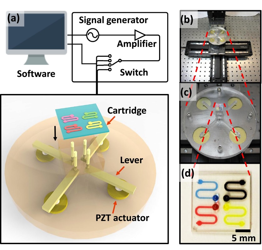
As mentioned previously, the microfluidic impact printer includes an interchangeable microfluidic cartridge, an impact printer head, a 3-axis travelling stage with external controller, and a custom user interface, as shown in Fig. 2. The 3-axis traveling stage (Thorlabs) has a maximum motion speed of 300 mm/s, and positioning repeatability of 0.25 μm. The control software has been developed to simultaneously coordinate the movement of the traveling stage and the actuation of each individual printer head. The control signal is first used to select the printing channel through a custom-made, multi-channel, switching circuitry. An additional control line triggers a pulse through a function generator (33220, Agilent), amplified by a piezoelectric amplifier (EPA-104, Piezo System) to become the driving signal, while the stage is moving accordingly under the control of software.
FIG. 2.
(a) Illustration of the microfluidic impact printing system (note: the individual components are shown prior to the assembly), (b) and (c) views of the printer head with a microfluidic cartridge fixed onto the 3-axis travelling stage, and (d) the microfluidic cartridge loaded with 4 distinct color dyes.
For individual impact actuators, low-cost piezoelectric disks (AB2726B, Digi-key) have been used as the actuation source attached with a steel lever of 38 mm in length and 2 mm in width, which drives a custom-made steel pin of 0.2 mm in diameter mounted perpendicularly to the end of the steel lever. The displacement-amplification lever mechanism has been utilized to magnify the stroke and improve the kinetic velocity of the actuator by 10 fold which is confined by the limited deformation of the piezoelectric disks. Moreover, this structure can help eliminate redundant spacing between adjacent pins for a more compact design of multiplexed printer heads. As shown in Fig. 2(c), a multichannel microfluidic cartridge has been fixed onto a supporting stage with the actuating pins placed underneath without separation. Under such an interchangeable design, the liquid can be pushed out from the microfluidic cartridge nozzle without coming into direct contact with the printer head, enabling the plug-and-play and non-contamination features of the printer. Then, the ejected droplets, departed from the nozzle, travelled in air for about 2 mm before landing onto the substrate.
B. Microfabrication of the microfluidic cartridge and the microwell array
As the key component of the microfluidic impact printer, the interchangeable microfluidic cartridge is intended to be simple to fabricate and easy to customize with standard, modular designs. As previously described, it consists of three polymeric layers. A 100 μm-thick Polydimethylsiloxane (PDMS) film used as bottom layer was prepared by mixing the silicone elastomer base and curing agent (SYLGARD 184, Dow Corning) at a ratio of 10:1, and spinning on a glass slide. The film was then thermally cured at 120 °C for 15 min. Afterwards, a CO2 laser (Universal Laser Systems, VersaLaser 2.30) was used to drill the nozzle on the PDMS film. A commercial silicone film (Rogers Corporation Bisco™ HT-6240) with a 254 μm thickness was also cut by the laser to fabricate the middle channel layer and the top deformed layer. Eventually, these three layers were bonded together after oxygen plasma treatment (at 90 W for 30 s, Diener electronic). A microwell array was prepared as a substrate for protein droplet reaction. 66 microwells with 1 mm diameter were fabricated on a 760 μm thick silicone sheet (Rogers Corporation) with the CO2 laser, and bonded to a 25 × 75 mm glass slide with the same oxygen plasma treatment.
C. Reagents
Silicon oil used in drop-size measurement was purchased from Scientific (Product No. S159–500). Mineral oil was purchased from Sigma-Aldrich (M5904). Bicinchoninic acid (BCA) protein assay kit (Thermo Scientific Pierce, Product No. 23225) used in the protein assay contains two reagents: Reagent A, containing sodium carbonate, sodium bicarbonate, bicinchoninic acid, and sodium tartrate in 0.1 M sodium hydroxide; and Reagent B, containing 4% cupric sulphate. Prior to assaying, a working reagent (WR) was prepared by mixing Reagents A and B in a 50:1 ratio as a detection reagent. Bovine serum albumin (BSA, Sigma-Aldrich) was dissolved in DI water to a concentration of 2000 μg/ml. Soluble dyes (Jacquard iDye Natural Fabric Dye No. 451 Blue and No. 449 Red, No.447 yellow and No.454 black) were prepared in concentrations of 1.5 g/l by dissolving dry powders in dimethyl sulfoxide (DMSO).
D. Generation of concentration gradient
For ease of drop-number calculations, we adopted an evaporation-rehydration method to create a concentration gradient of BSA droplets, during which a series of ascending numbers of aqueous BSA protein droplets were dried first and then rehydrated with equal amounts of Phosphate-Buffered Saline (PBS) solution. This method was verified experimentally by assaying equal volumes of BSA solution created by both conventional manual dilution and the evaporation-rehydration dilution method, which contains the same amount of active BSA components. The two solutions were first printed into silicone oil to form droplets, and then measured under a microscope. The volume of a BSA droplet in comparison with that of a PBS and WR mixed droplet is 2.25nl ± 18pl and 9.47nl ± 97nl, respectively. After measurements, BSA droplets were printed into a horizontal row of wells in a binary pattern, i.e., droplet number of 1, 2, 4, 8,…, 128, accordingly. After 5 min, the water content in all BSA droplets evaporated, and the dried protein contents remained in the wells, followed by which the same volumes of PBS and WR (31 drops for each) were printed in a sequential pattern into each well. After that, mineral oil was manually dispensed on top of the well array to prevent further evaporation. The array was then covered by a glass slide and incubated at room temperature for 30 min before imaging.
E. Imaging and data analysis
An inverted microscope (EVOS, Life Technologies) was used to measure the size of droplets in oil and on a glass substrate. A desktop scanner (Onetouch 7300 USB, Visioneer) was used to scan the image of the protein assay in the microwell array on a glass slide at 1000 dpi. For colorimetric analysis of the BCA protein assay, the parameter of saturation intensity was selected to characterize the image results, as it was closely correlated with BSA concentrations.29 Specifically, scanned images were transformed into numerical color values and averaged over a freely selectable square area (3 × 3 pixels) using a color picker tool in a PC image processing software. Averaged saturation intensity of 3 freely selected square areas within the area of each individual microwell was plotted against the corresponding designed concentrations.
IV. RESULTS AND DISCUSSION
A. Geometric control of droplet volume
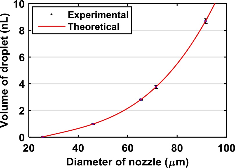
As stated above, the structural parameters in the microfluidic cartridge can be designed and tuned for different sizes of droplet generation, for the fluid distribution under forced displacement is determined by them. As predicted by Poiseuille's equation, the fluidic resistance towards the printer nozzle (Rn) follows a 4th order relationship with the nozzle diameter, which can be adjusted during the microfabrication process. In order to minimize droplet evaporation and improve measurement accuracy, aqueous droplets have been printed into an oil phase inside a petri dish. Fig. 3 shows the printed droplets with increased volume from 23.4 pl (35.3 μm) to 8.90 nl (255.1 μm), as the nozzle openings change from 25.7 μm to 91.5 μm. Here, the dwell time is defined as the pulse width of the driving electrical signals. As expected, the nozzle size has strong influence on droplet volume through the change of flow resistance distribution in the microfluidic cartridge. The experimental data match well against the 4th polynomial curve in Fig. 3, as can be theoretically predicted by Eq. (A6),27 which indicates a straightforward method to tune the droplet volume in a wide range by nozzle size variation.
FIG. 3.
Measurement results of the droplet volume vs. nozzle diameter, given a dwell time of 1 ms and driving voltage at 120 V.
B. Electrical control of the droplet volume
The piezoelectric actuators offer direct electrical control of droplet size in the microfluidic impact printer. Notably, once the geometrical parameters of the microfluidic cartridge are completely set, the electrical control becomes a more convenient way to fine-tune the droplet volume. In this study, we have investigated the influence of the driving voltage and the pulse duration over the generated droplet size.
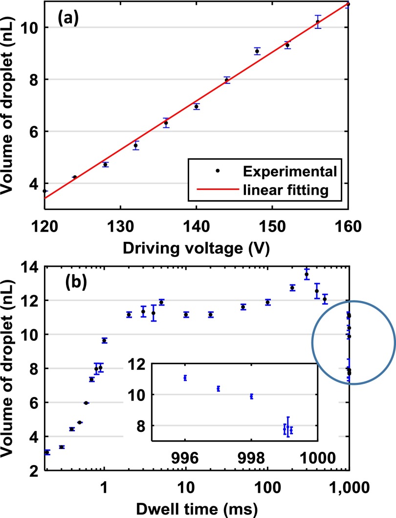
In principle, the driving voltage of the piezoelectric actuators has a linear relationship with the stroke, which determines the overall volumetric displacement of the impact chamber. In our actuator setup, the linear response of the pin is measured at 11.7 μm/V without a load. As shown in Fig. 4(a), the droplet size is linearly increased with the amplitude of driving voltage, which is in consistency with Eq. (1). Fig. 4(b) summarizes the droplet volume vs. dwell time of the actuation pulse under a 1 Hz actuation frequency. It shows a triphasic trend in the measurements. In particular, with a short pulse dwell time (t < 2 ms), the droplet dimension grows monotonically with the rising actuation time. This can be explained because as the piezoelectric actuator pushes and retracts during a short actuation period, the fluid inside the impact chamber has been squeezed, but not completely ejected, due to fluidic viscosity and channel compliance.30,31 Thus, part of the displaced fluid will be sucked back before merging into the departed droplet as soon as the actuator withdraws. For an intermediate dwell time (2 ms < t < 996 ms), the droplet size presents independence from the pulse duration with a limited range of fluctuation (less than 2%), as the majority of the displaced volume has been ejected as a departed droplet from the nozzle. Finally, as the dwell time continues increasing (t is above 997 ms in 1 Hz printing), there is not enough time for the impact chamber to refill completely, and therefore, the refilling process becomes the limiting factor, restricting the amount of ejected volume. As the dwell time is set to greater than 999 ms, a second droplet cannot be produced due to insufficient refilling time. In brief, for droplet generation stability, a duty cycle of 2%–99% is preferred as the droplet size becomes independent of the dwell time. Moreover, the ejection and the refilling time become limiting factors of the printing frequency.
FIG. 4.
Experimental results of printed aqueous droplets on a silanized glass substrate operated under a 1 Hz printing speed: (a) droplet volume vs. driving voltage (at a dwell time of 1 ms), and (b) droplet volume vs. dwell time of the actuation pulse (at an actuation voltage of 120 V, the inset is an enlarged view of the data in the circle).
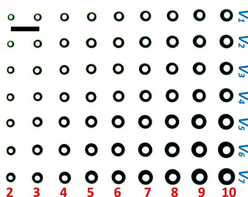
Based on the above electrical characterization results, we have come up with the volumetric control strategy of the droplet volumes, i.e., varying the driving voltage and the number of ejections while keeping the dwell time constant (2 ms). Fig. 5 shows a droplet array with the volume variation from 2.7 nl (in the top left corner) to 47.6 nl (in the bottom right corner). Specifically, in the x-axis, the number of ejections is varied from 2 to 10, while in the y-axis, the voltage has been increased from 88 V to 126 V.
FIG. 5.
Demonstration of volumetric control of the droplet array. In the x-axis, the number of ejections varied from 2 to 10, while in the y-axis, the voltage varies from 88 V to 126 V (scale bar: 1 mm).
C. Multiplexed printing
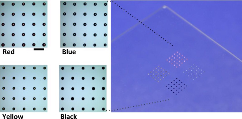
One of the key features of the microfluidic cartridge in impact printing is the simple scalability in multiplexing. It can be highly beneficial to biological and biochemical applications where complex reagents and media are frequently encountered, e.g., proteins, cells, extracellular matrices, and signaling molecules.32 To illustrate the applicability of microfluidic impact printing, we have built a 4-channel printer prototype to deposit arbitrary microdroplet patterns and combinations on solid substrates at a printing frequency of 100 Hz. The 4 different channels in the microfluidic cartridge can be individually loaded with the desired chemicals using a standard pipetting procedure. Here, DMSO solutions with 4 color dyes are used for their low evaporation rates. It is well known that the smaller droplets experience faster evaporation rates as their surface-area-to-volume ratio is larger. To alleviate the evaporation issue of a minute droplet volume, we have either immersed the substrate into oil after printing or directly print droplets into an oil film. A printing program is set to automatically produce arrayed micropatterns and then command the four printing channels to generate drops upon the request sequence. As a result, a matrix pattern, as shown in Fig. 6, is generated by software and built on a silanized glass substrate by microfluidic impact printing.
FIG. 6.
Photos of a color matrix printed 1 mm apart with four solutions on a silanized glass. The solutions are red (top left), blue (top right), yellow (bottom left), and black (bottom right) dye dissolved in DMSO (scale bar: 1 mm).
D. Application: Concentration gradient generation
Furthermore, with the high-stability and high-precision control of droplet printing, the microfluidic impact printer can be utilized for the generation of arbitrary chemical gradients with high efficiency. As compared to conventional preparation protocols, the printing method consumes significantly less reagent and can be adapted to any substrates, without involving any additional steps. In particular, for many biological and biochemical assays, concentration gradient generation has been a routine practice and a critical preparation step where samples are required to be diluted into a wide range of concentrations.33,34 We have built a demonstration on droplet generation of a discrete logarithmic concentration gradient of BSA, and have analyzed the concentration of BSA in the droplet arrays with a BCA protein assay. A binary gradient of BSA concentrations has been designed and deposited in a droplet array format, followed by adding a second WR to report in a colorimetric way. Total volume of 1.8 μl of the BSA solution is consumed for the entire droplet array, at least an order of magnitude less than that of the conventional microtiter plates (on the order of 100 μl)35 and the microfluidic approaches (on the order of 10 μl).36
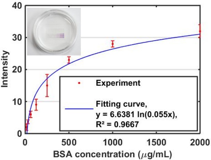
Fig. 7 summarizes the quantitative colorimetric readouts of the printed droplet array with a concentration gradient of BSA built inside, in which the concentration profiles range from 16 μg/ml to 2000 μg/ml. The measurement results are based on the average of triplicate experiments over each droplet, and the standard derivations have also been calculated accordingly. As can be seen, BSA concentration and reflectance intensity follow a natural logarithm relationship, which shows consistency compared with the conventional measurement for reflectance detection.37,38 Aside from the substantially reduced chemical consumption, the reaction time within the miniature droplets (in a nl range) is considerably reduced from 2 h to 30 min at room temperature due to the short diffusion length (on the order of 100 μm).35
FIG. 7.
Quantitative colorimetric readouts of the printed droplet array with a concentration gradient of BSA built inside. The inset is a photo of a BCA sample. The plotted results are averaged measurements graphed with standard derivations from triplicate experiments.
V. CONCLUSIONS
In this article, we have implemented a droplet generation platform based on the microfluidic impact printing technology, where low-cost piezoelectric actuators have been utilized as the impact forces. The modular microfluidic cartridge composed of all polymeric material provides a new, simple means for chemical loading and droplet generation with interchangeability, low cost, non-contamination, and multiplexability. The driving voltage, dwell time, and nozzle size can be controlled, resulting in user-friendly manipulation of high-precision droplet sizes, varying from picoliter to nanoliter. A large concentration gradient (16–2000 μg/ml) has been generated using this microfluidic printing platform, and a protein assay has been implemented and measured colorimetrically. Compared with the conventional and microfluidic quantitative assay platforms, this novel droplet generation system can create arbitrary dilution ratios and reagent combinations by a simple matrix design using custom-made software. In summary, the piezoelectric-driven droplet impact printing system, with a low-cost, plug-and-play microfluidic cartridge, is capable of performing high-precision, high-throughput droplets generation for quantitative molecular analysis with minimal reagent costs.
ACKNOWLEDGMENTS
This work has been supported in part by National Science Foundation Awards ECCS-0846502 and DBI-1256193 to T.P., in addition to National Institutes of Environmental Health Sciences of NIH Superfund Research Program (No. P42ES004699). J.F. acknowledges a fellowship support from the Howard Hughes Medical Institute Integrating Medicine into Basic Science (HHMI-IMBS) Training Program at UC Davis. B.L. acknowledges support from the Oversea Academic Training Funds, University of Science and Technology of China (OATF, USTC). Authors would like to thank Dr. Shirley J. Gee, Dr. Christophe Morisseau, Dr. Candace S. Bever, and Dr. Bruce D. Hammock (the Department of Entomology) for generously providing the BCA kits, Zidong Li for mechanical design, Zixuan Liang for programming, and Samantha Kennedy for sentence refinement.
References
- 1. Szostak J. W., Bartel D. P., and Luisi P. L., Nature 409(6818), 387 (2001). 10.1038/35053176 [DOI] [PubMed] [Google Scholar]
- 2. Leamon J. H., Link D. R., Egholm M., and Rothberg J. M., Nat. Methods 3(7), 541 (2006). 10.1038/nmeth0706-541 [DOI] [PubMed] [Google Scholar]
- 3. Matosevic S., Bioessays 34(11), 992 (2012). 10.1002/bies.201200105 [DOI] [PubMed] [Google Scholar]
- 4. Shen F., Du W., Kreutz J. E., Fok A., and Ismagilov R. F., Lab on a Chip 10(20), 2666 (2010) 10.1039/c004521g. [DOI] [PMC free article] [PubMed] [Google Scholar]
- 5. Teh S.-Y., Lin R., Hung L.-H., and Lee A. P., Lab Chip 8(2), 198 (2008). 10.1039/b715524g [DOI] [PubMed] [Google Scholar]
- 6. Thorsen T., Roberts R. W., Arnold F. H., and Quake S. R., Phys. Rev. Lett. 86(18), 4163 (2001). 10.1103/PhysRevLett.86.4163 [DOI] [PubMed] [Google Scholar]
- 7. Takeuchi S., Garstecki P., Weibel D. B., and Whitesides G. M., Adv. Mater. 17(8), 1067 (2005). 10.1002/adma.200401738 [DOI] [Google Scholar]
- 8. Wang W.-H., Zhang Z.-L., Xie Y.-N., Wang L., Yi S., Liu K., Liu J., Pang D.-W., and Zhao X.-Z., Langmuir 23(23), 11924 (2007). 10.1021/la701170s [DOI] [PubMed] [Google Scholar]
- 9. Nie Z., Li W., Seo M., Xu S., and Kumacheva E., J. Am. Chem. Soc. 128(29), 9408 (2006). 10.1021/ja060882n [DOI] [PubMed] [Google Scholar]
- 10. Yeh C.-H., Zhao Q., Lee S.-J., and Lin Y.-C., Sens. Actuators, A 151(2), 231 (2009). 10.1016/j.sna.2009.02.036 [DOI] [Google Scholar]
- 11. Cygan Z. T., Cabral J. T., Beers K. L., and Amis E. J., Langmuir 21(8), 3629 (2005). 10.1021/la0471137 [DOI] [PubMed] [Google Scholar]
- 12. Okushima S., Nisisako T., Torii T., and Higuchi T., Langmuir 20(23), 9905 (2004). 10.1021/la0480336 [DOI] [PubMed] [Google Scholar]
- 13. Zheng B., Tice J. D., and Ismagilov R. F., Anal. Chem. 76(17), 4977 (2004). 10.1021/ac0495743 [DOI] [PMC free article] [PubMed] [Google Scholar]
- 14. Song H. and Ismagilov R. F., J. Am. Chem. Soc. 125(47), 14613 (2003). 10.1021/ja0354566 [DOI] [PMC free article] [PubMed] [Google Scholar]
- 15. Huebner A., Sharma S., Srisa-Art M., Hollfelder F., and Edel J. B., Lab Chip 8(8), 1244 (2008). 10.1039/b806405a [DOI] [PubMed] [Google Scholar]
- 16. Teh S.-Y., Khnouf R., Fan H., and Lee A. P., Biomicrofluidics 5(4), 044113 (2011). 10.1063/1.3665221 [DOI] [PMC free article] [PubMed] [Google Scholar]
- 17. Tan Y.-C., Hettiarachchi K., Siu M., Pan Y.-R., and Lee A. P., J. Am. Chem. Soc. 128(17), 5656 (2006). 10.1021/ja056641h [DOI] [PubMed] [Google Scholar]
- 18. Martin G. D., Hoath S. D., and Hutchings I. M., J. Phys.: Conf. Ser. 105(1), 012001 (2008). 10.1088/1742-6596/105/1/012001 [DOI] [Google Scholar]
- 19. Derby B., Science 338(6109), 921 (2012). 10.1126/science.1226340 [DOI] [PubMed] [Google Scholar]
- 20. Basaran O. A., Gao H., and Bhat P. P., Annu. Rev. Fluid Mech. 45, 85 (2013). 10.1146/annurev-fluid-120710-101148 [DOI] [Google Scholar]
- 21. Alkasir R. S. J., Ornatska M., and Andreescu S., Anal. Chem. 84(22), 9729 (2012). 10.1021/ac301110d [DOI] [PubMed] [Google Scholar]
- 22. Sun Y., Zhou X., and Yu Y., Lab Chip 14(18), 3603 (2014). 10.1039/C4LC00598H [DOI] [PubMed] [Google Scholar]
- 23. Oh W. K., Kim S., Shin K. H., Jang Y., Choi M., and Jang J., Talanta 105(15), 333 (2013). 10.1016/j.talanta.2012.10.050 [DOI] [PubMed] [Google Scholar]
- 24. Joensson H. N. and Svahn H. A., Angew. Chem. Int. Ed. 51(49), 12176 (2012). 10.1002/anie.201200460 [DOI] [PubMed] [Google Scholar]
- 25. Reginald Beer N., Hindson B. J., Wheeler E. K., Hall S. B., Rose K. A., Kennedy I. M., and Colston B. W., Anal. Chem. 79(22), 8471 (2007). 10.1021/ac701809w [DOI] [PubMed] [Google Scholar]
- 26. Ding Y., Huang E., Lam K. S., and Pan T., Lab Chip 13(10), 1902 (2013). 10.1039/c3lc41372a [DOI] [PMC free article] [PubMed] [Google Scholar]
- 27.See supplementary material at http://dx.doi.org/10.1063/1.4928298E-BIOMGB-9-001505 for the detailed mathematical derivation.
- 28. Derby B., Annu. Rev. Mater. Res. 40, 395 (2010). 10.1146/annurev-matsci-070909-104502 [DOI] [Google Scholar]
- 29. Abe K., Suzuki K., and Citterio D., Anal. Chem. 80(18), 6928 (2008). 10.1021/ac800604v [DOI] [PubMed] [Google Scholar]
- 30. Yang A.-S., Yang J.-C., and Hong M.-C., J. Micromech. Microeng. 16(1), 180 (2006). 10.1088/0960-1317/16/1/024 [DOI] [Google Scholar]
- 31. Riefler N. and Wriedt T., Part. Part. Syst. Char. 25(2), 176 (2008). 10.1002/ppsc.200700038 [DOI] [Google Scholar]
- 32. Folch A., Introduction to Biomems ( CRC Press, 2012), p. 106. [Google Scholar]
- 33. Dertinger S. K. W., Chiu D. T., Jeon N. L., and Whitesides G. M., Anal. Chem. 73(6), 1240 (2001). 10.1021/ac001132d [DOI] [Google Scholar]
- 34. Martinez A. W., Phillips S. T., Carrilho E., Thomas S. W. III, Sindi H., and Whitesides G. M., Anal. Chem. 80(10), 3699 (2008). 10.1021/ac800112r [DOI] [PMC free article] [PubMed] [Google Scholar]
- 35. Walker J. M., “ The bicinchoninic acid (BCA) assay for protein quantitation,” in The Protein Protocols Handbook ( Humana Press, 2009), pp. 11–15. [Google Scholar]
- 36. Fan J., Li B., Xing S., and Pan T., Lab Chip 15, 2670 (2015). 10.1039/C5LC00432B [DOI] [PMC free article] [PubMed] [Google Scholar]
- 37. Martinez A. W., Phillips S. T., Whitesides G. M., and Carrilho E., Anal. Chem. 82(1), 3 (2009). 10.1021/ac9013989 [DOI] [PubMed] [Google Scholar]
- 38. Teasdale P. R., Hayward S., and Davison W., Anal. Chem. 71(11), 2186 (1999). 10.1021/ac981329u [DOI] [PubMed] [Google Scholar]
Associated Data
This section collects any data citations, data availability statements, or supplementary materials included in this article.
Data Citations
- See supplementary material at http://dx.doi.org/10.1063/1.4928298E-BIOMGB-9-001505 for the detailed mathematical derivation.


