Abstract
Purpose
In radial imaging, projections may become miscentered due to gradient errors such as delays and eddy currents. These errors may result in image artifacts and can disrupt the reliability of DC-navigation. The proposed parallel-imaging-based technique retrospectively estimates trajectory error from miscentered radial data without extra acquisitions, hardware, or sequence modification.
Theory and Methods
After phase correction, self-calibrated GROG weights are iteratively applied to shift miscentered projections towards the center of k-space. A search algorithm is used to identify the shift which aligns the peak k-space signals by maximizing the sum-of-squares DC signal estimate of each projection. The algorithm returns a trajectory estimate and a corrected radial k-space signal.
Results
Data from a spherical phantom, the head, and the heart demonstrate that image reconstruction with the estimated trajectory restores image quality and reduces artifacts such as streaks and signal voids. The DC signal level is increased and variability is reduced.
Conclusion
Retrospective phase correction and iterative application of GROG can be used to successfully estimate the trajectory error in 2D radial acquisitions for improved dynamic imaging without requiring extra data acquisition or sequence modification.
Keywords: Radial, GROG, Parallel imaging, trajectory estimation, trajectory correction, DC signal
INTRODUCTION
Radial scanning offers a variety of benefits compared to traditional Cartesian k-space acquisitions. For instance, each projection collects high and low spatial frequency information, allowing for more efficient coverage of k-space and making radial scanning well-suited for accelerated imaging. Undersampling by reducing the number of acquired projections often results in less deleterious aliasing artifacts compared to those caused by Cartesian undersampling. Due to oversampling in the central region of k-space, radial sampling trajectories can also be more robust to motion. Repeated sampling of the center of k-space, also referred to as the direct-current (DC) signal, has also been shown to enable retrospective self-navigation (1,2).
Gradient errors such as timing delays and eddy currents are known to cause mismatches between the desired gradient pulse waveform and what is actually applied by the MRI system (3). These gradient errors can cause mismatches between the nominal trajectory and the trajectory that is actually traversed during data sampling (3,4). While these errors result in relatively benign phase errors in images acquired with a Cartesian trajectory, the effect on images acquired with radial trajectories can be much more dramatic. Individual projections can be shifted along the direction of the projection or can be translated in k-space such that they do not cross through the center of k-space (4). As illustrated in Figure 1a, the trajectory error, Δke, can be described either in terms of components parallel and perpendicular to the projection, Δkr and Δkp, or as an absolute error in the kx and ky directions, Δkx and Δky. These so-called “miscentered” radial trajectories cause artifacts such as signal voids and edge streaks in the reconstructed images, which can be severe depending on the extent of the deviation from the ideal trajectory. Very severe errors also make it difficult to obtain accurate self-navigator signals due to unreliable sampling of signals near k=0 (5).
FIGURE 1.
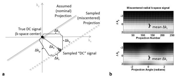
Gradient timing errors cause radial projections to be shifted away from the center of k-space. (a) The total shift Δke can be expressed in terms of parallel (Δkr) and perpendicular (Δkp) components, or in terms of the shift in the kx and ky directions. (b) The magnitude k-space signal from a spherical phantom exhibits characteristic signal fluctuations from projection to projection due to golden angle sampling (top trace), which are also clearly visualized when the signal is reordered by projection angle (bottom trace). The miscentered sampling causes an error in the sampling location of the peak (brightest) k-space signal, which can be described as a constant offset in the direction parallel to the projection, the mean Δkr, with an angle-dependent fluctuation.
It has been shown that image reconstruction using the actual trajectory instead of the nominal trajectory can reduce image artifacts (6–8). Trajectories are therefore commonly estimated or “measured” by performing separate phase calibration scans to determine gradient errors (4,6,9,10) or by using magnetic field probes (11). In the case of radial scanning, the trajectory can be determined retrospectively using axis-specific gradient calibration measurements and the known projection angles (4). In addition, the gradient calibration measurement can be fit to a model of gradient errors that can then be used to calibrate the scanner hardware itself (10) or to modify the pulse sequence by adding gradient pre-emphasis (3,4,12,13) to compensate for the timing errors.
While field probes perform imaging and trajectory measurement simultaneously, the more frequently used gradient calibration, trajectory measurement, and pulse sequence correction methods typically assume that the errors in the gradients and trajectory are consistent between the calibration measurement and imaging experiment. This assumption may not be accurate due to phenomena such as patient motion, gradient coupling, or other nonlinearities and temporal variations (14). In addition, this extra data acquisition and sequence correction is time-consuming and may be difficult to implement on certain MR systems. Finally, trajectory measurements cannot address the situation where the k-space signals are being used for other purposes. Although image reconstruction with a measured trajectory may be sufficient to reduce image artifacts, there is evidence that radial trajectory errors can cause errors in the sampled DC signal used for self-gating in small animals (5). Although these adverse effects on self-gating are not observed in 2D radial measurements in humans, trajectory errors may be relevant in applications of 3D radial scanning, where timing errors on three gradient axes cause more severe trajectory errors.
Recently, much work has been performed on methods which estimate radial sampling trajectory errors in a way which can be integrated into the image reconstruction process. One approach is to use signal consistency at the oversampled k-space center to determine the trajectory error and retrospectively shift projections to reduce artifacts in images reconstructed from miscentered radial data. The signal consistency can be assessed by comparing antiparallel or nearly anti-parallel projections in k-space (1,5,15,16) or properties of the reconstructed image (17). These methods recover centered radial k-space data by using the Fourier Shift Theorem and the estimated trajectory error. The majority of methods correct for the parallel component of the trajectory error, Δkr, without correcting the perpendicular component, Δkp (1,4,10,18). Although this perpendicular error may be small, correction could provide additional improvement in trajectory estimation and subsequent image reconstruction.
The purpose of this study is to simultaneously determine the trajectory error and obtain a re-centered k-space signal from data acquired with a miscentered radial trajectory. This goal is achieved by using the parallel imaging concept of GRAPPA operators (19,20) to iteratively shift each sampled miscentered projection in k-space until it is re-centered. The iterative algorithm yields both an estimate of the actual trajectory, which can be used to reconstruct an image from the acquired miscentered data, as well as a multichannel re-centered k-space signal. This method builds on our work presented at the 2012 annual meeting of the International Society of Magnetic Resonance in Medicine (ISMRM), in which the idea of iteratively applying GRAPPA operators to estimate radial k-space trajectories was introduced (21). The technique has the advantage of being completely retrospective and self-calibrating, requiring no additional hardware, calibration measurements, or pulse sequence modification, and is robust and stable. Other self-calibrated parallel imaging-based methods for retrospective trajectory and signal estimation have emerged since then (22–24). In particular, the method known as Self-Consistency for Iterative Trajectory Adjustment (SCITA) also uses the iterative application of GRAPPA operators to adjust the radial trajectory (22,23). The methods differ in the criterion used to determine the accuracy of the trajectory estimate: while SCITA relies on self-consistency between the projections, the method proposed here maximizes the root sum-of-squares DC signal of each individual projection, which can be advantageous in dynamic imaging applications.
THEORY
For most medical images, the k-space signal is highest in magnitude in the center of k-space, at k=0. Changes in the DC signal magnitude can result from changes in magnetization, contrast, or motion; otherwise the DC signal level should remain stable. However, when k-space is sampled with a miscentered radial trajectory and gridding is performed assuming a centered trajectory, the peak signal of the measured data may no longer be at k=0. This is illustrated in Figure 1b, where the magnitude k-space signal near the nominal (assumed) k=0 sampling point from a spherical phantom sampled with a golden-angle radial acquisition is visualized sorted by projection number (top trace) and by projection angle (bottom trace). The parallel component of the trajectory error is observed as the peak (brightest) k-space signal being shifted away from k=0 in the radial direction by a constant amount, labeled “mean Δkr,” with a projection-angle-dependent variation in the location of the peak signal. The parallel and perpendicular components of the trajectory error both result in a reduced signal level at the sample nominally acquired at k=0 in each miscentered k-space projection. The goal is to estimate the (unacquired) centered k-space signal from the miscentered radial data and to determine the location of the nominal trajectory relative to the miscentered k-space projections to estimate the trajectory error. This goal is achieved by shifting miscentered projections towards the center of k-space. The shift operation is performed using GRAPPA Operator Gridding (GROG) weights (19,20).
A GRAPPA operator is a set of weights, G, which can be applied to a multi-channel k-space source signal, SSrc, in order to generate a multi-channel target signal, STarg:
| [1] |
In GROG, the GRAPPA operator is applied to a single source point in order to generate a single target point. That is, if SSrc is an Nc×1 matrix representing a signal at a single point in k-space acquired with an Nc-channel receive array, then G will be an Nc×Nc matrix of weights which will generate the Nc×1 matrix representing the target signal STarg. Originally designed for the purpose of gridding samples from non-Cartesian trajectories, GROG weights can be used to shift individual acquired points in a multi-channel non-Cartesian k-space signal to obtain multi-channel signals at some non-sampled location in k-space. GROG base weights Gx and Gy are used to shift samples by the Nyquist sampling interval, Δk=1, in the kx and ky directions respectively:
| [2] |
A scaled version of the base weights, GxΔx and GyΔy, can be applied to shift samples by smaller intervals, Δx and Δy (19). The scaled weights can be computed from the eigenvalue decomposition of the base weight matrix, G, as
| [3] |
where E is the matrix of eigenvectors of G, and VΔ is a diagonal matrix of eigenvalues of G raised to the Δth power. The multi-channel target (shifted) signal is obtained by multiplying the multi-channel source (acquired) signal by the scaled weights:
| [4] |
The base weights, Gx and Gy, can be calibrated from a multi-channel signal sampled with a known, regularly spaced trajectory. While the example shown here is for base weights calculated for a Δk=1 shift, it is also possible to calculate base weights for other smaller shifts; for instance, in the case of read oversampling, the base weights are often for shifts of Δk=0.5. It is helpful to note that the angle and spacing of the sampled points in each miscentered projection will be correct along the majority of the radial read-out even in the presence of gradient delays because the gradient amplitude is generally correct in the steady state (14,25). The consistency in projection angle and sample spacing allows the GROG base weights to be self-calibrated from the miscentered radially sampled data (20).
To estimate the trajectory error, GROG weights can be applied to shift each projection by a small amount, and the DC signal can be estimated from the shifted projection. A search algorithm can be used to find the applied shift which increases the DC signal estimate. Repeating this process will shift each projection until the DC signal estimate is maximized. At this point, the projection presumably passes through the center of k-space and the signal along the projection is presumably re-centered. The k-space shift corresponding to the cumulative shift from iteratively applying GROG can be used to estimate the trajectory traversed at each projection angle. The estimated trajectory can be used to improve image reconstruction.
METHODS
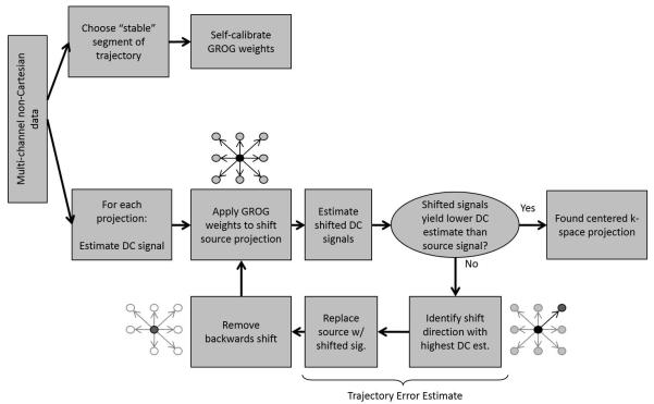
An overview of the proposed self-calibrated signal correction and radial trajectory estimation algorithm is illustrated in Figure 2a. The method includes a pre-processing step to correct the mean Δkr (Figure 2b), followed by the iterative application of GROG weights (Figure 3) to refine the trajectory estimate and recover an estimated re-centered signal.
FIGURE 2.
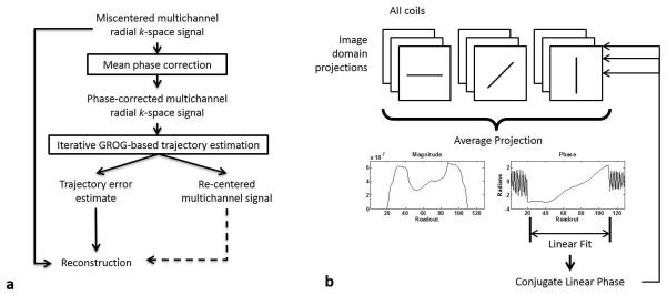
(a) Workflow for GROG-based trajectory estimation and signal correction for radial trajectories. Multi-channel radial data is first subject to a phase correction (b) to estimate and remove the mean parallel component of the k-space trajectory error. GROG is then iteratively applied to the phase-corrected signal to determine the residual trajectory error from each recentered projection. The trajectory estimate is used to reconstruct a corrected image from the acquired miscentered signal.
FIGURE 3.
Iterative GROG-based trajectory correction algorithm. For each miscentered radial projection, estimates of the centered projection and the trajectory error are returned.
Mean Phase Correction
It has previously been shown (4) that the parallel and perpendicular components of the trajectory error, Δkr and Δkp, are functions of the projection angle and the relative delay between the data acquisition window and gradient timing. In the axial scan plane, these errors can be calculated as
| [5a] |
| [5b] |
where Gread is the strength of the radial readout gradient (i.e. Gread = (Gx2 + Gy2)1/2), γ is the proton gyromagnetic ratio, and tx and ty are the time delays of the centers of the x- and y-gradient echoes, respectively, relative to the center of the data acquisition window. When tx=ty then Δkp =0 and Δkr is constant for all projection angles. The Δkr can be observed directly from the shift in the peak signal location in each acquired radial spoke. The mean Δkr across all projections represents the portion of the parallel trajectory error which is due to the gradient timing errors and is not angle-dependent, and can be estimated so long as projections are acquired on the 0-π or 0-2π interval.
The mean Δkr is removed using a process similar to those previously described (26,27) and illustrated in Figure 2b. This constant offset in the k-space signal corresponds to a phase across the corresponding image-domain projection. In multi-channel data, this phase is in addition to the relative phase from each coil element. To correct the mean Δkr from all projections, a conjugate mean linear phase is applied to all image domain projections. The mean phase is computed by performing a one-dimensional Fourier Transform along each k-space projection, followed by taking the mean image domain signal across all projection angles and all channels. The unwrapped phase from this mean image domain projection is computed, and a line is fit over the region where the object yields signal (28). The mean linear phase extrapolated over the whole field of view, ΔΦ, is then complex conjugated to yield an estimated linear phase correction, which is then applied to all image projections in all channels. Finally, the inverse Fourier Transform is performed, resulting in a constant shift in the k-space signal along the read-out direction of all k-space projections:
| [6] |
Initial estimates of the kx and ky components of the trajectory error are computed from the mean parallel trajectory error for each projection angle θ as
| [7a] |
| [7b] |
We refer to this pre-processed k-space signal as the “phase-corrected” signal and the corresponding trajectory estimate as the “phase-estimated” trajectory in the remainder of the manuscript.
GROG-Based Iterative Search
When Δkp =0 the mean phase correction stage is sufficient for estimating the trajectory error. However when a perpendicular component to the trajectory error exists, additional refinement in the trajectory estimate can be made by the iterative application of GROG. Figure 3 describes the GROG-based iterative search strategy. GROG base weights are self-calibrated (20) from the central half of the read-out points from all collected radial projections after phase correction. This portion of the projection is used as the gradients are assumed to be in steady state and the signal level is relatively high. Because the data is oversampled in the read-out direction, the base weights correspond to a shift of Δk=0.5 in the kx and ky directions. From this point onwards, the algorithm operates on a projection-by-projection basis.
In the first step, an initial estimate of the DC signal must be made. This can be achieved in many ways. In this work, the signal at the center of k-space is initially estimated by taking the root sum-of-squares (SOS) combination (29) of the miscentered multi-channel k-space signal at the point along each projection which is nominally sampled at k=0. The GROG weights are then scaled and applied to shift the whole projection by a fraction of the k-space sampling interval, Δk, in all combinations of the positive and negative kx and ky directions. That is, the projections are shifted according to the pairs (+Δkx,+ Δky), (+Δkx,0), (+Δkx,− Δky), and so on. In this implementation, Δk = 0.01Δk was used to obtain an accurate trajectory estimate; larger shift intervals could reduce the number of required iterations at the cost of accuracy in the estimated trajectory error and DC signal. It should be noted that it is not necessary to shift the whole projection; using only the centermost read-out points is also possible. However, applying the weights only to a single sample, such as the signal nominally sampled at k=0 or to the sample with the highest DC estimate along the miscentered projection, should be avoided. This is because the iterative application of GROG gradually shifts the signals to intermediate unsampled locations, and the peak signal may appear at a different point along the read-out as the projection is shifted.
If no shift results in a higher DC estimate than the current estimated value, then it is assumed that the projection is re-centered and the algorithm is terminated. Otherwise, the shift resulting in the highest DC estimate, subject to convexity constraints on the increase of the DC estimate to enforce convergence, is chosen as a step towards the center of k-space. In each iteration, the additional Δkx and Δky shift is recorded, forming a path between the sampling location of the miscentered signal and the estimated center of k-space. In order to avoid retracing steps along this path, the backwards shift is removed for the next iteration. That is, if the current iteration takes a step in the (+Δkx, +Δky) direction, the (−Δkx, −Δky) shift option is removed in the following iteration. To avoid error accumulation due to round-off errors, the cumulative GROG shift is always applied to the input (phase-corrected) projection in each iteration.
As indicated in Figure 3, the termination of the search algorithm yields two outputs for each projection. The first is the “GROG-estimated” trajectory error in the kx and ky directions found through the cumulative GROG shift, Δkxg and Δkyg. The second output is the estimated recentered radial k-space projection, referred to as the “GROG-corrected” signal in the remainder of the text.
Trajectory Error Estimation
The total trajectory error estimate is obtained by subtracting the shift estimated in the GROG-based algorithm from the error estimated from the mean phase correction: Δkx = Δkxp - Δkxg and Δky = Δkyp - Δkyg. The parallel component of the trajectory error, which is observed as a shift along the projection in k-space, is computed as Δkr (θ) = Δkx·cos θ + Δky·sin θ (Equation 2 in Reference 4).
Simulation
As proof of concept, a simulation was performed with MATLAB software (The Mathworks, Natick, Massachusetts). Coil sensitivity profiles for an 8-channel one-ring array were calculated over an axial slice from Biot-Savart equations. A 128×128 Shepp-Logan phantom was generated as the object. The multichannel golden-angle radial k-space data (144 projections, 256 readout points, 128×128 base matrix) were obtained through degridding using the nonuniform FFT (30) implementation in the Fessler image reconstruction toolbox (available online at http://web.eecs.umich.edu/~fessler/code/). A miscentered radial signal was produced by degridding on a trajectory with induced errors Δkx(θ) = 1.2Δk·cos θ and Δky(θ) = 1.4Δk·sin θ. The trajectory estimation algorithm was then applied to the simulated miscentered data, as described previously in the Methods section.
Imaging Experiments
Images were acquired on a 1.5T Avanto clinical imaging system (Siemens Healthcare, Erlangen, Germany). Validation studies were performed on a spherical phantom. In-vivo experiments were performed under institutional regulatory approval on healthy volunteers who had given informed consent. In all experiments, data were acquired with a 2D golden-angle radial TrueFISP sequence. No modifications were applied to the pulse sequence to compensate for gradient errors in these acquisitions. Phantom and head measurements were made with a 12-element head coil in the axial plane. Breath-held cardiac measurements were made with a 15-element body array coil in a double-oblique short-axis view. All imaging measurement parameters are listed in Supporting Table S1.
Raw multi-channel data were exported from the scanner with read-out oversampling factor 2 and processed offline using MATLAB. Trajectory and DC signal estimation were performed as described previously in the Methods section.
Analysis
To visually inspect the effects of the phase correction and iterative GROG correction, the root sum-of-squares (SOS) combination (29), which removes any effects arising from the relative phase between elements in the coil array, was applied to multi-channel k-space signals and the sampling location of the peak signal was observed. Accurate correction is expected to shift the peak signal along each projection towards k=0.
The SOS DC signal along each projection (assumed to be sampled at k=0) was computed from the miscentered radial signal, phase-corrected signal, and GROG-corrected signal. Accurate trajectory correction is expected to result in temporally smooth SOS DC signals. In the case of cardiac imaging, the SOS DC signal was also filtered with a 128-point FIR band pass filter with the pass band frequency range of 0.5-3 Hz to isolate signal changes due to cardiac motion. This filtered DC signal is later used as a navigator for self-gated CINE reconstruction (2).
Multi-channel images were reconstructed using the regridding operations in the Fessler image reconstruction toolbox from the miscentered signal with the nominal trajectory, phase-estimated trajectory, and GROG-estimated trajectory. For the simulation experiment, a reference reconstruction with the simulated miscentered data and the known miscentered trajectory was also generated. In all reconstructed images displayed in this manuscript, single-channel images are SOS combined. For the breath-held cardiac acquisitions, the filtered SOS corrected DC navigator was used for retrospective self-gating (2) with 15 CINE frames. Briefly, fiducial points in the troughs of the navigator signal were automatically identified, and all projections between two consecutive fiducial points were binned into one of 15 frames. Projections in each bin were gathered across cardiac cycles. In the case where multiple projections at the same angle were binned together, the projection signals were averaged. From the projections in each bin, an image was reconstructed to form one frame in the CINE series. Representative frames from systole and diastole, identified by visual inspection of the CINE series, are presented.
To assess the improvement in image reconstruction with the estimated trajectory compared to reconstruction with the nominal trajectory, the root-mean-square error between each reconstruction and the reference image was calculated in the simulation experiment. In the phantom and head experiments, the background signal level was quantified instead. The total background signal level was calculated by masking out the object or anatomy in the SOS combined image, and normalizing the sum squared background signal by the sum squared total image signal.
Finally, to check the assumption that the signal maximized at k=0 and smooth at the center of k-space, mesh plots of the k-space signal gridded with the GROG-based trajectory estimate are generated for the Shepp-Logan phantom, spherical phantom, head measurement, and short-axis cardiac measurement in systole.
RESULTS
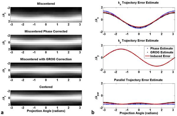
Figure 4 contains the results of the phantom simulation. Examination of the SOS combination of multi-channel radial k-space data reveals the effects of the phase correction and the iterative application of GROG. The golden angle radial signal is observed to be miscentered, since the peak signal is not consistently sampled at kr=0. Reordering the miscentered data by projection angle (Figure 4a, first row) reveals the additional projection-angle dependency of the trajectory error. By comparison, the peak signal is sampled consistently at kr=0 in the centered reference signal which has no trajectory error (Figure 4a, fourth row). Correcting the mean phase from all projection angles results in the peak SOS signal being shifted by −1.41Δkr along each radial projection (Figure 4a, second row). The additional iterative application of GROG removed the remaining angle-dependent fluctuations in the peak signal location, resulting in the re-centered signal peak being located at the radial sample nominally at kr=0 (Figure 4a, third row). The GROG-corrected k-space signal is in good agreement with the centered reference signal (Figure 4a, fourth row).
FIGURE 4.
Evaluation of trajectory error estimation in simulation with a 2D golden angle radial trajectory. The SOS k-space signal ordered by projection angle (panel a, first row) reveals an angle-dependent variation in the trajectory error with a mean offset in the location of the peak signal along each projection. The mean parallel shift is removed by applying a phase correction (panel a, second row). The additional iterative application of GROG re-centers the miscentered signal such that the peak signal appears consistently at kr=0 (panel a, third row). The k-space signal of a simulated measurement with a centered trajectory is included for comparison (panel a, fourth row). The estimated trajectory error in the kx and ky direction (panel b, first and second rows, respectively) also exhibit an angle dependency. Phase correction followed by iterative GROG (black traces) yields a more accurate trajectory estimate than phase correction alone (blue traces) when compared to the known induced error on each axis (red line). The parallel component of the trajectory error (panel b, third row) exhibits an angle-dependent variation which closely matches the error in the peak signal sampling location observed in the miscentered acquisition (panel a, first row).
The trajectory error estimated in the kx and ky directions, as determined from phase correction and iterative application of GROG, is plotted in Figure 4b. In the axial scan plane, a sine/cosine-type variation in the estimated error with respect to projection angle was observed. The component of the trajectory error estimated from phase correction (blue) using Equations 6-7 resembles the induced error (red) but is further corrected by the additional iterative application of GROG (black). The final GROG-estimated error has magnitude 1.1Δk on the kx-axis (Figure 4b, first row) and 1.4Δk on the ky-axis (Figure 4b, second row). The residual trajectory error after the iterative GROG stage is −0.08Δk in the kx direction and −0.02Δk in the ky direction. Note that the component of these errors which lies parallel to the read-out direction, Δkr, (Figure 4b, third row) exhibits an offset and angle-dependent variation which closely matches the error in the peak signal sampling location observed in the simulated miscentered acquisition (Figure 4a, first row).
Similar results in trajectory error estimation and signal re-centering were observed in imaging experiments. The SOS k-space signals ordered by projection angle show miscentered signals with a mean offset and angle-dependent fluctuation in the spherical phantom (Figure 5a, top row), head (Figure 5b, top row), and heart (Figure 5c, top row). Variations in the peak signal level observed in the head scan are due to the signal not reaching steady state and are further addressed in the remainder of the text. A clear angle dependence in the peak signal location can be observed in the phantom and head, which were scanned in the axial plane, while a more complicated angle dependence is observed in the cardiac cine images due to the double-oblique scan plane. At projection angles between +1 and −1 radian, the error in the location of the peak signal appears to be at least 1Δk, and at angles near ±π/2 radians the location of the peak signal changes dramatically over a small range of projection angles.
FIGURE 5.
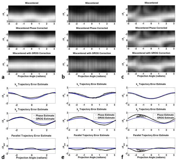
Evaluation of trajectory estimation in an axial view of a spherical phantom (a, d), head (b, e), and breath-held cardiac (c, f) experiments.
Mean phase correction removes a constant shift of 0.85Δkr for the spherical phantom (Figure 5a, second row), 0.63Δkr for the head (Figure 5b, second row), and 0.75Δkr in the cardiac cine images (Figure 5c, second row). The subsequent iterative application of GROG reduces the residual angle-dependent fluctuation in the peak signal location, effectively recentering the k-space signal in the phantom and head experiments (third rows of Figures 5a and 5b, respectively). The GROG search stage also shifts the peak signal sampling location towards k=0 in the heart scan, but some residual errors remain (Figure 5c, third row).
After additional refinement using the iterative application of GROG, the trajectory error magnitude estimated is 0.65Δkx and 1.12Δky in the phantom, 0.77Δkx and 1.11Δky in the head, and 0.75Δkx and 1.13Δky in the heart (first and second rows of Figures 5d, 5e, and 5f, respectively). The computed parallel components of the trajectory error in the phantom and head experiments closely match the observed shift in the peak signal locations (Figures 5d, and 5e, third rows). The parallel component in the cardiac cine images estimates the trajectory error accurately for projection angles near ±π and underestimates the trajectory error for angles near 0 radians (Figure 5f, third row). The consistency of the estimated trajectory error magnitudes and angle dependency observed in the axial phantom and head experiments, despite the signal not reaching steady state in the latter case, indicates that the trajectory estimation method is robust to changes in the signal level.
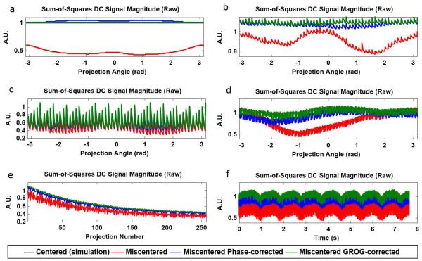
In addition to the estimated trajectory error, the proposed algorithm also returns the estimated signal along each re-centered projection. The raw DC signal of a static object is expected to be constant when sampled with a centered trajectory and the magnetization is in steady state. The DC signal is expected to decrease with severity of the parallel or perpendicular trajectory error. The projection angle dependence of the trajectory error results in projection angle dependence of the DC signal value. The raw DC signal in the simulated miscentered phantom shows large variations with projection angle (Figure 6a). The DC variations in the simulated miscentered phantom data are larger than the variations in the miscentered DC signal in the phantom and in vivo experiments (Figures 6b,c,d), commensurate with the severity of the estimated trajectory error.
FIGURE 6.
DC signal magnitude in simulation (a), spherical phantom experiment (b), head experiment (c,e), and breath-held cardiac experiment (d,f). Measurement with a miscentered trajectory causes reduced signal level and large signal fluctuations (red traces). Trajectory estimation based on phase correction alone moderately increases signal level and reduces but does not eliminate signal fluctuations (blue traces). Trajectory estimation with the additional iterative application of GROG further increases signal level and reduces signal fluctuations (green traces).
Phase correction of the simulated phantom data alone increases the DC signal level but does not completely remove signal variations. Further correction with the proposed GROG-based algorithm yields a constant re-centered signal with signal level matching that of the simulated centered signal. Similar results are observed in the spherical phantom measurement (Figure 6b), with large variations in the DC signal from the miscentered acquisition, reduced variation in the phase-corrected signal, and nearly negligible variation in the GROG-corrected signal estimate. In the head and breath-held cardiac experiments, the phase-correction and GROG-based correction reduce angle-dependent variation in the DC signal (Figures 6c and 6d). The raw DC signal from the miscentered trajectory decays with time in the head experiment due to not being in steady state, and the application of phase correction and iterative GROG preserves the change in the signal as the magnetization approaches steady state (Figure 6e). Similarly in the breath-held cardiac experiment (Figure 6f), the baseline DC signal level is reduced by the miscentered trajectory. Correction with the proposed method both increases temporal smoothness and the signal level without distorting the morphology of the underlying cardiac motion signal.
Figure 7 shows simulation images reconstructed with the nominal trajectory, phase-estimated trajectory, and GROG-estimated trajectory. The reference reconstruction, with miscentered data reconstructed with the known miscentered trajectory, exhibits no apparent artifacts. Images reconstructed using the simulated miscentered data and the nominal trajectory exhibit characteristic hyperintensity near the center of the object, signal voids at the object edges, and strong streak artifacts resulting in a root-mean-square error (RMSE) of 0.42 relative to the reference image. Reconstruction with the phase-estimated trajectory improves the contrast and reduces the streaks, improving the RMSE to 0.07. Reconstruction with the GROG-estimated trajectory removes nearly all residual artifacts in simulation, resulting in RMSE of 0.01. Difference images with enhanced contrast and brightness demonstrate the reduction of streak artifacts and noise in the object and background compared to the reconstructions assuming the nominal trajectory.
FIGURE 7.
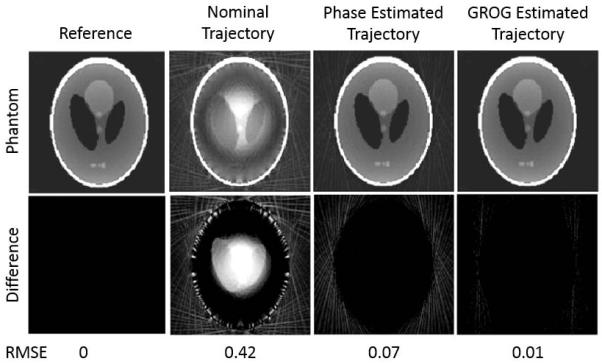
Image reconstruction of a simulated miscentered radial acquisition with various trajectories. The reference image depicts miscentered radial data reconstructed with the known miscentered trajectory. Reconstruction with the nominal trajectory results in severe contrast distortion within the object and strong streak artifacts. Use of the trajectory estimated from the proposed iterative GROG algorithm restores the true image contrast and removes residual artifacts beyond the improvement observed from reconstruction with the trajectory estimated in the pre-processing phase correction step. Difference images in the second row (enhanced for clarity) illustrate residual artifacts. Quantified root mean square error relative to the reference reconstruction is printed beneath the images.
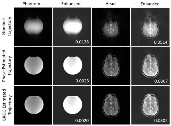
Figure 8 shows acquired data from the phantom and head scans reconstructed with the nominal trajectory, phase-estimated trajectory, and GROG-estimated trajectory. Characteristic hyperintensity in the object center and signal voids at the object edges are observed in both reconstructions with the nominal trajectory. Enhanced image contrast and brightness demonstrate the reduction of streak artifacts and noise in the background compared to the reconstructions assuming the nominal trajectory. Reconstructions with the phase-estimated trajectory show improvement in contrast, but residual artifacts. These are especially apparent in the head image, with signal voids and streaks remaining near the frontal regions of the brain. Reconstruction with the GROG-estimated trajectory further improves uniform contrast and reduces background artifacts. Relative background signal is most reduced when the GROG-based trajectory estimate is used.
FIGURE 8.
Miscentered radial data acquired in a spherical phantom and the head show improved contrast and reduction in streak artifacts when reconstructed with the GROG-estimated trajectory compared to reconstruction using the phase-estimated trajectory or the nominal trajectory. Background signal power, reported in the insets, is reduced when the GROG-based trajectory estimate is used for reconstruction.
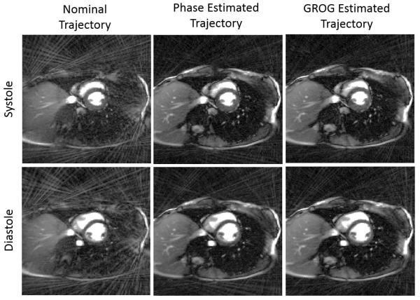
Retrospective self-gating with the filtered DC signals yielded cardiac CINE images with 15 frames per cardiac cycle and 113 unique projection angles per frame. Representative images from the systolic and diastolic phases are presented in Figure 9. Images reconstructed with the nominal trajectory exhibit signal voids and strong streak artifacts in the chest wall and lungs. Reconstruction with the phase-estimated trajectory reduces the streak artifacts within the thorax and outside the anatomy, and improves visualization of the left ventricular free wall, especially in the diastolic phase. Only minor improvements in contrast and artifact reduction are observed when images are reconstructed with the GROG-estimated trajectory compared to the phase-estimated trajectory, consistent with the minor re-centering of the k-space signal observed in Figure 5c.
FIGURE 9.
Representative cardiac CINE images from systole and diastole. Reconstruction with the nominal trajectory results in signal voids and strong streak artifacts (left column) while reconstruction with the phase-estimated trajectory (center column) and GROG-estimated trajectory (right column) restores contrast of internal structures and reduces signal voids. Image contrast and brightness have been enhanced to better visualize residual artifacts.
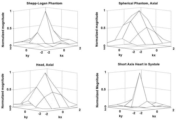
Surface renderings of the signal at center of k-space after gridding with the GROG-estimated trajectory for the Shepp-Logan phantom, spherical phantom, head, and short-axis cardiac images, are shown in Figure 10. All surfaces show peak signal at k=0 and a reduction in signal by 20-70% within 1Δk.
FIGURE 10.
Mesh plots of the signal at the center of k-space for the objects and anatomies shown in Figures 7, 8, and 9.
DISCUSSION
The proposed self-calibrated iterative GROG-based technique can be used to robustly estimate miscentered radial trajectories. Reconstruction with the resulting trajectory estimate was demonstrated to improve contrast and reduce artifact. The proposed trajectory error estimation method works for different types of anatomy and in different scan plane orientations. Unlike traditional trajectory measurement techniques, which first require calibration on each gradient axis followed by calculation of the trajectory error from the known projection angles, the proposed method is retrospective and self-calibrating. No gradient-axis-specific measurement or calibration is necessary in this technique, making it easier to implement, especially in experimental setups where these types of calibration measurements may be difficult to make. Finally, the proposed technique estimates the trajectory of each projection independently and does not rely on any self-consistency metric, making it well-suited for dynamic and quantitative imaging applications.
Although previous techniques have been presented for correcting radial trajectory errors, they exclusively correct the mean parallel component of the trajectory error (4,10,18). For the most accurate estimate of the trajectory error, however, the residual parallel and perpendicular error must also be considered. In the proposed method, the mean Δkr component of the sampling error is corrected in the pre-processing step and used as a preliminary trajectory estimate. Accounting for the mean Δkr trajectory error improved image contrast and reduced artifacts. While this level of correction may be sufficient in some applications, the simulations and experiments presented in this study demonstrate that residual artifacts and signal voids in the reconstructed images and fluctuations in the DC signal remain. In the proposed method, both the parallel and perpendicular trajectory errors are corrected by the additional iterative GROG-based search strategy, which was shown in simulation to accurately detect trajectory error. Reconstruction with the refined, GROG-estimated trajectory removed residual contrast errors, artifacts, and signal fluctuations in phantom and in-vivo experiments.
The fundamental assumption in the proposed trajectory estimation technique is that the k-space signal is maximal at the center of k-space and that it is convex. The mesh plots of the signal at the center of k-space confirm this assumption. Furthermore, the k-space signals are sufficiently smooth within 0.2Δk of k=0 that errors within this central region do not cause severe image artifacts. While the global k-space signal is non-convex, the limited region near the center of k-space has purely convex signal characteristics under certain conditions outlined later in this section. The pre-processing step of mean phase correction is therefore important because it limits the trajectory error to be within this smooth, convex central region of k-space, such that the trajectory error can be further refined by the iterative application of GROG. Under these conditions, the algorithm will converge to the globally optimal result.
Recent studies have documented distortion in the cardiac DC-self-gating signals of small animals due to trajectory errors, and the restoration of the gating signals when trajectory correction is applied (5). However, trajectory error and its correction did not affect the performance of self-gating in our 2D cardiac experiments on human subjects. These distortions and their correction are not observable because the frequency of radial angle sampling (which causes the distortion in small animal imaging) is comparable to the frequency of cardiac motion, and its higher harmonics are filtered out in the process of isolating the cardiac self-gating signal (2).
The proposed trajectory estimation technique performs well for scans in the axial plane, as demonstrated by experiments performed in the phantom and head. However some limitations are observed in the cardiac experiment (Figure 5c). While the proposed algorithm is able to re-center the signal at some angles, at others the parallel component of the trajectory error is underestimated and the signal is not completely re-centered. The corrected signal appears to remain miscentered by approximately 0.5Δk even after the iterative GROG algorithm is applied. The peak signal location changes abruptly at projection angles of approximately ±π/2, indicating that the cause of the residual error is primarily in the kx direction. These errors, which were not observed in the phantom and head experiments, could be due to inherent miscentering in the k-space signal because in the presence of substantial fat which is out of phase with the water signal, off-resonance can cause the peak k-space signal to not be located at k=0. Linear shim errors can also cause the peak k-space signal to be located at k≠0. The off-resonance effect on the peak k-space signal location may be alleviated by manually adjusting the center frequency (31). Shim errors could be characterized and corrected by performing a pre-scan measurement in the kx and ky directions with a short echo time and slow gradient timing such that any trajectory errors due to timing are negligible. The shimming or trajectory could then be adjusted to re-center the peak k-space signal. Another explanation for this error is that the peak k-space signal shifts over time due to motion. However it should be noted that offset or shifting k-space signals will pose a problem to all retrospective trajectory estimation techniques which model gradient timing errors without taking additional phase errors into account.
The shift range over which GROG can be applied accurately may be limited when certain requirements are not met. First, calibration of the weights must be performed with a sufficient number of projections. The GROG weight calibration does not require fully-sampled data: weights can be calibrated from as few as 2 projections, and more accurate weights are obtained when more projections are used (20). In the presented in-vivo experiments, all available projections were used for calibration. Another requirement is that the coil array provides sufficient variation in sensitivity profiles within the scan plane. When the sensitivity variation is insufficient, the shift range over which GROG is accurate may be small. While this limitation is not problematic for the purpose of gridding where the largest shift necessary is 0.5Δk, it poses a limitation in this trajectory estimation application such that large trajectory errors may not be accurately estimated by GROG alone. Therefore pre-processing with mean phase correction is an important step in reducing the range of error left for GROG to correct. If needed, GROG weight calibration could be improved with more coils, a different coil arrangement, or some retrospective manipulation of the coil sensitivities (32).
The calculation of GROG weights is a single-point-to-single-point estimate. Hence the use of GROG in any application will add noise to the signal. The added noise may be negligible when GROG is applied to achieve only a small shift within the accuracy limits for the particular coil configuration. However the iterative application of GROG weights, especially when they are poorly calibrated, may add significant levels of noise. For this reason, constraints on the estimated magnitude of the DC signal were implemented in the search algorithm. In experiments in which GROG weights are poorly calibrated and applied to correct severe trajectory errors, the noise accumulation in the re-centered k-space signal may result in a misestimated trajectory error or render the re-centered signal estimate unusable for image reconstruction. In systems with less severe trajectory errors which can be corrected with small GROG shifts, or where more suitable coil arrangements and more accurate GROG weight calibrations are available, the noise enhancement may be reduced and the re-centered acquired signal may still be suitable for use in image reconstruction. This may be the case if this technique were used in addition to gradient hardware adjustments or pulse sequence corrections which are already in place.
The proposed GROG-based trajectory error estimation approach makes no effort to discern which component of the trajectory error is due to eddy currents, gradient timing delays, gradient coupling, clock shift errors, or other effects. In particular, eddy currents due to golden angle sampling may be more severe in the double oblique scan plane or in the presence of substantial off-resonance (33), potentially contributing to residual streak artifact observed in the GROG-corrected cardiac cine images. Gradient errors have been shown to drift with acquisition time and temperature (14) and further modeling is needed to relate the trajectory estimated in this approach to actual errors in the physical gradient performance.
A recently published technique called Self-Consistency for Iterative Trajectory Adjustment (SCITA) also uses an iterative self-calibrated GROG approach to trajectory estimation, and also yields a re-centered radial k-space signal and trajectory estimate (22,23). SCITA provides two possible alternatives to the method presented in this work. It performs a rough trajectory assessment at a large GROG step size of 0.5Δk, then iteratively refines the trajectory estimate by gradually reducing the GROG step size to 0.01Δk. The method proposed in this work achieves the same effect but with possibly fewer computations by first performing mean phase correction to remove large trajectory errors and then applying iterative GROG correction with a small stepsize of 0.01Δk to refine the trajectory estimate and correct residual errors. SCITA also differs in its assessment of trajectory accuracy: instead of maximizing the k-space signal at k=0 along each projection, it takes a data consistency approach which minimizes the difference between the shifted k-space projection signal and an averaged k-space signal which takes into account all projections. The data consistency approach was shown to work robustly in situations where the contrast or object itself is not changing with time. However since this averaged data may be corrupted by motion and other errors, this may lead to lower quality results. This is especially true in dynamic imaging applications such as CINE or contrast-enhanced imaging where it may be important to assess trajectories on a projection-by-projection basis: comparing the k-space projection signal at individual time points to a time-averaged image signal could cause errors in the trajectory estimation step due to changing contrast or underlying physiologic signal variation.
The method detailed in this study could be improved in several other ways. In this work, GROG weights are self-calibrated using the central half of each projection. Partial-echo calibration, such as from ultrashort echo time datasets, may also be possible but has not yet been investigated. In this study, the center of k-space is evaluated based on the peak SOS k-space signal. However other definitions and coil combination methods can be used and this choice may affect convergence of the iterative trajectory estimation algorithm. The number of iterations in the GROG-based trajectory correction stage could be reduced if the observed parallel error is modeled directly as a sinusoidal function of projection angle instead of as a constant shift as we have modeled in the mean phase correction stage, although this may require some form of interpolation in the readout direction to be accurate. The step size used in each iterative application of the GROG weights may also be further optimized to balance the tradeoffs between accuracy in trajectory estimation, noise enhancement, and computations per iteration. The computation time of the proposed trajectory estimation method depends on the trajectory error of each projection relative to the mean phase correction trajectory estimate, the number of projections, and the step size. For a single projection and a step size of 0.01Δk, each iteration of the application of GROG and the decision of which trajectory shift direction to use takes 0.02s on an Intel Xeon 2.6GHz processor. For 256 projections, the overall computation time for the trajectory estimate (including the mean phase correction pre-processing stage) is 23s. The method presented in this study uses a derivative-free optimization method to find the location of the peak k-space signal. One alternative to the iterative search strategy is to perform a brute-force search of all possible projection shifts within a small region near the center of k-space; although this strategy is computationally impractical, it could address cases where the peak k-space signal is not located at k=0 for example. Several more efficient optimization algorithms could be employed to determine the location of the peak k-space signal, but these comparisons are left to future studies. The number of required computations may also be reduced by applying GROG only to the central part of each projection, provided this segment captures the peak signal and the nominal k=0 sample, instead of all points along the projection in the search algorithm.
CONCLUSION
We have presented a technique which simultaneously estimates the traversed non-Cartesian trajectory from data acquired along miscentered 2D radial trajectories, re-centers the k-space signal, increases the DC signal level and reduces projection-to-projection signal variations. The technique is completely self-calibrating and retrospective, and requires no additional hardware, extra data acquisition, or modifications to the pulse sequence. This parallel-imaging-based procedure provides a re-centered multi-channel radial k-space signal for later use in other accelerated imaging applications. Each projection is processed individually, thereby preserving dynamic information related to changes in contrast, relaxation, or motion which often prove useful for dynamic imaging and quantitative imaging applications.
Supplementary Material
ACKNOWLEDGEMENTS
The authors wish to acknowledge Dr. Philipp Ehses for providing the radial TrueFISP sequence, Michael Völker and Daniel Neumann for helpful discussions on improving the method, and MR Bavaria for assistance in collecting data. This research was funded by the Whitaker International Program administered by the Institute of International Education (IIE), Siemens Healthcare, and NIH grants T32EB007509, 1RO1HL094557, and R00EB011527. This work is solely the responsibility of the authors and does not necessarily represent the official views of the NIH.
REFERENCES
- 1.Rasche V, de Boer RW, Holz D, Proksa R. Continuous radial data acquisition for dynamic MRI. Magn. Reson. Med. 1995;34(5):754–61. doi: 10.1002/mrm.1910340515. [DOI] [PubMed] [Google Scholar]
- 2.Larson AC, White RD, Laub G, McVeigh ER, Li D, Simonetti OP. Self-gated cardiac cine MRI. Magn. Reson. Med. 2004;51(1):93–102. doi: 10.1002/mrm.10664. [DOI] [PMC free article] [PubMed] [Google Scholar]
- 3.Aldefeld B, Börnert P. Effects of Gradient Anisotropy in MRI. Magn. Reson. Med. 1998;39(4):606–614. doi: 10.1002/mrm.1910390414. [DOI] [PubMed] [Google Scholar]
- 4.Peters DC, Derbyshire JA, McVeigh ER. Centering the projection reconstruction trajectory: reducing gradient delay errors. Magn. Reson. Med. 2003;50(1):1–6. doi: 10.1002/mrm.10501. [DOI] [PMC free article] [PubMed] [Google Scholar]
- 5.Buonincontri G, Methner C, Krieg T, Carpenter TA, Sawiak SJ. Trajectory correction for free-breathing radial cine MRI. Magn. Reson. Imaging. 2014;32(7):961–964. doi: 10.1016/j.mri.2014.04.006. [DOI] [PubMed] [Google Scholar]
- 6.Duyn JH, Yang Y, Frank JA, van der Veen JW. Simple correction method for k-space trajectory deviations in MRI. J. Magn. Reson. 1998;132:150–153. doi: 10.1006/jmre.1998.1396. [DOI] [PubMed] [Google Scholar]
- 7.Dale BM, Duerk JL. The use of measured k-space trajectory for reconstruction of radial MRI data. Proceedings of the 10th Annual Meeting of ISMRM; Honolulu, USA.. 2002. p. 2334. [Google Scholar]
- 8.Lu A, Brodsky E, Grist TM, Block WF. Rapid fat-suppressed isotropic steady-state free precession imaging using true 3D multiple-half-echo projection reconstruction. Magn. Reson. Med. 2005;53(3):692–699. doi: 10.1002/mrm.20389. [DOI] [PubMed] [Google Scholar]
- 9.Zhang Y, Hetherington HP, Stokely EM, Mason GF, Twieg DB. A novel k-space trajectory measurement technique. Magn. Reson. Med. 1998;39(6):999–1004. doi: 10.1002/mrm.1910390618. [DOI] [PubMed] [Google Scholar]
- 10.Speier P, Trautwein F. Robust radial imaging with predetermined isotropoic gradient delay correction. Proceedings of the 14th Annual Meeting of ISMRM; Seattle, USA.. 2006. p. 2379. [Google Scholar]
- 11.De Zanche N, Barmet C, Nordmeyer-Massner JA, Pruessmann KP. NMR probes for measuring magnetic fields and field dynamics in MR systems. Magn. Reson. Med. 2008;60(1):176–186. doi: 10.1002/mrm.21624. [DOI] [PubMed] [Google Scholar]
- 12.Davies NP, Jezzard P. Calibration of gradient propagation delays for accurate two-dimensional radiofrequency pulses. Magn. Reson. Med. 2005;53(1):231–236. doi: 10.1002/mrm.20308. [DOI] [PubMed] [Google Scholar]
- 13.Bowen CV, Gati JS, Menon RS. Robust prescan calibration for multiple spin-echo sequences: application to FSE and b-SSFP. Magn. Reson. Imaging. 2006;24(7):857–867. doi: 10.1016/j.mri.2006.04.008. [DOI] [PubMed] [Google Scholar]
- 14.Brodsky EK, Samsonov AA, Block WF. Characterizing and correcting gradient errors in non-cartesian imaging: Are gradient errors linear time-invariant (LTI)? Magn. Reson. Med. 2009;62(6):1466–1476. doi: 10.1002/mrm.22100. [DOI] [PMC free article] [PubMed] [Google Scholar]
- 15.Block K, Uecker M. Simple Method for Adaptive Gradient-Delay Compensation in Radial MRI. Proceedings of the 19th Annual Meeting of ISMRM; Montréal, Canada. 2011. p. 2816. [Google Scholar]
- 16.Moussavi A, Untenberger M, Uecker M, Frahm J. Correction of gradient-induced phase errors in radial MRI. Magn. Reson. Med. 2014;71(1):308–312. doi: 10.1002/mrm.24643. [DOI] [PubMed] [Google Scholar]
- 17.Biermann J, Kraemer M, Reichenbach JR. Image Based Correction of Radial Trajectory Shifts. Proceedings of the 22nd Annual Meeting of ISMRM; Milan, Italy. 2014. p. 1545. [Google Scholar]
- 18.Lee KJ, Paley MNJ, Griffiths PD, Wild JM. Method of generalized projections algorithm for image-based reduction of artifacts in radial imaging. Magn. Reson. Med. 2005;54(1):246–250. doi: 10.1002/mrm.20554. [DOI] [PubMed] [Google Scholar]
- 19.Seiberlich N, Breuer FA, Blaimer M, Barkauskas K, Jakob PM, Griswold MA. Non-Cartesian data reconstruction using GRAPPA operator gridding (GROG) Magn. Reson. Med. 2007;58(6):1257–1265. doi: 10.1002/mrm.21435. [DOI] [PubMed] [Google Scholar]
- 20.Seiberlich N, Breuer F, Blaimer M, Jakob P, Griswold M. Self-calibrating GRAPPA operator gridding for radial and spiral trajectories. Magn. Reson. Med. 2008;59(4):930–935. doi: 10.1002/mrm.21565. [DOI] [PubMed] [Google Scholar]
- 21.Deshmane A, Seiberlich N, Duerk J, Griswold MA. GRAPPA operator shift correction for non-Cartesian imaging trajectories. Proceedings of the 20th Annual Meeting of ISMRM; Melbourne, Australia. 2012. p. 2542. [Google Scholar]
- 22.Wech T, Tran-Gia J, Hahn D, Köstler H. Iterative trajectory correction for radial projection imaging. Proceedings of the 21st Annual Meeting of ISMRM; Salt Lake City, USA.. 2013. p. 129. [Google Scholar]
- 23.Wech T, Tran-Gia J, Bley T a, Köstler H. Using self-consistency for an iterative trajectory adjustment (SCITA) Magn. Reson. Med. 2014 doi: 10.1002/mrm.25244. doi: 10.1002/mrm.25244. [DOI] [PubMed] [Google Scholar]
- 24.Ianni J, Grissom WA. k-SPIRiT: Non-Cartesian SPIRiT Image Reconstruction with Automatic Trajectory Error Compensation. Proceedings of the 22nd Annual Meeting of ISMRM; Milan, Italy. 2014. p. 83. [Google Scholar]
- 25.Takizawa M, Hanada H, Oka K, Takahashi T, Yamamoto E, Fujii M. A robust ultrashort TE (UTE) imaging method with corrected k-space trajectory by using parametric multiple function model of gradient waveform. IEEE Trans. Med. Imaging. 2013;32(2):306–16. doi: 10.1109/TMI.2012.2226050. [DOI] [PubMed] [Google Scholar]
- 26.Ahn CB, Cho ZH. A new phase correction method in NMR imaging based on autocorrelation and histogram analysis. IEEE Trans. Med. Imaging. 1987;6(1):32–6. doi: 10.1109/TMI.1987.4307795. [DOI] [PubMed] [Google Scholar]
- 27.Takizawa M, Ito T, Itagaki H, Takahashi T. Modified Echo Peak Correction for Radial Acquisition Regime (RADAR) Magn. Reson. Med. Sci. 2009;8(4):149–158. doi: 10.2463/mrms.8.149. [DOI] [PubMed] [Google Scholar]
- 28.Buonocore MH, Gao L. Ghost artifact reduction for echo planar imaging using image phase correction. Magn. Reson. Med. 1997;38:89–100. doi: 10.1002/mrm.1910380114. [DOI] [PubMed] [Google Scholar]
- 29.Roemer P, Edelstein W, Hayes C, Souza S, Mueller O. The NMR phased array. Magn. Reson. Med. 1990;16(2):192–225. doi: 10.1002/mrm.1910160203. [DOI] [PubMed] [Google Scholar]
- 30.Fessler JA, Sutton BP. Nonuniform fast Fourier transforms using min-max interpolation. IEEE Trans. Signal Process. 2003;51(2):560–574. [Google Scholar]
- 31.Scheffler K, Hennig J. Is TrueFISP a gradient-echo or a spin-echo sequence? Magn. Reson. Med. 2003;49(2):395–7. doi: 10.1002/mrm.10351. [DOI] [PubMed] [Google Scholar]
- 32.Blaimer M, Gutberlet M, Kellman P, Breuer FA, Köstler H, Griswold MA. Virtual coil concept for improved parallel MRI employing conjugate symmetric signals. Magn. Reson. Med. 2009;61(1):93–102. doi: 10.1002/mrm.21652. [DOI] [PubMed] [Google Scholar]
- 33.Bieri O, Markl M, Scheffler K. Analysis and compensation of eddy currents in balanced SSFP. Magn. Reson. Med. 2005;54(1):129–37. doi: 10.1002/mrm.20527. [DOI] [PubMed] [Google Scholar]
Associated Data
This section collects any data citations, data availability statements, or supplementary materials included in this article.


