MR imaging with optimized conventional and advanced pulse sequences affords comprehensive imaging evaluation following knee arthroplasty for detailed evaluation of periprosthetic host bone, implant-tissue interfaces, polyethylene components, and soft tissues (including synovium, tendons, ligaments, and neurovascular structures), thereby facilitating diagnosis and presurgical characterization of arthroplasty-related complications and contributing important information for diagnosis, prognosis, risk stratification, and surgical planning.
Abstract
Primary total knee arthroplasty is a highly effective treatment that relieves pain and improves joint function in a large percentage of patients. Despite an initially satisfactory surgical outcome, pain, dysfunction, and implant failure can occur over time. Identifying the etiology of complications is vital for appropriate management and proper timing of revision. Due to the increasing number of knee arthroplasties performed and decreasing patient age at implantation, there is a demand for accurate diagnosis to determine appropriate treatment of symptomatic joints following knee arthroplasty, and for monitoring of patients at risk. Magnetic resonance (MR) imaging allows for comprehensive imaging evaluation of the tissues surrounding knee arthroplasty implants with metallic components, including the polyethylene components. Optimized conventional and advanced pulse sequences can result in substantial metallic artifact reduction and afford improved visualization of bone, implant-tissue interfaces, and periprosthetic soft tissue for the diagnosis of arthroplasty-related complications. In this review article, we discuss strategies for MR imaging around knee arthroplasty implants and illustrate the imaging appearances of common modes of failure, including aseptic loosening, polyethylene wear–induced synovitis and osteolysis, periprosthetic joint infections, fracture, patellar clunk syndrome, recurrent hemarthrosis, arthrofibrosis, component malalignment, extensor mechanism injury, and instability. A systematic approach is provided for evaluation of MR imaging of knee implants. MR imaging with optimized conventional pulse sequences and advanced metal artifact reduction techniques can contribute important information for diagnosis, prognosis, risk stratification, and surgical planning.
©RSNA, 2015
SA-CME LEARNING OBJECTIVES
After completing this journal-based SA-CME activity, participants will be able to:
■ Describe strategies for MR imaging of knee arthroplasty, including dedicated metal artifact reduction techniques.
■ Recognize the normal and abnormal MR imaging appearances of knee arthroplasty.
■ Identify MR imaging appearances of specific knee arthroplasty–associated complications.
Introduction
Primary total knee arthroplasty relieves joint pain, improves joint function, increases quality of life, and is highly cost-effective (1). Various studies have shown surgical results as good to excellent in approximately 89% of patients 4 years after implantation in one meta-analysis (2), with good to excellent implant longevity of 93% at 15 years in a prospective study (3), and 83% at 20 years in another (4). In the United States, knee arthroplasty is performed more often than hip arthroplasty (5). A 2007 study calculated that improving implant longevity, increasing patient life expectancy, implantation at younger patient age, and the functional demands of the elderly population would contribute to a projected 673% increase in knee arthroplasty from 450,000 annual procedures in 2005 to 3.48 million by 2030 (5).
Although immediate postsurgical outcomes are often good, the incidence of dissatisfaction or of moderate pain was found to be approximately 13% at 1 year (6,7) and 20.5% at 2–7 years (8) after the index surgery. As a result, 38,300 revision knee arthroplasties were performed in the United States in 2005 (a revision burden of 7.8%) with a projected increase of 601% to 268,200 in 2030 (5).
Determining the etiology of symptomatic and failed arthroplasty is important for effective and timely revision (9). Due to its unparalleled soft-tissue and bone marrow contrast, magnetic resonance (MR) imaging can contribute important information to the diagnosis of synovitis, periprosthetic bone resorption and osteolysis, implant-associated fractures, arthrofibrosis, extensor mechanism injury, periprosthetic infection, certain types of instability, and component fractures (10).
In this article, we discuss strategies for MR imaging of knee arthroplasty, discuss common knee arthroplasty–associated complications, and illustrate their MR imaging manifestations.
MR Imaging Technique
Technical Considerations
MR imaging of metallic knee arthroplasty implants requires modified and advanced MR pulse sequences to counteract the effects of alteration of the static magnetic field caused by large differences in the magnetic susceptibility constant between the metallic implant components and the surrounding tissue (11). These field variations depend on the strength of the external magnetic field as well as on the size, shape, and type of metal being imaged (12). Substantial reductions in artifacts with superior delineation of the surrounding soft-tissue envelope have been achieved at 1.5 T (13).
As a consequence of the implant-induced inhomogeneities of the static magnetic field, there is accelerated dephasing of local spins, resulting in disproportionate signal loss. Owing to the alteration of the local magnetic field by the implants, and in accordance with the Larmor equation, local spin precession frequencies deviate from their expected values as assigned by the magnetic gradient fields. This results in signal displacement along frequency-encoded in-plane and section-select through-plane directions with spatial misregistration (Fig 1), signal voids, summation artifacts, and sometimes geometric distortions (14).
Figure 1a.
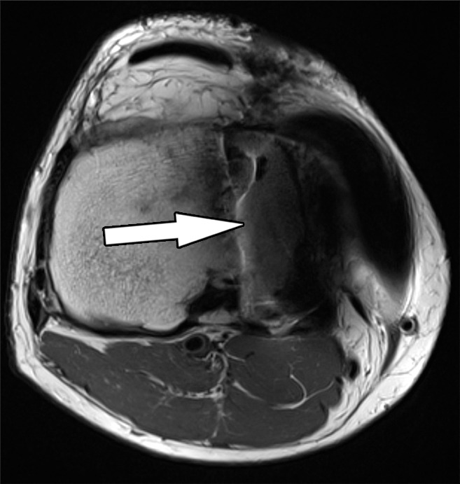
Signal displacement in the section-select (through-plane) direction in a 48-year-old man with a unicondylar knee arthroplasty implant. Axial intermediate-weighted fast spin-echo (SE) (a) and intermediate-weighted section encoding for metal artifact correction (SEMAC) (b) MR images of the same anatomic location demonstrate the spatial misrepresentation of the tibial component (arrow in a) owing to through-plane signal displacement, which is minimized with the SEMAC technique (arrow in b).
Figure 1b.
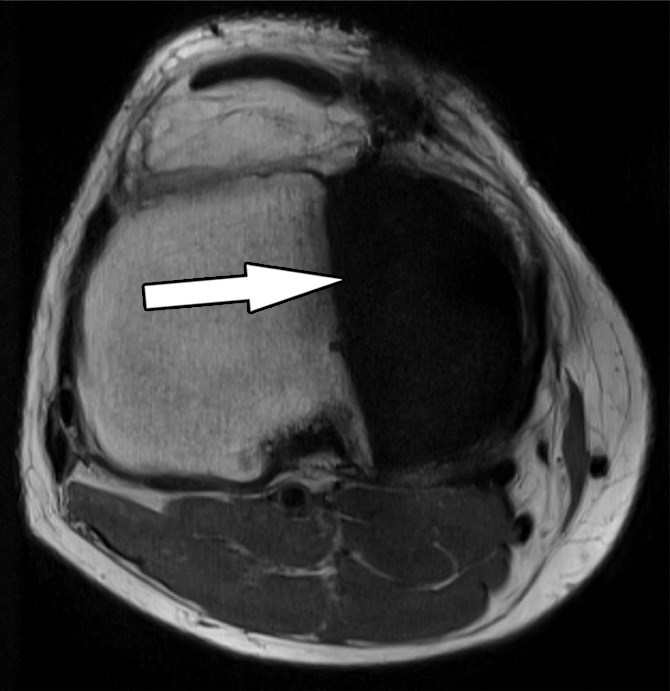
Signal displacement in the section-select (through-plane) direction in a 48-year-old man with a unicondylar knee arthroplasty implant. Axial intermediate-weighted fast spin-echo (SE) (a) and intermediate-weighted section encoding for metal artifact correction (SEMAC) (b) MR images of the same anatomic location demonstrate the spatial misrepresentation of the tibial component (arrow in a) owing to through-plane signal displacement, which is minimized with the SEMAC technique (arrow in b).
Accelerated spin dephasing can be minimized by the 180° radiofrequency spin refocusing pulses of fast SE pulse sequences, which are generally more effective than the gradient-based, spin-refocusing techniques of gradient-echo pulse sequences, which can amplify metal artifacts. If gradient-echo sequences are used, such as for MR angiography, minimizing the echo time will help to limit spin dephasing and preserve signal-to-noise ratio.
Increasing the amplitudes of the frequency-encoding gradient through the use of a higher readout bandwidth and of the frequency-based section-select gradient through the use of thinner sections are powerful means of decreasing signal displacement effects. The use of view-angle tilting techniques can further diminish the magnitude of in-plane signal displacement. The resulting shorter interecho spacing of high-gradient fast SE techniques permits longer echo trains, which shortens acquisition time. Increasing the number of pixels in either the frequency- or the phase-encoding direction, or both, improves the definition of the interfaces of metal artifacts and tissues.
Specific techniques, such as section encoding for metal artifact correction (SEMAC) (15) and multiacquisition variable-resonance image combination (MAVRIC) (16), have been developed to further decrease artifacts and can drastically improve MR imaging along implant-tissue interfaces (Fig 2). Both techniques facilitate powerful correction of through-plane distortions near metal, use multiple excitations to excite the overall volume being imaged, and use three-dimensional SE acquisition to resolve through-plane distortion, which can yield a residual distortion of about one pixel or less. MAVRIC excites limited frequency bands, whereas SEMAC excites limited spatial bands (12).
Figure 2a.
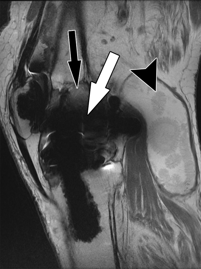
Bone-cement interface visualization along metallic knee arthroplasty implants in a 79-year-old man. Sagittal intermediate-weighted fast SE (a) and MAVRIC (b) MR images of the same anatomic location demonstrate improved visualization of the femoral bone–cement interface (white arrow) and improved visualization of femoral osteolysis (black arrow). Additionally, there is a polyethylene wear–induced synovitis with a large joint effusion and many joint bodies (arrowhead).
Figure 2b.
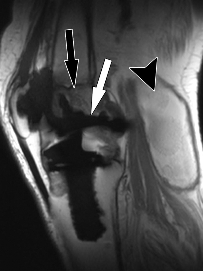
Bone-cement interface visualization along metallic knee arthroplasty implants in a 79-year-old man. Sagittal intermediate-weighted fast SE (a) and MAVRIC (b) MR images of the same anatomic location demonstrate improved visualization of the femoral bone–cement interface (white arrow) and improved visualization of femoral osteolysis (black arrow). Additionally, there is a polyethylene wear–induced synovitis with a large joint effusion and many joint bodies (arrowhead).
To regain the signal lost through these modifications and techniques, a higher number of excitations is generally needed. Long repetition times and intermediate echo times contribute to signal increase and overall improvement in contrast-to-noise ratios of musculoskeletal tissues.
Spectral fat-suppression techniques fail around implants because of the altered precession frequencies and altered separation of fat- and water-bound spins that result in a mismatch with the suppression radiofrequency pulse. Short inversion time inversion-recovery (STIR) pulse sequences achieve a more homogeneous fat suppression, because this technique is based on the T1 recovery time constants, which are less affected by the effects of metal. With higher-magnitude field inhomogeneities, a wider-bandwidth spin excitation radiofrequency pulse can improve homogeneity of fat suppression (17).
Acquisition of contrast material–enhanced MR images is not routinely required in these cases, but can be reliably achieved by use of T1-weighted fast SE pulse sequences with optimization for metal artifact reduction, as previously described. Fat suppression can be achieved through subtraction of a precontrast image from an identical postcontrast image.
Practical Considerations
MR imaging is best performed with the patient in the supine position. Circular multichannel surface coils facilitate high-spatial-resolution imaging and fit most patients. Wrap coils may be suitable for patients with large knees. A suggested pulse sequence protocol is given in the Table.
Protocol for 1.5-T MR Imaging of Knee Arthroplasty Implants
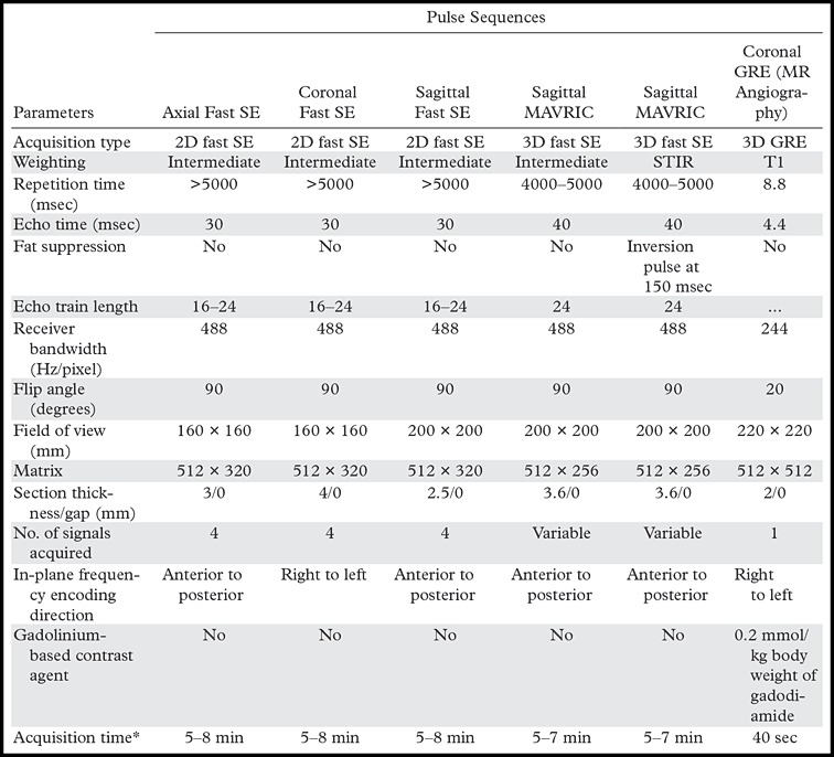
Note.—GRE = gradient echo, 3D = three-dimensional, 2D = two-dimensional.
*Depends on the number of sections required to cover anatomy; given ranges are typical of clinical application.
Intermediate-weighted fast SE pulse sequences with high spatial resolution are most versatile for imaging around knee arthroplasty implants because of the high signal-to-noise ratio, sensitivity to fluid, and favorable contrast-to-noise ratios, which allow sensitive detection and accurate characterization of periprosthetic bone and soft tissues. T2-weighted images with echo times greater than 50 msec are subject to poor signal and low contrast-to-noise ratios, and T1-weighted images provide a poor fluid-to-synovium contrast ratio.
The MR images should include the entire knee in anteroposterior and mediolateral directions, and extend superoinferiorly from the distal quadriceps tendon to below the tibial tuberosity. The coronal plane should include the femoral insertion of the superficial portion of the medial collateral ligament distally.
Axial images are most useful for evaluating the bone-implant interface around the patellar and tibial components. Additionally, axial images demonstrate the synovial lining, the presence of a popliteal cyst, the semimembranosus tendon, and the neurovascular structures about the knee.
Sagittal images are most useful for evaluating the bone-implant interface of the femoral as well as of the patellar and tibial components. Additionally, sagittal images demonstrate the extensor mechanism well.
Coronal images are most useful for evaluating the bone-implant interface of the tibial components. The collateral ligaments, the popliteus tendon insertion, and popliteus muscle quality are well evaluated on coronal images.
Intermediate-weighted and STIR MAVRIC and SEMAC images are helpful in unmasking stress reactions, stress fractures, periprosthetic bone resorption, and osteolysis in the immediate vicinity of implants, as well as synovitis, joint fluid, soft-tissue edema, and fluid collections.
Knee Arthroplasty Implant Design
Implant design and terminology vary between manufacturers and surgeons. Total knee arthroplasty usually describes resurfacing of the medial and lateral femorotibial compartments and the patellofemoral compartment. The major implant categories include posterior cruciate ligament (PCL)–retaining, PCL-substituting or posterior-stabilized, unlinked constrained or varus-valgus constrained, and rotating-hinge knee implants (18). Unicompartmental knee arthroplasty describes the resurfacing of either one femorotibial compartment or of the patellofemoral compartment. Optimized MR imaging has been shown to allow evaluation of the preserved compartments with reproducible results (19,20). Implant components are often made from cobalt (Co)-chromium (Cr) alloys. Oxidized zirconium (Zr) alloys cause fewer field alterations than Co-Cr alloys, due to the diminished magnetic moment of Zr (21,22).
MR Imaging Appearance of Complications
Common complications of knee arthroplasty include polyethylene wear (25%), aseptic loosening (24%), instability (21%), infection (17%), arthrofibrosis (15%), malalignment or malposition (12%), extensor mechanism deficiency (6.6%), avascular necrosis of the patella (4.2%), and periprosthetic fractures (2.8%) (23). Given the number of structures that need to be assessed in patients with knee arthroplasty implants, we suggest a structured approach to image interpretation and reporting (Appendix).
Bone Resorption
Solid osseous fixation of knee arthroplasty implants is one of the most critical factors for achievement of pain-free joint function and implant longevity. Durable implant fixation into the host bone can be achieved surgically through cementation or through ingrowth of bone trabeculae into porous-coated, uncemented implants.
Component loosening, which is often progressive in nature, is characterized by separation along the bone-implant interface. Initially, pain with activity and weight bearing predominate, eventually leading to implant dysfunction with frank shift and rotation of components. Contributing factors are incomplete cementation, suboptimal component alignment, bone defects, sclerotic bone along the implant interface, osteonecrosis, eccentric component position, inadequate ligamentous balancing, inaccurate osseous cuts of femoral components, and varus tilt of the tibial component (24). The proposed underlying cause is micromotion between the implant or cement surface, or both, and the host bone. The associated mechanical stress is thought to promote the migration of synoviocytes into the space along the cement-bone and implant-bone interfaces, which then create a “synovium-like” or “fibrous” membrane and release osteoclast-stimulating cytokines that contribute to adjacent bone resorption (25). The presence of fibrous membrane formation indicates limited implant fixation, which may or may not progress to component loosening but may warrant closer imaging surveillance (26).
At MR imaging, an intact interface is visualizable as direct contact of both cement and implant with surrounding bone, forming a sharp interface (Fig 3). Fibrous membrane formation is visualizable as a thin layer of high signal intensity on intermediate-weighted and STIR MR images of the interface between the host bone and the implant or cement (Fig 4). As it would be with radiography and computed tomography (CT) (13), a 1–2 mm thick layer with smooth margins of the bone interface seen on MR images may be qualified as fibrous membrane formation, whereas a layer of greater than 2-mm thickness with irregular margins may be qualified as bone resorption (Fig 5). With circumferential involvement and increasing width of separation along the interface, complete loss of implant fixation becomes more likely. The term loosening should be reserved for cases where MR imaging demonstrates circumferential osseous resorption with such defined signs as implant displacement (Fig 6), rotation, and subsidence.
Figure 3a.
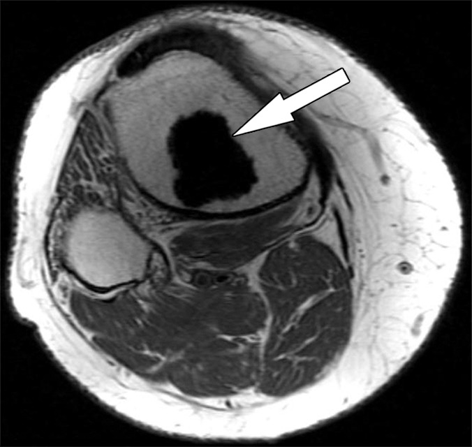
Solid osseous implant integration after total knee arthroplasty in a 63-year-old woman. Axial intermediate-weighted fast SE MR images of a tibial (a) and a patellar (b) component demonstrate direct contact of the cement and the surrounding cancellous bone (arrow).
Figure 4a.
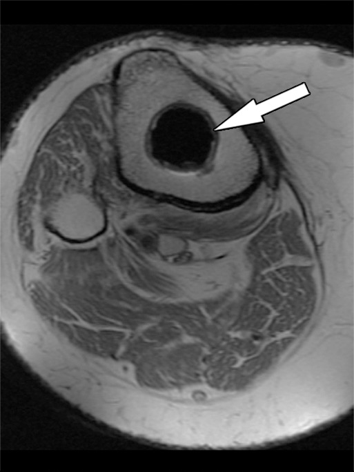
Fibrous membrane formation after total knee arthroplasty in a 70-year-old man. Axial intermediate-weighted fast SE images show a thin layer of increased signal intensity at the implant-bone interface of the tibial (arrow in a) and patellar (arrow in b) components, which is surrounded by a thin layer of decreased signal intensity.
Figure 5a.
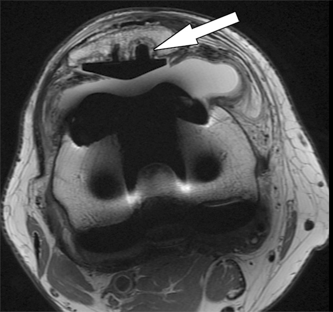
Periprosthetic bone resorption after total knee arthroplasty in a 77-year-old woman. Axial (a) and sagittal (b) intermediate-weighted fast SE MR images demonstrate bone resorption at the implant-cement interfaces of the patellar (arrow in a), femoral (white arrow in b), and tibial (black arrow in b) components, seen as irregular layers of increased signal intensity, which are surrounded by a layer of decreased signal intensity. Additionally, there is synovitis visible on the images.
Figure 6.
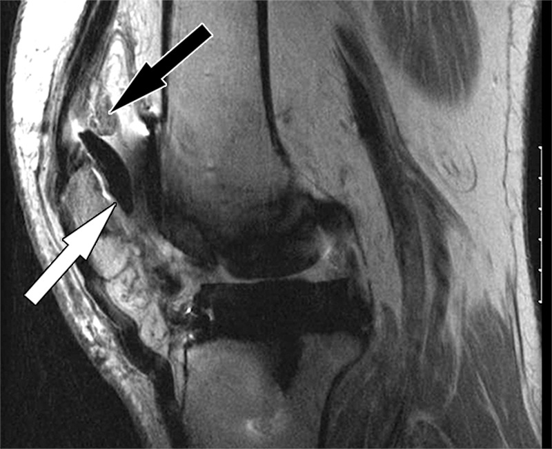
Implant loosening after total knee arthroplasty in a 75-year-old man. Sagittal intermediate-weighted fast SE image shows a displaced patellar component (white arrow). Note the synovial proliferations in the suprapatellar recess (black arrow).
Figure 3b.
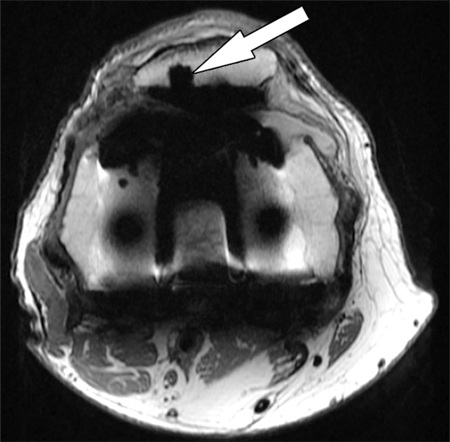
Solid osseous implant integration after total knee arthroplasty in a 63-year-old woman. Axial intermediate-weighted fast SE MR images of a tibial (a) and a patellar (b) component demonstrate direct contact of the cement and the surrounding cancellous bone (arrow).
Figure 4b.
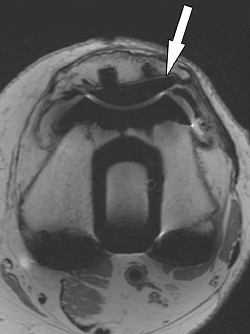
Fibrous membrane formation after total knee arthroplasty in a 70-year-old man. Axial intermediate-weighted fast SE images show a thin layer of increased signal intensity at the implant-bone interface of the tibial (arrow in a) and patellar (arrow in b) components, which is surrounded by a thin layer of decreased signal intensity.
Figure 5b.
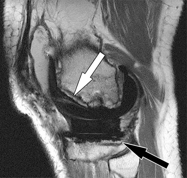
Periprosthetic bone resorption after total knee arthroplasty in a 77-year-old woman. Axial (a) and sagittal (b) intermediate-weighted fast SE MR images demonstrate bone resorption at the implant-cement interfaces of the patellar (arrow in a), femoral (white arrow in b), and tibial (black arrow in b) components, seen as irregular layers of increased signal intensity, which are surrounded by a layer of decreased signal intensity. Additionally, there is synovitis visible on the images.
Polyethylene Wear and Osteolysis
Polyethylene wear is one of the primary means by which knee arthroplasty fails over time (23). Polyethylene wear occurs through a combination of complex motions, primarily along the articulations of the tibial polyethylene insert and the metallic femoral component, but also between the tibial polyethylene insert and metal baseplate (27). Over time, surface wear leads to delamination, pitting, and fatigue failure of the implant, thereby releasing different sizes of particles (28). This wear and release of particles is usually associated with painful synovitis, crepitus, and grinding with joint motion.
Following, and as a result of, their phagocytosis by macrophages, the smallest polyethylene-wear particles induce a cytokine-mediated, intra-articular, inflammatory reaction, which is often referred to as “particle disease” (29). This inflammatory process typically starts as a proliferative, polyethylene wear–induced synovitis, which can manifest as new-onset joint pain and effusion. Over time, polyethylene particles migrate into bone-cement and bone-implant interfaces and cause geographic osteolysis through cytokine-mediated upregulation of osteoclasts and downregulation of osteoblasts (30). Although this process often progresses slowly, osteolysis eventually causes loosening of knee arthroplasty implants and warrants surveillance as well as timed revision.
Imaging is useful for identification of osteolysis, monitoring of bone loss, and preoperative quantification of osteolysis. As with hip arthroplasty (13), the projectional, two-dimensional nature of conventional radiography of total knee arthroplasty is often insensitive for accurate visualization of the three-dimensional extent of bone loss (31,32). CT with postprocessing by using metal-induced beam-hardening suppression can be more accurate than radiography, as has been shown for pelvic osteolysis (33). MR imaging is accurate for localizing and quantifying the magnitude of bone loss around curved implants as well as for the assessment of the intracapsular burden of particle disease (34,35). In a cadaveric model of periacetabular osteolysis, MR imaging had a sensitivity for lesion detection of 95% versus 75% for optimized CT and 52% for plain radiographs (36). In another cadaveric study, MR imaging had a detection accuracy of 96% for periacetabular osteolysis with a mean absolute error of 0.8 cm3 in determining lesion size (37). MR imaging enables the serial evaluation of painful and asymptomatic prosthetic joints without associated exposure to ionizing radiation.
At MR imaging, polyethylene wear–induced synovitis is typically characterized by synovial thickening with dense synovial proliferation and debris with low-to-intermediate signal intensity (similar to the intensity of skeletal muscle), with variable amounts of interspersed fluid and joint distention (Fig 7). With an increasing burden of intracapsular synovial proliferation and debris, bone erosions can occur (Fig 8). The formation of polyethylene granulomas or focal expansion of the capsule can cause regional neurovascular compression. Polyethylene wear–induced osteolysis is typically geographic and contains particulate debris of intermediate signal intensity that replaces the normal periprosthetic trabecular bone and high-signal-intensity fat of the marrow (Figs 2, 9). This sharp contrast resolution allows for segmentational quantitative volumetry of osteolysis for longitudinal monitoring (34).
Figure 7.
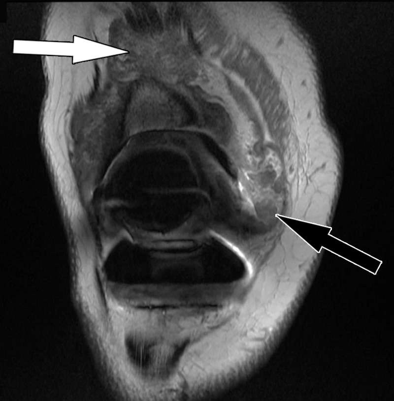
Polyethylene wear–induced synovitis after total knee arthroplasty in a 79-year-old man. Coronal intermediate-weighted fast SE image shows dense synovial proliferations (white arrow) and low-to-intermediate-signal-intensity debris (black arrow), similar to the signal intensity of skeletal muscle.
Figure 8.
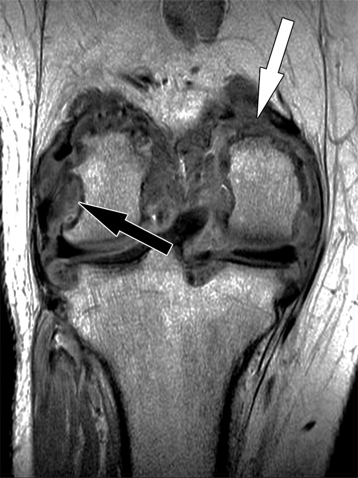
Polyethylene wear–induced synovitis with erosion after total knee arthroplasty in an 88-year-old woman. Coronal intermediate-weighted fast SE image shows dense synovial proliferations, low-to-intermediate-signal-intensity debris (white arrow), and a dominant erosion at the lateral femoral condyle (black arrow) and tibial plateau.
Figure 9a.
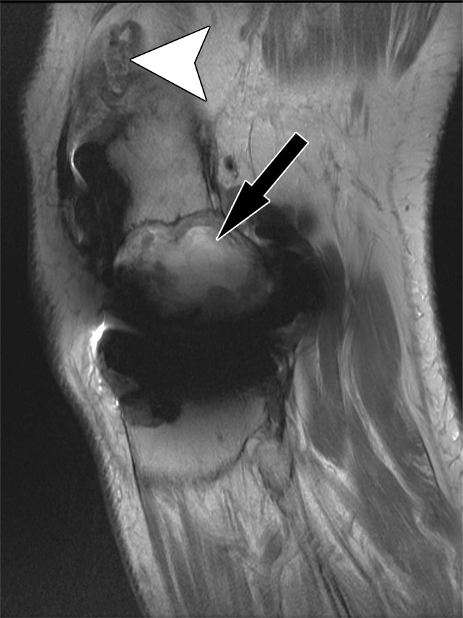
Polyethylene wear–induced synovitis and osteolysis after total knee arthroplasty in a 70-year-old man. Sagittal intermediate-weighted fast SE (a) and STIR MAVRIC (b) MR images show a polyethylene wear–induced synovitis with dense synovial proliferations, low-to-intermediate-signal-intensity debris (arrowhead), and extensive osteolysis of the distal femur (arrow) as indicated by hyperintense signal on the STIR MAVRIC image (arrow in b).
Figure 9b.
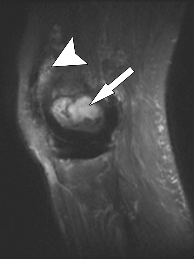
Polyethylene wear–induced synovitis and osteolysis after total knee arthroplasty in a 70-year-old man. Sagittal intermediate-weighted fast SE (a) and STIR MAVRIC (b) MR images show a polyethylene wear–induced synovitis with dense synovial proliferations, low-to-intermediate-signal-intensity debris (arrowhead), and extensive osteolysis of the distal femur (arrow) as indicated by hyperintense signal on the STIR MAVRIC image (arrow in b).
Instability
Instability following knee arthroplasty can have many causes, including implant failure, preoperative deformity, component alignment, intraoperative soft-tissue balancing, and ligament and tendon tears (38). Mediolateral instability is the most common type of instability and is associated with tibial component loosening and catastrophic implant failure (39). MR imaging allows accurate evaluation of the integrity of the critical posteromedial stabilizers, including the superficial medial collateral ligament, posterior oblique ligament, and capsular semimembranosus insertion (Fig 10), as well as of the posterolateral stabilizers, including the lateral collateral ligament and the popliteus muscle-tendon unit (Figs 11, 12). Posterior instability is exacerbated by quadriceps and patellar tendon tears. Anteroposterior and flexion instability of relatively unconstrained PCL-retaining arthroplasty systems can occur with inadvertently sectioned, improperly balanced, and delayed full-thickness tear of the PCL (40), thereby allowing posterior dislocation of the tibial component. Due to the low magnetic susceptibility of polyethylene, MR imaging is well suited for the detection of fractured polyethylene arthroplasty components (Figs 13, 14).
Figure 10.
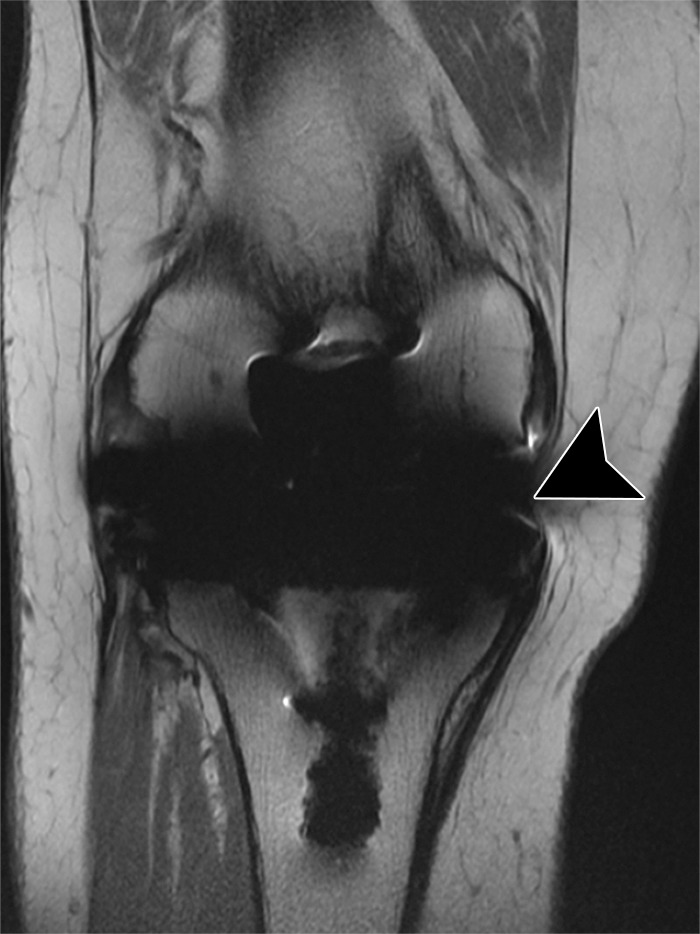
Medial instability after total knee arthroplasty in a 71-year-old man. Coronal intermediate-weighted fast SE image shows a deficient superficial component of the medial collateral ligament (arrowhead).
Figure 11.
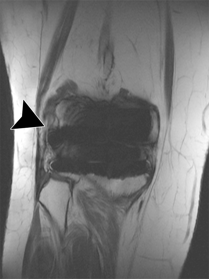
Lateral instability after total knee arthroplasty in a 60-year-old woman. Coronal intermediate-weighted fast SE image shows a chronic, high-grade partial thickness tear of the proximal lateral collateral ligament (arrowhead).
Figure 12a.
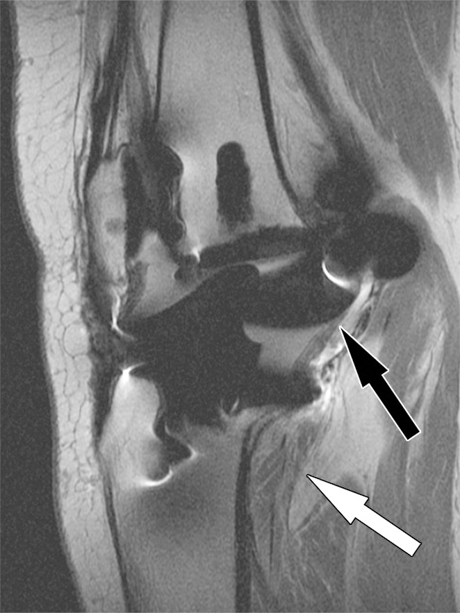
Posterior instability after total knee arthroplasty in a 54-year-old man. Sagittal (a) and coronal (b) intermediate-weighted fast SE images show posterior subluxation (black arrow in a) of the femur due to a chronically torn popliteus tendon (black arrow in b) as indicated by atrophy and fatty infiltration of the popliteus muscle bulk (white arrow).
Figure 13.
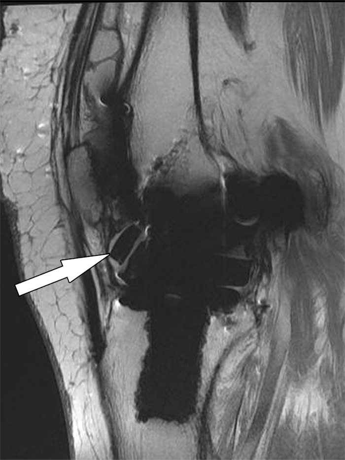
Instability after total knee arthroplasty in a 56-year-old man. Sagittal intermediate-weighted fast SE image shows a fragment (arrow) of a fractured polyethylene insert located in the anterior joint recess.
Figure 14.
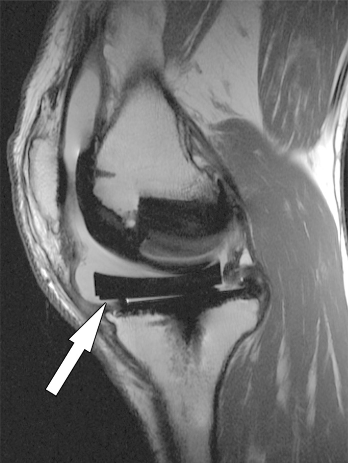
Displacement of the liner after total knee arthroplasty in a 52-year-old man. Sagittal intermediate-weighted fast SE image shows an anteriorly displaced polyethylene insert (arrow).
Figure 12b.
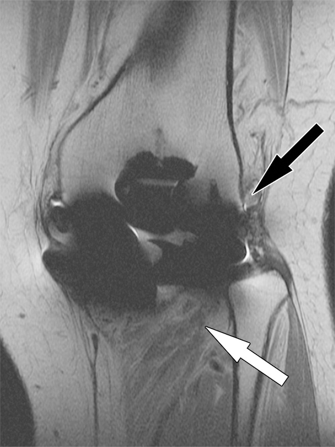
Posterior instability after total knee arthroplasty in a 54-year-old man. Sagittal (a) and coronal (b) intermediate-weighted fast SE images show posterior subluxation (black arrow in a) of the femur due to a chronically torn popliteus tendon (black arrow in b) as indicated by atrophy and fatty infiltration of the popliteus muscle bulk (white arrow).
Periprosthetic Joint Infection
Infection is one of the most devastating and difficult-to-manage complications following knee arthroplasty. Timely diagnosis is the top goal in preserving joint function, containing tissue damage, avoiding systemic sepsis, and limiting use of hospital and physician resources (41). Classic signs and symptoms, such as wound drainage, erythema, joint swelling, fever, chills, and generalized malaise, carry a high pretest likelihood; however, many periprosthetic infections do not manifest those obvious signs and symptoms (38). The prevalence of periprosthetic knee infection ranges between 1% and 2% and is significantly higher than that for hip implants, which is 0.88% (42). The most common organisms for the former are staphylococci (48%–66%) and streptococci (9%–10%), as well as enterococci, gram-negative bacilli, and anaerobes (43). Inflammatory arthritis, previous surgery, diabetes, steroid use, poor nutrition, old age, obesity, recurrent urinary tract infection, dental infections, skin ulcerations, and distal extremity infections are factors associated with an increased rate of periprosthetic infection after knee arthroplasty (44). Two-stage revision arthroplasty is the treatment of choice for periprosthetic infection of the knee in North America.
Arthroplasty-associated infections can be classified by the time of occurrence and pattern of presentation into different types (45). An acute infection that occurs within 2 months after surgery often manifests as swelling and erythema and may be due to a wound complication or hematoma. An intermediate infection manifests between 2 and 24 months after surgery and often requires differentiation from a mechanical cause of pain. Late infection occurs 2 years or more after the index arthroplasty and is often hematogenously seeded, associated with a distant infection.
MR imaging can contribute helpful information in patients with suspected periprosthetic joint infection (46). The MR imaging findings of a lamellated synovitis with hyperintense signal, extracapsular soft-tissue edema, extracapsular collections, and reactive lymphadenopathy carry a high likelihood for the presence of a periprosthetic joint infection (Fig 15). In a retrospective case-control study (46), MR imaging findings of lamellated hyperintense synovitis were 86–92% sensitive and 85%–87% specific for periprosthetic joint infection. There was substantial interobserver and intraobserver agreement for the classification of the synovial pattern, indicating the ability of MR imaging to allow distinction of infectious and different patterns of wear-induced synovitis (46,47). In acute infections, MR imaging can demonstrate the presence of a wound complication such as a hematoma or abscess. In patients with a pretest high likelihood based on clinical presentation and laboratory testing, MR imaging demonstration of a sinus tract is diagnostic for joint infection (48). Ultimately, conclusive joint aspiration or tissue sampling or both are required for diagnosis of a periprosthetic infection and determination of the specific organism (49). In cases with possible periprosthetic infection but discrepant laboratory test results and inconclusive joint aspiration results, MR imaging findings suggestive of infectious synovitis should trigger repetition of the workup (50).
Figure 15a.
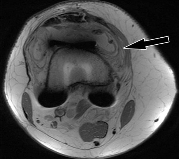
Periprosthetic joint infection after total knee arthroplasty in a 60-year-old man. Axial (a) and sagittal (b) intermediate-weighted fast SE and axial STIR (c) MR images demonstrate thickening, layering or lamellation, and signal hyperintensity of the synovium (arrow) with expansion of the joint capsule. Joint aspiration and microbiological analysis resulted in identification of Staphylococcus aureus bacteria.
Figure 15b.
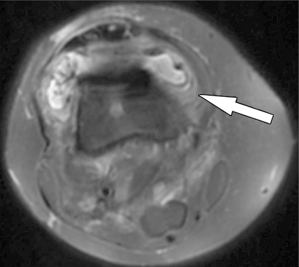
Periprosthetic joint infection after total knee arthroplasty in a 60-year-old man. Axial (a) and sagittal (b) intermediate-weighted fast SE and axial STIR (c) MR images demonstrate thickening, layering or lamellation, and signal hyperintensity of the synovium (arrow) with expansion of the joint capsule. Joint aspiration and microbiological analysis resulted in identification of Staphylococcus aureus bacteria.
Figure 15c.
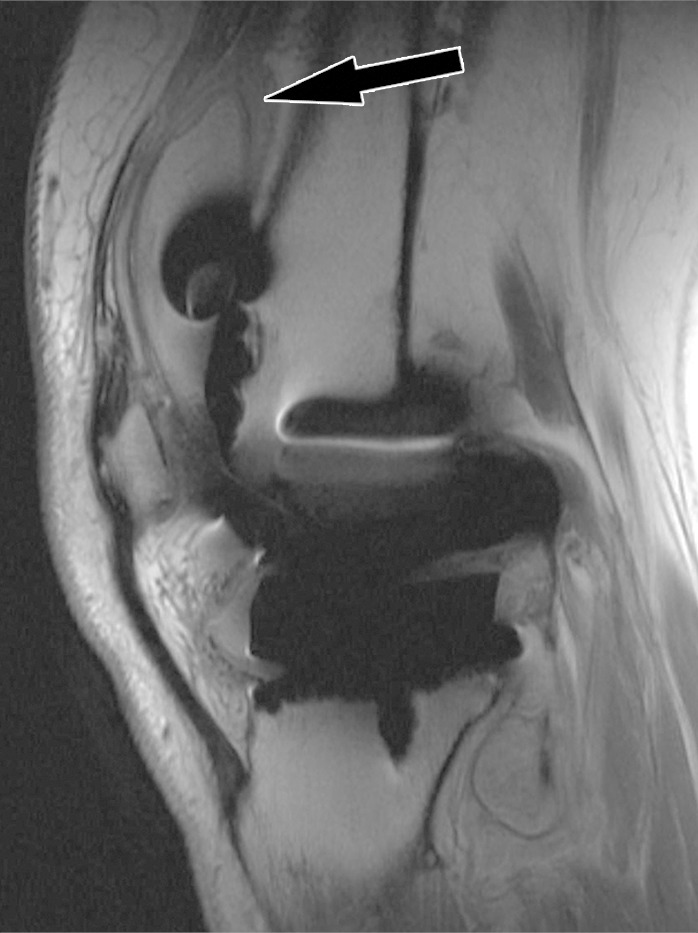
Periprosthetic joint infection after total knee arthroplasty in a 60-year-old man. Axial (a) and sagittal (b) intermediate-weighted fast SE and axial STIR (c) MR images demonstrate thickening, layering or lamellation, and signal hyperintensity of the synovium (arrow) with expansion of the joint capsule. Joint aspiration and microbiological analysis resulted in identification of Staphylococcus aureus bacteria.
Component Malalignment
Accurate rotational alignment of implant components is an important factor for satisfactory joint function and implant survival (23). Increased internal or external rotation of the femoral component can cause increased tibiofemoral wear, worsen patellar tracking, and contribute to subluxation, dislocation, patellar clunk, and eccentric wear (51). Combined femoral and tibial component internal malrotation has been associated with the presence of a painful synovitis and a fivefold increase in the likelihood of experiencing anterior knee pain (52). Internal rotational errors, involving the femoral, the tibial, or both components, were found in 56.4% of patients with painful total knee arthroplasty (53). Varying configurations of malrotation exist, including combined component external rotation, tibial component internal mismatch, tibial component external mismatch, and combined component internal rotation.
MR imaging is accurate for the identification of the anatomic landmarks and the axes required for measurement and calculation of the rotational alignment parameters (21,52,54). Interobserver agreement was found to be higher for femoral zirconium (Zr) implants than for cobalt (Co)/chrome (Cr)/molybdenum (Mo) alloy femoral components, likely due to larger susceptibility artifacts for the latter (21). Rotational alignments for tibial components generally demonstrate higher variation, which likely relates to the more complex geometric method used for this measurement rather than to the imaging modality used.
Because of the resection of the trochlea and posterior condyles during arthroplasty, the surgical transepicondylar axis is often used to assess femoral component rotation (Fig 16). This axis has been shown to be the functional flexion-extension axis of the knee and is defined as the line connecting the most prominent point of the lateral epicondyle with the medial epicondylar sulcus. MR imaging may be more accurate than plain radiography or CT in the visualization of the medial epicondylar sulcus (52), as two CT studies identified the medial epicondylar sulcus in only 69%–73% of patients (55,56). The ideal rotational angle between the surgical femoral transepicondylar axis and the femoral component axis is considered to be 0° (52).
Figure 16.
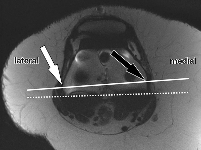
Determination of the rotational angle of the femoral component after total knee arthroplasty in a 63-year-old woman. Axial intermediate-weighted fast SE image demonstrates the surgical femoral transepicondylar axis (solid line) as the line connecting the most prominent point of the lateral epicondyle (white arrow) with the medial epicondylar sulcus (black arrow). The femoral component axis is determined by the tangent (dotted line) along the anterior margin of the posterior condylar backing. The rotational angle of the femoral component is the angle between the two lines as visualized on a single axial MR image.
Measurement of the rotational angle of the tibial component relative to the tibia requires determination of the tibial tubercle axis and tibial component anteroposterior axis (Fig 17), which ideally should measure 18° of internal rotation (52). Exceptions include asymmetric tibial tray designs.
Figure 17a.
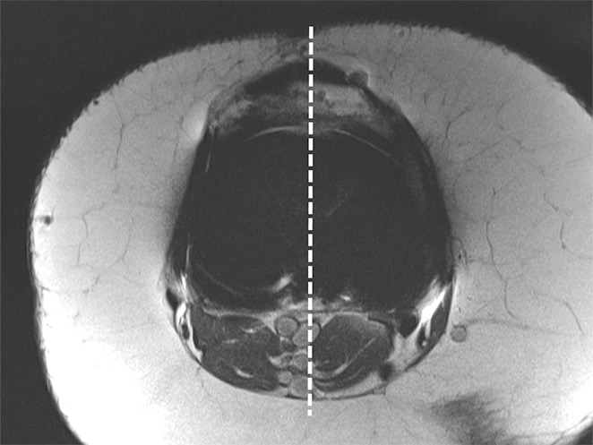
Determination of the rotational angle of the tibial component after total knee arthroplasty in a 63-year-old woman. (a) Axial intermediate-weighted fast SE image demonstrates the tibial component anteroposterior axis, which intersects the center of the anterior and posterior margins of the tibial component. (b) Axial intermediate-weighted fast SE image demonstrates determination of the geometric center of the tibia plateau (x) by a best-fit ellipse (solid line) circumscribing the tibial cortex. (c) Axial intermediate-weighted fast SE image demonstrates the tibial tubercle axis (solid line) as the line connecting the determined geometric center of the tibia (x in b–d) through the center (arrow) of the tibial tubercle. (d) Axial intermediate-weighted fast SE image demonstrates the rotational angle of the tibial component measured as the angle between the tibial tubercle axis (solid line in c and d) and tibial component axis (dashed line in a and d).
Figure 17b.
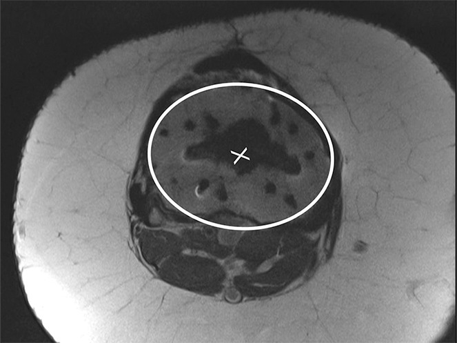
Determination of the rotational angle of the tibial component after total knee arthroplasty in a 63-year-old woman. (a) Axial intermediate-weighted fast SE image demonstrates the tibial component anteroposterior axis, which intersects the center of the anterior and posterior margins of the tibial component. (b) Axial intermediate-weighted fast SE image demonstrates determination of the geometric center of the tibia plateau (x) by a best-fit ellipse (solid line) circumscribing the tibial cortex. (c) Axial intermediate-weighted fast SE image demonstrates the tibial tubercle axis (solid line) as the line connecting the determined geometric center of the tibia (x in b–d) through the center (arrow) of the tibial tubercle. (d) Axial intermediate-weighted fast SE image demonstrates the rotational angle of the tibial component measured as the angle between the tibial tubercle axis (solid line in c and d) and tibial component axis (dashed line in a and d).
Figure 17c.
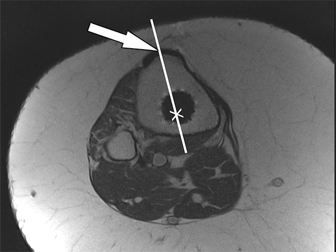
Determination of the rotational angle of the tibial component after total knee arthroplasty in a 63-year-old woman. (a) Axial intermediate-weighted fast SE image demonstrates the tibial component anteroposterior axis, which intersects the center of the anterior and posterior margins of the tibial component. (b) Axial intermediate-weighted fast SE image demonstrates determination of the geometric center of the tibia plateau (x) by a best-fit ellipse (solid line) circumscribing the tibial cortex. (c) Axial intermediate-weighted fast SE image demonstrates the tibial tubercle axis (solid line) as the line connecting the determined geometric center of the tibia (x in b–d) through the center (arrow) of the tibial tubercle. (d) Axial intermediate-weighted fast SE image demonstrates the rotational angle of the tibial component measured as the angle between the tibial tubercle axis (solid line in c and d) and tibial component axis (dashed line in a and d).
Figure 17d.
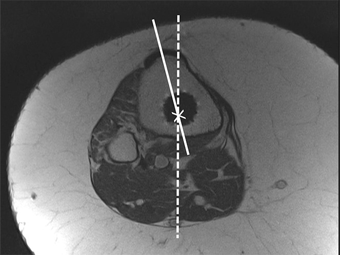
Determination of the rotational angle of the tibial component after total knee arthroplasty in a 63-year-old woman. (a) Axial intermediate-weighted fast SE image demonstrates the tibial component anteroposterior axis, which intersects the center of the anterior and posterior margins of the tibial component. (b) Axial intermediate-weighted fast SE image demonstrates determination of the geometric center of the tibia plateau (x) by a best-fit ellipse (solid line) circumscribing the tibial cortex. (c) Axial intermediate-weighted fast SE image demonstrates the tibial tubercle axis (solid line) as the line connecting the determined geometric center of the tibia (x in b–d) through the center (arrow) of the tibial tubercle. (d) Axial intermediate-weighted fast SE image demonstrates the rotational angle of the tibial component measured as the angle between the tibial tubercle axis (solid line in c and d) and tibial component axis (dashed line in a and d).
The femoral to tibial component alignment angle should ideally be 0° (52).
Arthrofibrosis
Arthrofibrosis is a complication following knee arthroplasty that is characterized by chronic pain, global capsular contraction, and progressive loss of range of motion, and can advance to complete joint stiffness (57). The prevalence following knee arthroplasty ranges between 3% and 4%. Arthrofibrosis is caused by the formation of dense fibrous tissue along the synovial lining of the entire joint (58). A proposed mechanism is excessive fibroplasia with resulting tissue adhesions and impairment of the extensor mechanism of the knee.
MR imaging can be helpful in the diagnosis of arthrofibrosis in patients with suboptimal range of motion despite good radiographic appearance of their arthroplasty implants (Fig 18). The high soft-tissue contrast of MR imaging allows for the direct visualization of synovial scarring. MR imaging findings of arthrofibrosis include heterogeneous thickening of the synovial lining, which may demonstrate a nodular component. The signal intensity of the scarred synovium is typically less than that of skeletal muscle on intermediate-weighted MR images. In addition, MR imaging can diagnose other postoperative causes of inadequate range of motion, such as infection, heterotopic ossification, and patellar complications such as fracture and patellar component loosening (57).
Figure 18.
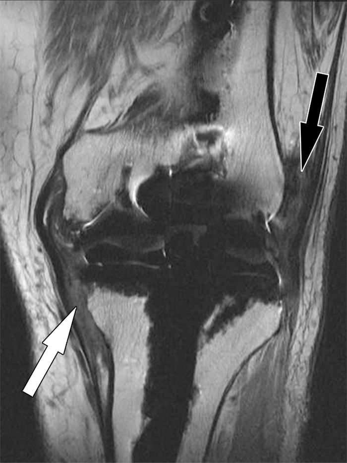
Arthrofibrosis after total knee arthroplasty in an 82-year-old man. Coronal intermediate-weighted fast SE image shows low-to-intermediate-signal-intensity fibrotic tissue proliferation obliterating the medial (white arrow) and the lateral (black arrow) gutters.
Patellar Clunk Syndrome
Patellar clunk syndrome is a patellofemoral complication that manifests with a locking sensation or impaired motion during flexion and extension in up to 3.5% of posterior-stabilized total knee arthroplasties (59). At physical examination, an audible and often painful clunking occurs with extension of the knee. The syndrome is caused by formation of focal fibrous tissue at the junction of the proximal patellar pole and the quadriceps tendon, occurring a mean of 10.6 months after total knee arthroplasty (60). One proposed mechanism is that fibrous tissue enters into the intercondylar notch with flexion, and is then displaced in extension, resulting in the audible clunk (61). Among the treatment options is resection of the fibrous tissue, for which an arthroscopic approach has been described as more successful than an open approach (62).
MR imaging allows accurate characterization of intra-articular soft-tissue proliferation in patients with clinically manifest patellar clunk syndrome (Fig 19), aiding in the decision process with respect to proceeding with arthroscopic débridement (61). In a 12-patient cohort, MR imaging demonstrated intra-articular soft-tissue masses in 75% of the cases. In all cases, the tissue was located proximally to the patella, well-marginated, and of intermediate-to-low signal intensity on intermediate-weighted MR images. The average lesion size was 7–10 mm in the anteroposterior dimension, 17 mm in the craniocaudal dimension, and 33 mm in the transverse dimension. A reproducible interobserver reliability of the radiologic measurements was demonstrated. On the basis of the study results, the authors concluded that because of the limitations of conventional radiographs in characterizing soft-tissue lesions, the multiplanar capabilities and superior soft-tissue contrast render MR imaging the method of choice.
Figure 19.
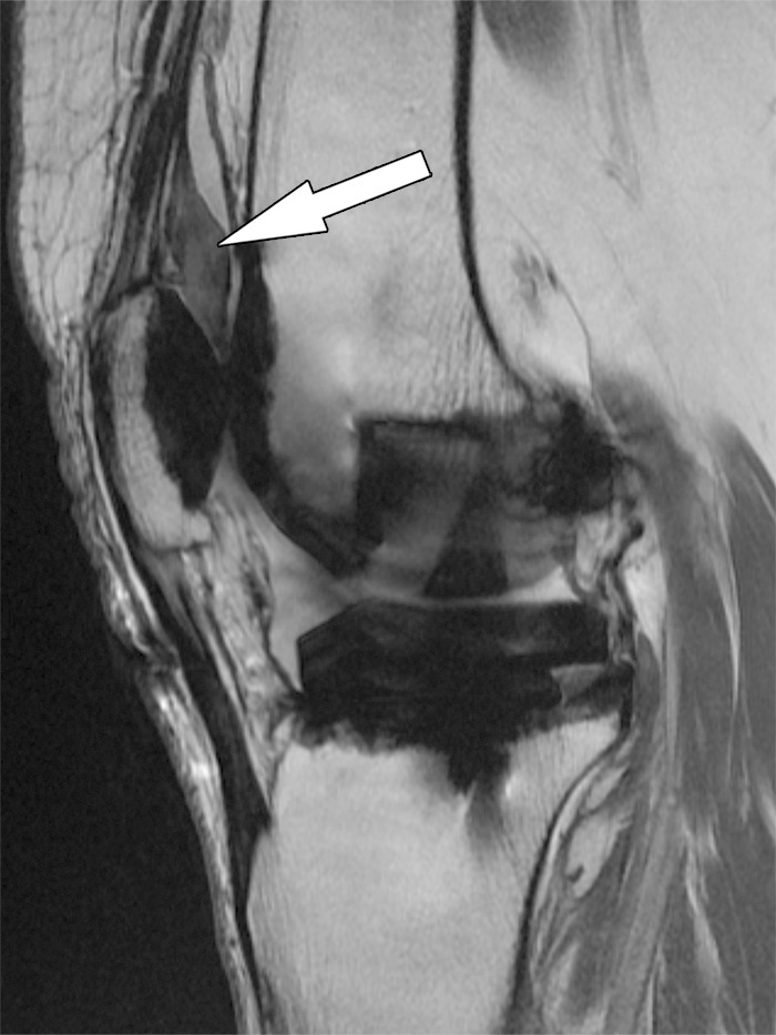
Patellar clunk syndrome after total knee arthroplasty in a 64-year-old woman. Coronal intermediate-weighted fast SE image shows a well-marginated, low-to-intermediate-signal-intensity fibrotic mass (arrow) at the proximal patellar margin.
Recurrent Hemarthrosis
Recurrent hemarthrosis is an infrequent complication after total knee arthroplasty that is characterized by painful swelling and often substantial restriction of motion because of the intra-articular accumulation of blood products (63). The interval between knee arthroplasty surgery and first hemorrhagic episode ranges between 2 weeks and 12 years. The estimated prevalence ranges between 0.1% and 1.6% (64). A timely and accurate diagnosis is important for selection of the most appropriate treatment; however, due to the variety of causes, diagnosis often poses a challenge. Inappropriately managed hemarthrosis can lead to poor arthroplasty implant function and occasionally to deep joint sepsis and wound breakdown (64).
The synovium of the knee has a rich vascular supply with major contributions from the medial and lateral superior and inferior genicular arteries, which commonly arise from the popliteal artery. The most common surgical and histologic findings of hemarthrosis occurring late after total knee arthroplasty include hypervascular and proliferative synovium with signs of arthroplasty component impingement, which is more prone to trauma and more likely to bleed (65). Iatrogenic causes such as pseudoaneurysms or arteriovenous fistulas manifest most frequently within the first 6 months after surgery. Additional causes include pigmented villonodular synovitis, loose components, and infection (64,66). Management options include nonsurgical treatment, surgical synovectomy, selective embolization and stent placement, as well as radiosynovectomy.
In a similar fashion to conventional angiography, MR angiography can be successfully used to define the vascular anatomy about the knee and visualized abnormal synovium. MR angiography comes with the advantage of a low level of invasiveness, as it requires only intravenous access rather than arterial catheterization, uses no ionizing radiation, and the gadolinium (Gd)-based contrast agents used have substantially lower risks of allergic reactions and no risk of nephrotoxic effects as compared with the iodinated contrast agents used in conventional angiography. Because intravenous administration of Gd is contraindicated in patients with acute or chronic severe renal insufficiency (glomerular filtration rate, <30 mL/min/1.73 m2), acute renal insufficiency of any severity due to hepatorenal syndrome, in the perioperative hepatic transplant period, and because of the potential complication of nephrogenic systemic fibrosis, patients with impaired renal function should have a recent assessment of glomerular filtration rate before undergoing MR angiography. The combination of MR angiography and MR imaging allows for additional assessment of adjacent osseous and soft-tissue structures (10,35).
Fast T1-weighted three-dimensional gradient-echo pulse sequences can be used to obtain multiple phases of contrast enhancement (Table). After acquisition of precontrast “mask” images, subtraction postcontrast images are used to create a three-dimensional model of the regional vessels. The volume covered should extend from the popliteal artery to the proximal trifurcation. Despite the artifact-exaggerating nature of the three-dimensional gradient-echo sequence, this approach results in reliable visualization of the geniculate arteries and vascularity of the synovium about the knee.
Normal enhancement of the geniculate arteries is characterized by symmetrical contrast enhancement outlining a smoothly marginated and regular vessel lumen with tapering of the cross-sectional diameter anteriorly toward the patellar anastomosis. Abnormal vascularity associated with recurrent hemarthrosis is characterized by the MR angiography demonstration of one or more dominant arteries supplying a focally hypervascular synovium (Fig 20).
Figure 20.
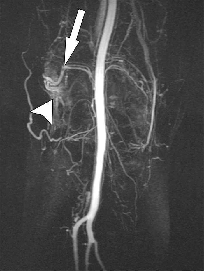
Recurrent hemarthrosis after total knee arthroplasty in a 69-year-old woman. Coronal maximum-intensity projection MR angiogram demonstrates a dominant superolateral geniculate artery (arrow) that supplies hypervascular synovium (arrowhead) as the most likely origin of recurrent intra-articular bleeding.
In a retrospective case series of 18 patients who were referred for MR angiography to evaluate recurrent hemarthrosis after failing conservative therapy or synovectomy (66), MR angiography demonstrated mild-to-marked prominence and hypertrophy of at least one artery supplying hypervascular synovium in each of 13 patients, of which nine had moderate-to-marked contrast enhancement in a specific arterial distribution. Of those nine patients, seven had no recurrent hemarthrosis after transarterial embolization. On the basis of their results, the authors proposed MR imaging with MR angiography as the initial diagnostic examination in the setting of recurrent hemarthrosis after total knee arthroplasty and unsatisfactory conservative management. MR angiographic findings of marked synovial hyperemia and dominant feeding vessel or vascular injury such as a pseudoaneurysm or arteriovenous fistula may be treated with transcatheter embolization, whereas moderate synovial hyperemia without a dominant arterial supply may be treated with surgical synovectomy. Findings of synovial impingement or frank loosening would indicate surgical revision as the most appropriate next management step. In the presence of a negative MR angiographic study and no obvious synovial impingement, observation should suffice.
Extensor Mechanism Injury
Quadriceps and patellar tendon abnormalities range from degenerative tendinosis to tendon rupture and are an important cause of complications following knee arthroplasty (23). Although tendinosis can be a pain generator, the accurate and timely diagnosis of partial and complete tears is helpful for the optimization of repair or reconstruction and for preventing joint dysfunction. Tendon rupture of the extensor mechanism may occur in isolation or in conjunction with a patellar fracture. Due to technical improvements of implant and surgical techniques, the prevalence of complete tendon ruptures today ranges around 1% (67). Patellar tendon rupture is thought to be more common than quadriceps tendon rupture.
Risk factors for tendon tears include systemic steroid use, diabetes mellitus, chronic renal insufficiency, Parkinson disease, gout, morbid obesity, multiple intra-articular steroid injections, fall, lateral retinacular release, multiple previous operations, implant design, and surgical implantation technique (68).
MR imaging is highly accurate for the evaluation of the status of the extensor tendons due to its superior soft-tissue contrast. Tendinosis is indicated by expansion of the tendon and often increased signal intensity on intermediate-weighted MR images (Fig 21). A partial tear may occur in a longitudinal or transverse direction and typically manifests as linear defects of high signal intensity on intermediate-weighted and STIR MR images. Partial thickness tears may manifest with or without retraction of the torn tendon fibers and may be associated with a peritendinous soft-tissue edema pattern in the acute stage. Full-thickness tears are characterized by the complete loss of fiber continuity (Figs 22, 23). Quadriceps muscle atrophy and fatty infiltration occur in the chronic stage of extensor tendon tears with inadequate function. In addition to the discrimination between partial and full-thickness tears, the location of a tear and the MR imaging appearance of the quality of the torn tendon can be helpful information to guide surgical management. Partial-thickness quadriceps tendon tears can be successfully repaired, whereas in full-thickness tears, excision of devitalized tissue and the use of a tendon graft may be required (68).
Figure 21.
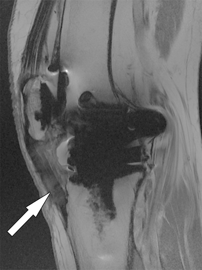
Patellar tendinosis after total knee arthroplasty in a 64-year-old woman. Sagittal intermediate-weighted fast SE image shows expansion and increased signal intensity of the patellar tendon (arrow).
Figure 22.
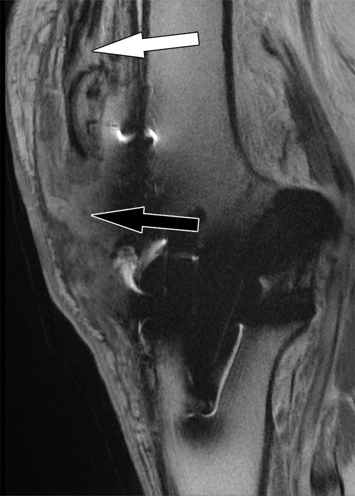
Patellar tendon rupture after total knee arthroplasty in a 78-year-old man. Sagittal intermediate-weighted fast SE image shows a full-thickness patellar tendon tear (black arrow) and patella alta. Additionally, there is a partial-thickness quadriceps tendon tear (white arrow).
Figure 23.
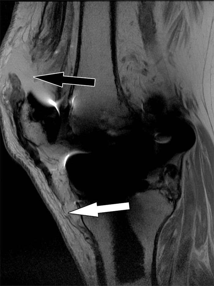
Quadriceps tendon rupture after total knee arthroplasty in a 72-year-old man. Sagittal intermediate-weighted fast SE image shows a full-thickness quadriceps tendon tear (black arrow) and patella baja. Additionally, there is a partial-thickness patellar tendon tear (white arrow).
Periprosthetic Fractures
Periarticular fractures about knee arthroplasty implants occur in 0.11%–21.4% of patients at a mean of 2–4 years after surgery (69). Patellar fractures are the most common of these, followed by supracondylar fractures, whereas tibial fractures are the least common. Periprosthetic fracture about the knee occurs most commonly in women in their 7th decade. Causes and risk factors include low-energy trauma such as falls, osteopenia and osteoporosis, use of medications, greater age, rheumatoid arthritis, neuromuscular disorders, factors of implant construction, and prior revision surgery. Defects of the anterior femoral cortex from surgical notching and cystic lesions of degenerative or rheumatoid origin, as well as osteolysis secondary to wear-related debris, are specific risk factors for femoral periprosthetic fractures. Timely diagnosis is important for preservation of joint function, fracture union, preservation of implant components without loosening, infection, and preservation of implant alignment and joint function.
MR imaging is a sensitive technique for the detection of periprosthetic fractures and can be especially valuable for the evaluation of patients with persistent clinical suspicion for a periprosthetic fracture despite negative radiographic studies. MR imaging signs of a periprosthetic fracture include a localized osseous bone marrow edema pattern, cortical thickening, periosteal reaction, and fracture lines, which may be complete or incomplete (Fig 24). The presence of these findings without a fracture line indicates an osseous stress reaction. In addition to the presence of a fracture, alignment and degree of displacement are important factors to determine if fracture reduction is indicated. As a general guide, fracture translation of less than 5 mm, angulation of less than 5°–10°, foreshortening of less than 10 mm, and rotational displacement of less than 10° may be deemed acceptable (70). Extension of the fracture into a bone-implant interface and MR imaging signs of implant loosening (component displacement and gap formation along the bone-implant interface), osteolysis, signs of polyethylene wear, and component integrity are important factors that can indicate the need for implant revision or exchange of polyethylene liners, in addition to fracture fixation. In patellar fracture, MR imaging assessment of the extensor mechanism is important, as minimally displaced fractures with an intact ligament extensor mechanism and fixed patellar component are best treated nonoperatively (Fig 25) (71).
Figure 24.
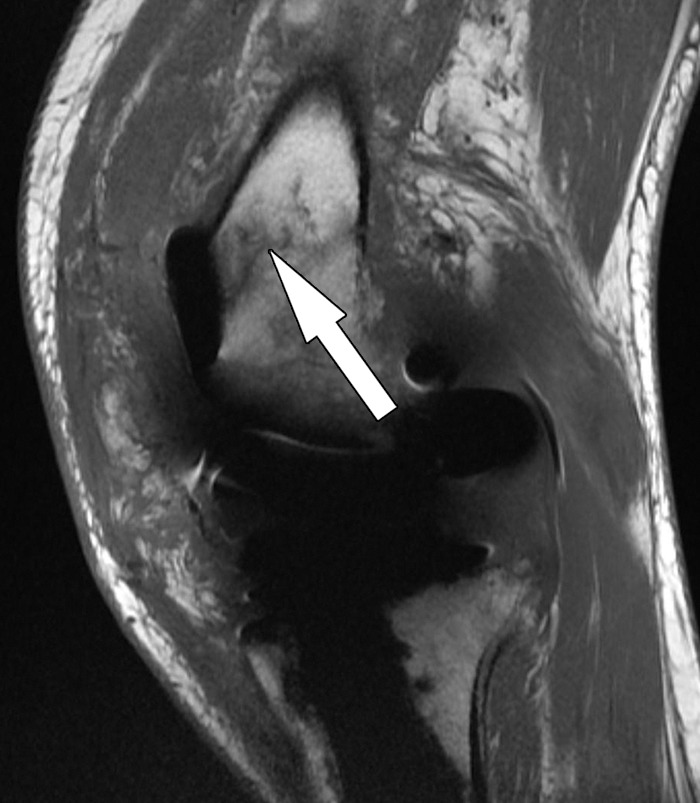
Periprosthetic supracondylar femur fracture after total knee arthroplasty in a 66-year-old man. Sagittal intermediate-weighted fast SE image shows a fracture line (arrow) in the distal femur without displacement.
Figure 25.
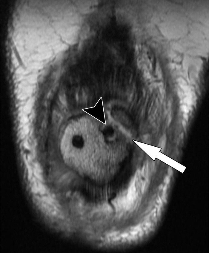
Periprosthetic patellar fracture after total knee arthroplasty in a 68-year-old woman. Coronal intermediate-weighted fast SE image shows a minimally displaced fracture (arrow) of the superolateral part of the patella. Note the bone resorption (arrowhead) around the lateral peg of the patellar component.
Conclusion
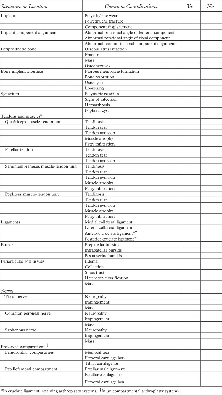
MR imaging with optimized conventional and advanced pulse sequences affords comprehensive imaging evaluation and monitoring of patients with knee arthroplasty implants. MR imaging allows for detailed evaluation of periprosthetic host bone, implant-tissue interfaces, polyethylene components, and soft tissues including synovium, tendons, ligaments, and neurovascular structures, facilitating the diagnosis and presurgical characterization of arthroplasty-related complications. MR imaging therefore contributes important information for diagnosis, prognosis, risk stratification, and surgical planning in patients with complications following knee arthroplasty.
Appendix
Figure A1.
Checklist for MR image interpretation and reporting for knee arthroplasty implants.
Presented as an education exhibit at the 2013 RSNA Annual Meeting.
For this journal-based SA-CME activity, J.F. and H.G.P. have provided disclosures (see “Disclosures of Conflicts of Interest”); all other authors, the editor, and the reviewers have disclosed no relevant relationships.
Supported by GE Healthcare.
Funding: The work was supported by the National Institute of Arthritis and Musculoskeletal and Skin Diseases (NIAMS), National Institutes of Health (NIH) (grant numbers 1R01AR064840-01, 1R01AR057343-01A2, and 1R01AR065023-01A1).
Current address: Russell H. Morgan Department of Radiology and Radiological Science, Johns Hopkins University School of Medicine, Baltimore, Md.
Disclosures of Conflicts of Interest.—: H.G.P. Activities related to the present article: disclosed no relevant relationships. Activities not related to the present article: institutional research support from GE Healthcare. Other activities: disclosed no relevant relationships. J.F. Activities related to the present article: disclosed no relevant relationships. Activities not related to the present article: grants and an honorarium from Siemens AG. Other activities: disclosed no relevant relationships.
Abbreviations:
- MAVRIC
- multiacquisition variable-resonance image combination
- PCL
- posterior cruciate ligament
- SE
- spin echo
- SEMAC
- section encoding for metal artifact correction
- STIR
- short inversion time inversion-recovery
References
- 1.Cram P, Lu X, Kates SL, Singh JA, Li Y, Wolf BR. Total knee arthroplasty volume, utilization, and outcomes among Medicare beneficiaries, 1991-2010. JAMA 2012;308(12):1227–1236. [DOI] [PMC free article] [PubMed] [Google Scholar]
- 2.Callahan CM, Drake BG, Heck DA, Dittus RS. Patient outcomes following unicompartmental or bicompartmental knee arthroplasty: a meta-analysis. J Arthroplasty 1995;10(2):141–150. [DOI] [PubMed] [Google Scholar]
- 3.Dixon MC, Brown RR, Parsch D, Scott RD. Modular fixed-bearing total knee arthroplasty with retention of the posterior cruciate ligament: a study of patients followed for a minimum of fifteen years. J Bone Joint Surg Am 2005;87(3):598–603. [DOI] [PubMed] [Google Scholar]
- 4.Ma HM, Lu YC, Ho FY, Huang CH. Long-term results of total condylar knee arthroplasty. J Arthroplasty 2005;20(5):580–584. [DOI] [PubMed] [Google Scholar]
- 5.Kurtz S, Ong K, Lau E, Mowat F, Halpern M. Projections of primary and revision hip and knee arthroplasty in the United States from 2005 to 2030. J Bone Joint Surg Am 2007;89(4):780–785. [DOI] [PubMed] [Google Scholar]
- 6.Baker PN, van der Meulen JH, Lewsey J, Gregg PJ; National Joint Registry for England and Wales; Data from the National Joint Registry for England and Wales. The role of pain and function in determining patient satisfaction after total knee replacement. J Bone Joint Surg Br 2007;89(7):893–900. [DOI] [PubMed] [Google Scholar]
- 7.Brander VA, Stulberg SD, Adams AD, et al. Predicting total knee replacement pain: a prospective, observational study. Clin Orthop Relat Res 2003;(416):27–36. [DOI] [PubMed] [Google Scholar]
- 8.Hawker G, Wright J, Coyte P, et al. Health-related quality of life after knee replacement. J Bone Joint Surg Am 1998;80(2):163–173. [DOI] [PubMed] [Google Scholar]
- 9.Mont MA, Serna FK, Krackow KA, Hungerford DS. Exploration of radiographically normal total knee replacements for unexplained pain. Clin Orthop Relat Res 1996;(331):216–220. [DOI] [PubMed] [Google Scholar]
- 10.Sofka CM, Potter HG, Figgie M, Laskin R. Magnetic resonance imaging of total knee arthroplasty. Clin Orthop Relat Res 2003;(406):129–135. [DOI] [PubMed] [Google Scholar]
- 11.Fritz J, Lurie B, Miller TT, Potter HG. MR imaging of hip arthroplasty implants. RadioGraphics 2014;34(4):E106–E132. [DOI] [PubMed] [Google Scholar]
- 12.Hargreaves BA, Worters PW, Pauly KB, Pauly JM, Koch KM, Gold GE. Metal-induced artifacts in MRI. AJR Am J Roentgenol 2011;197(3):547–555. [DOI] [PMC free article] [PubMed] [Google Scholar]
- 13.Fritz J, Lurie B, Miller TT. Imaging of hip arthroplasty. Semin Musculoskelet Radiol 2013;17(3):316–327. [DOI] [PubMed] [Google Scholar]
- 14.Schenck JF. The role of magnetic susceptibility in magnetic resonance imaging: MRI magnetic compatibility of the first and second kinds. Med Phys 1996;23(6):815–850. [DOI] [PubMed] [Google Scholar]
- 15.Lu W, Pauly KB, Gold GE, Pauly JM, Hargreaves BA. SEMAC: Slice encoding for metal artifact correction in MRI. Magn Reson Med 2009;62(1):66–76. [DOI] [PMC free article] [PubMed] [Google Scholar]
- 16.Koch KM, Lorbiecki JE, Hinks RS, King KF. A multispectral three-dimensional acquisition technique for imaging near metal implants. Magn Reson Med 2009;61(2):381–390. [DOI] [PubMed] [Google Scholar]
- 17.Sutter R, Ulbrich EJ, Jellus V, Nittka M, Pfirrmann CW. Reduction of metal artifacts in patients with total hip arthroplasty with slice-encoding metal artifact correction and view-angle tilting MR imaging. Radiology 2012;265(1):204–214. [DOI] [PubMed] [Google Scholar]
- 18.Morgan H, Battista V, Leopold SS. Constraint in primary total knee arthroplasty. J Am Acad Orthop Surg 2005;13(8):515–524. [DOI] [PubMed] [Google Scholar]
- 19.Heyse TJ, Figiel J, Hähnlein U, et al. MRI after unicondylar knee arthroplasty: the preserved compartments. Knee 2012;19(6):923–926. [DOI] [PubMed] [Google Scholar]
- 20.Heyse TJ, Figiel J, Hähnlein U, et al. MRI after patellofemoral replacement: the preserved compartments. Eur J Radiol 2012;81(9):2313–2317. [DOI] [PubMed] [Google Scholar]
- 21.Heyse TJ, Chong R, Davis J, Boettner F, Haas SB, Potter HG. MRI analysis for rotation of total knee components. Knee 2012;19(5):571–575. [DOI] [PubMed] [Google Scholar]
- 22.Raphael B, Haims AH, Wu JS, Katz LD, White LM, Lynch K. MRI comparison of periprosthetic structures around zirconium knee prostheses and cobalt chrome prostheses. AJR Am J Roentgenol 2006;186(6):1771–1777. [DOI] [PubMed] [Google Scholar]
- 23.Sharkey PF, Hozack WJ, Rothman RH, Shastri S, Jacoby SM. Why are total knee arthroplasties failing today? Clin Orthop Relat Res 2002;(404):7–13. [DOI] [PubMed] [Google Scholar]
- 24.Windsor RE, Scuderi GR, Moran MC, Insall JN. Mechanisms of failure of the femoral and tibial components in total knee arthroplasty. Clin Orthop Relat Res 1989;(248):15–19; discussion 19–20. [DOI] [PubMed] [Google Scholar]
- 25.Goldring SR, Schiller AL, Roelke M, Rourke CM, O’Neil DA, Harris WH. The synovial-like membrane at the bone-cement interface in loose total hip replacements and its proposed role in bone lysis. J Bone Joint Surg Am 1983;65(5):575–584. [PubMed] [Google Scholar]
- 26.Cook SD, Thomas KA, Haddad RJ, Jr. Histologic analysis of retrieved human porous-coated total joint components. Clin Orthop Relat Res 1988;(234):90–101. [PubMed] [Google Scholar]
- 27.Naudie DD, Ammeen DJ, Engh GA, Rorabeck CH. Wear and osteolysis around total knee arthroplasty. J Am Acad Orthop Surg 2007;15(1):53–64. [DOI] [PubMed] [Google Scholar]
- 28.Collier JP, Mayor MB, McNamara JL, Surprenant VA, Jensen RE. Analysis of the failure of 122 polyethylene inserts from uncemented tibial knee components. Clin Orthop Relat Res 1991;(273):232–242. [PubMed] [Google Scholar]
- 29.Purdue PE, Koulouvaris P, Potter HG, Nestor BJ, Sculco TP. The cellular and molecular biology of periprosthetic osteolysis. Clin Orthop Relat Res 2007;454:251–261. [DOI] [PubMed] [Google Scholar]
- 30.Peters PC, Jr, Engh GA, Dwyer KA, Vinh TN. Osteolysis after total knee arthroplasty without cement. J Bone Joint Surg Am 1992;74(6):864–876. [PubMed] [Google Scholar]
- 31.Carlsson AS, Gentz CF. Radiographic versus clinical loosening of the acetabular component in noninfected total hip arthroplasty. Clin Orthop Relat Res 1984;(185):145–150. [PubMed] [Google Scholar]
- 32.Robertson DD, Sutherland CJ, Lopes T, Yuan J. Preoperative description of severe acetabular defects caused by failed total hip replacement. J Comput Assist Tomogr 1998;22(3):444–449. [DOI] [PubMed] [Google Scholar]
- 33.Claus AM, Totterman SM, Sychterz CJ, Tamez-Peña JG, Looney RJ, Engh CA, Sr. Computed tomography to assess pelvic lysis after total hip replacement. Clin Orthop Relat Res 2004;(422):167–174. [DOI] [PubMed] [Google Scholar]
- 34.Malchau H, Potter HG; Implant Wear Symposium 2007 Clinical Work Group. How are wear-related problems diagnosed and what forms of surveillance are necessary? J Am Acad Orthop Surg 2008;16(suppl 1):S14–S19. [DOI] [PubMed] [Google Scholar]
- 35.Potter HG, Foo LF. Magnetic resonance imaging of joint arthroplasty. Orthop Clin North Am 2006;37(3):361–373, vi–vii. [DOI] [PubMed] [Google Scholar]
- 36.Walde TA, Weiland DE, Leung SB, et al. Comparison of CT, MRI, and radiographs in assessing pelvic osteolysis: a cadaveric study. Clin Orthop Relat Res 2005;(437):138–144. [DOI] [PubMed] [Google Scholar]
- 37.Weiland DE, Walde TA, Leung SB, et al. Magnetic resonance imaging in the evaluation of periprosthetic acetabular osteolysis: a cadaveric study. J Orthop Res 2005;23(4):713–719. [DOI] [PubMed] [Google Scholar]
- 38.Gonzalez MH, Mekhail AO. The failed total knee arthroplasty: evaluation and etiology. J Am Acad Orthop Surg 2004;12(6):436–446. [DOI] [PubMed] [Google Scholar]
- 39.Fehring TK, Valadie AL. Knee instability after total knee arthroplasty. Clin Orthop Relat Res 1994;(299):157–162. [PubMed] [Google Scholar]
- 40.Montgomery RL, Goodman SB, Csongradi J. Late rupture of the posterior cruciate ligament after total knee replacement. Iowa Orthop J 1993;13:167–170. [PMC free article] [PubMed] [Google Scholar]
- 41.Bozic KJ, Ries MD. The impact of infection after total hip arthroplasty on hospital and surgeon resource utilization. J Bone Joint Surg Am 2005;87(8):1746–1751. [DOI] [PubMed] [Google Scholar]
- 42.Kurtz SM, Lau E, Schmier J, Ong KL, Zhao K, Parvizi J. Infection burden for hip and knee arthroplasty in the United States. J Arthroplasty 2008;23(7):984–991. [DOI] [PubMed] [Google Scholar]
- 43.Trampuz A, Zimmerli W. New strategies for the treatment of infections associated with prosthetic joints. Curr Opin Investig Drugs 2005;6(2):185–190. [PubMed] [Google Scholar]
- 44.Wilson MG, Kelley K, Thornhill TS. Infection as a complication of total knee-replacement arthroplasty: risk factors and treatment in sixty-seven cases. J Bone Joint Surg Am 1990;72(6):878–883. [PubMed] [Google Scholar]
- 45.Segawa H, Tsukayama DT, Kyle RF, Becker DA, Gustilo RB. Infection after total knee arthroplasty: a retrospective study of the treatment of eighty-one infections. J Bone Joint Surg Am 1999;81(10):1434–1445. [DOI] [PubMed] [Google Scholar]
- 46.Plodkowski AJ, Hayter CL, Miller TT, Nguyen JT, Potter HG. Lamellated hyperintense synovitis: potential MR imaging sign of an infected knee arthroplasty. Radiology 2013;266(1):256–260. [DOI] [PubMed] [Google Scholar]
- 47.Hayter CL, Koff MF, Potter HG. Magnetic resonance imaging of the postoperative hip. J Magn Reson Imaging 2012;35(5):1013–1025. [DOI] [PubMed] [Google Scholar]
- 48.Parvizi J, Zmistowski B, Berbari EF, et al. New definition for periprosthetic joint infection: from the Workgroup of the Musculoskeletal Infection Society. Clin Orthop Relat Res 2011;469(11):2992–2994. [DOI] [PMC free article] [PubMed] [Google Scholar]
- 49.White J, Kelly M, Dunsmuir R. C-reactive protein level after total hip and total knee replacement. J Bone Joint Surg Br 1998;80(5):909–911. [DOI] [PubMed] [Google Scholar]
- 50.Della Valle C, Parvizi J, Bauer TW, et al. American Academy of Orthopaedic Surgeons clinical practice guideline on: the diagnosis of periprosthetic joint infections of the hip and knee. J Bone Joint Surg Am 2011;93(14):1355–1357. [DOI] [PubMed] [Google Scholar]
- 51.Barrack RL, Schrader T, Bertot AJ, Wolfe MW, Myers L. Component rotation and anterior knee pain after total knee arthroplasty. Clin Orthop Relat Res 2001;(392):46–55. [DOI] [PubMed] [Google Scholar]
- 52.Murakami AM, Hash TW, Hepinstall MS, Lyman S, Nestor BJ, Potter HG. MRI evaluation of rotational alignment and synovitis in patients with pain after total knee replacement. J Bone Joint Surg Br 2012;94(9):1209–1215. [DOI] [PubMed] [Google Scholar]
- 53.Nicoll D, Rowley DI. Internal rotational error of the tibial component is a major cause of pain after total knee replacement. J Bone Joint Surg Br 2010;92(9):1238–1244. [DOI] [PubMed] [Google Scholar]
- 54.Heyse TJ, Figiel J, Hähnlein U, et al. MRI after unicondylar knee arthroplasty: rotational alignment of components. Arch Orthop Trauma Surg 2013;133(11):1579–1586. [DOI] [PubMed] [Google Scholar]
- 55.Uehara K, Kadoya Y, Kobayashi A, Ohashi H, Yamano Y. Bone anatomy and rotational alignment in total knee arthroplasty. Clin Orthop Relat Res 2002;(402):196–201. [DOI] [PubMed] [Google Scholar]
- 56.Yoshino N, Takai S, Ohtsuki Y, Hirasawa Y. Computed tomography measurement of the surgical and clinical transepicondylar axis of the distal femur in osteoarthritic knees. J Arthroplasty 2001;16(4):493–497. [DOI] [PubMed] [Google Scholar]
- 57.Bong MR, Di Cesare PE. Stiffness after total knee arthroplasty. J Am Acad Orthop Surg 2004;12(3):164–171. [DOI] [PubMed] [Google Scholar]
- 58.Kurosaka M, Yoshiya S, Mizuno K, Yamamoto T. Maximizing flexion after total knee arthroplasty: the need and the pitfalls. J Arthroplasty 2002;17(4 suppl 1):59–62. [DOI] [PubMed] [Google Scholar]
- 59.Lucas TS, DeLuca PF, Nazarian DG, Bartolozzi AR, Booth RE, Jr. Arthroscopic treatment of patellar clunk. Clin Orthop Relat Res 1999;(367):226–229. [PubMed] [Google Scholar]
- 60.Beight JL, Yao B, Hozack WJ, Hearn SL, Booth RE, Jr. The patellar “clunk” syndrome after posterior stabilized total knee arthroplasty. Clin Orthop Relat Res 1994;(299):139–142. [PubMed] [Google Scholar]
- 61.Heyse TJ, Chong R, Davis J, Haas SB, Figgie MP, Potter HG. MRI diagnosis of patellar clunk syndrome following total knee arthroplasty. HSS J 2012;8(2):92–95. [DOI] [PMC free article] [PubMed] [Google Scholar]
- 62.Vernace JV, Rothman RH, Booth RE, Jr, Balderston RA. Arthroscopic management of the patellar clunk syndrome following posterior stabilized total knee arthroplasty. J Arthroplasty 1989;4(2):179–182. [DOI] [PubMed] [Google Scholar]
- 63.Kindsfater K, Scott R. Recurrent hemarthrosis after total knee arthroplasty. J Arthroplasty 1995;10(suppl):S52–S55. [DOI] [PubMed] [Google Scholar]
- 64.Saksena J, Platts AD, Dowd GS. Recurrent haemarthrosis following total knee replacement. Knee 2010;17(1):7–14. [DOI] [PubMed] [Google Scholar]
- 65.Ohdera T, Tokunaga M, Hiroshima S, Yoshimoto E, Matsuda S. Recurrent hemarthrosis after knee joint arthroplasty: etiology and treatment. J Arthroplasty 2004;19(2):157–161. [DOI] [PubMed] [Google Scholar]
- 66.Hash TW, 2nd, Maderazo AB, Haas SB, Saboeiro GR, Trost DW, Potter HG. Magnetic resonance angiography in the management of recurrent hemarthrosis after total knee arthroplasty. J Arthroplasty 2011;26(8):1357–1361, e1. [DOI] [PubMed] [Google Scholar]
- 67.Parker DA, Dunbar MJ, Rorabeck CH. Extensor mechanism failure associated with total knee arthroplasty: prevention and management. J Am Acad Orthop Surg 2003;11(4):238–247. [DOI] [PubMed] [Google Scholar]
- 68.Pagnano MW. Patellar tendon and quadriceps tendon tears after total knee arthroplasty. J Knee Surg 2003;16(4): 242–247. [PubMed] [Google Scholar]
- 69.Chmell MJ, Moran MC, Scott RD. Periarticular fractures after total knee arthroplasty: principles of management. J Am Acad Orthop Surg 1996;4(2):109–116. [DOI] [PubMed] [Google Scholar]
- 70.Schatzker J, Lambert DC. Supracondylar fractures of the femur. Clin Orthop Relat Res 1979;(138):77–83. [PubMed] [Google Scholar]
- 71.Sheth NP, Pedowitz DI, Lonner JH. Periprosthetic patellar fractures. J Bone Joint Surg Am 2007;89(10):2285–2296. [DOI] [PubMed] [Google Scholar]


