Abstract
Inspired by the impulsive movements in plants, this research investigates the physics of a novel fluidic origami concept for its pressure-dependent multi-stability. In this innovation, fluid-filled tubular cells are synthesized by integrating different Miura-Ori sheets into a three-dimensional topological system, where the internal pressures are strategically controlled similar to the motor cells in plants. Fluidic origami incorporates two crucial physiological features observed in nature: one is distributed, pressurized cellular organization, and the other is embedded multi-stability. For a single fluidic origami cell, two stable folding configurations can coexist due to the nonlinear relationships among folding, crease material deformation and internal volume change. When multiple origami cells are integrated, additional multi-stability characteristics could occur via the interactions between pressurized cells. Changes in the fluid pressure can tailor the existence and shapes of these stable folding configurations. As a result, fluidic origami can switch between being mono-stable, bistable and multi-stable with pressure control, and provide a rapid ‘snap-through’ type of shape change based on the similar principles as in plants. The outcomes of this research could lead to the development of new adaptive materials or structures, and provide insights for future plant physiology studies at the cellular level.
Keywords: rapid nastic plant movement, cellular structure, fluidic origami, multi-stability, morphing, Venus flytrap
1. Introduction
Plants can move without muscles, and some of them are capable of achieving spectacularly fast movements and then recovering to original configurations [1,2]. A well-known example is the carnivorous Venus flytrap (Dionaea muscipula), which can snap close its trap lobes within a second to capture the insect prey for nutrition intake [3–6] (figure 1a). The rapidity and force of its movement inspired Charles Darwin so much that he remarked on it as ‘one of the most wonderful in the world’ [7]. Other examples include bladderworts (Utricularia spp.) [8] and possibly triggerplants (Stylidium) [9]. Despite the wide physiological differences among these species, their rapid movements are all initiated by strategically swelling or shrinking cells (motor cells) at different locations by ion transport and associated osmotic fluid flow [10] (figure 1b). These distributed and pressurized motor cells provide both nastic movements and structural rigidity, without the distinction between the ‘actuators’ and ‘structures’ that are commonly seen separated in the more conventional active structures; as a result, the active plant organs can output large actuation force and stroke with a superior power to density ratio [11]. Osmosis alone, however, is a relatively slow process, restricted by the filtration coefficients of the plant cell plasma membrane. There are physiological evidences suggesting that some plants may have evolved to exploit the buckling mechanisms in multi-stable systems to significantly amplify the movement speed and amplitude [12] (figure 1c). In the case of Venus flytrap, the initial osmotic cell deformation would slowly bring the trap lobes to a critical shape where they become elastically unstable, and then the buckling takes over and ‘snaps’ the lobes rapidly to the desired final shape [3,5]. This snap-through mechanism enables the plants to move at least an order of magnitude faster than osmosis alone [12], and in some cases even faster than human visual perception [8]. Therefore, the distributed, fluidic cellular organization and the embedded multi-stability are two important physiological features for the impulsive plant movements; and applying both of them to engineered structures and material designs could enable unprecedented rapid shape change capability with advantageous weight efficiency.
Figure 1.
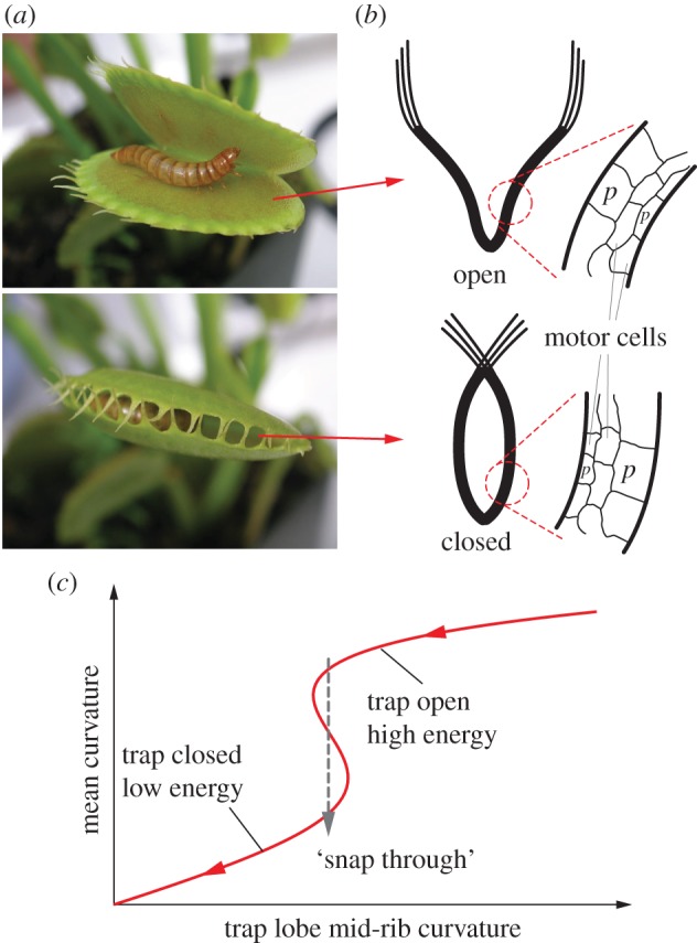
The impulsive movements of the trap lobes of Venus flytrap (a) involve two physiological features that are closely relevant for developing engineered adaptive structures. (b) Distributed and pressurized cellular organization that can lead to large actuation force and stroke with a superior power to density ratio. (c) Embedded bistability that can amplify the response speed (adapted from Forterre et al. [3]). Flytrap photo credit: Beatrice Murch (www.wikipedia.com). (Online version in colour.)
Various plant-inspired material and structure concepts were proposed to exploit the cellular organization feature for effective shape changes [13–18]. The ‘cells’ in these concepts took various shapes, including cylindrical capsules, customized polygons, topologically optimized geometries and fibre composite tubes. A large number of these cells can form a structure so that when some of them are pressurized their internal volume would increase to initiate a prescribed global shape change. On the other hand, several systems were proposed to use multi-stability for rapid actuation; they incorporated pre-stressed sheets with double curvatures similar to the trap lobes of Venus flytrap [19–21]. However, none of these works have explored and developed rigorous understanding on how to integrate these two features together in a synergistic way to holistically manifest the attractive characteristics of impulsive plant movements.
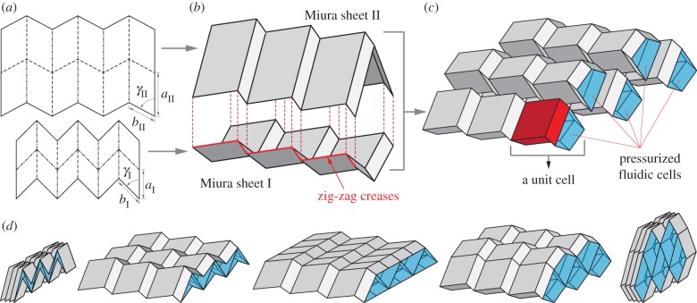
To advance the state of the art, in this research, a novel fluidic origami concept is created by merging these two features of plant movements with the rich designs in paper folding art. Building upon the concept of stacking Miura-Ori sheets into a three-dimensional topology with naturally embedded tubular cells [22,23], the new idea is to strategically control the cell internal pressures with working fluid to achieve shape change similar to the shrinking and swelling of the motor cells in nastic plant movements (figure 2). Such fluidic origami can achieve significant actuation/morphing by actively changing the internal fluid volume, and stiffness tuning by constraining the fluid volume [24].
Figure 2.
The concept of fluidic origami. (a,b) Two compatible Miura-Ori sheets, where the dashed lines are mountain fold creases and dashed-dotted lines are valley fold creases, can be connected along their zig-zag creases to form an origami cell. (c) Different fluid-filled origami cells can then be integrated into a three-dimensional topology, where the most basic unit cell is highlighted. (d) Shape morphing (folding) can be achieved by controlling the fluidic pressures and volumes. (Online version in colour.)
This research, for the first time, thoroughly investigates the elastic characteristics of the fluidic origami system together with the effects of internal pressure to reveal a very intriguing feature of fluidic origami: pressure-dependent multi-stability. Various multi-stability mechanisms in origami-based systems were explored previously [25–30], but the pressure-dependent multi-stability discussed in this research is uniquely different in several aspects. It originates from the combination of two different physical principles: origami elastically induced and fluidic pressure induced multi-stability. For a single fluidic origami cell, two stable folding configurations could coexist due to the nonlinear relationships among folding, crease material deformation and enclosed fluid volume change. When multiple fluidic origami cells are integrated together, additional multi-stability characteristics could occur via the interaction between pressurized cells. The existence and shape of these stable folding configurations can be tailored by internal pressure control, so that when the pressure reaches some specific critical levels, the fluidic origami can switch between being mono-stable, bistable and even multi-stable. Such rich and surprising pressure–stability relationship enables the fluidic origami to achieve rapid and distributed shape change with similar principles to those that govern rapid plant movements. In addition, the multi-stability mechanism depends primarily on scale-independent geometric principles, and thus fluidic origami can be fabricated at vastly different sizes without losing the rich pressure-dependent multi-stability characteristics. Therefore, the proposed concept could have great potential in the development of multi-functional materials and structures at different size scales.
The objective of this research is to extensively investigate the physical principles of and provide insights into the fluidic origami pressure-dependent multi-stability. The following sections discuss the geometry and kinematics of the fluidic origami, analyse the physical origins behind the pressure–stability relationships, correlate the system characteristics to origami designs, discuss the potential functions of the fluidic origami based structural and material systems and suggest several lessons learned from this study that can be applied to physiology studies on impulsive plant movements at the cellular level.
2. Design and kinematics
The backbone of the fluidic origami is a set of kinematically compatible tubular cells made by connecting two different Miura-Ori folded sheets together (figure 2). Miura-Ori crease is rigid-foldable so it can retain a degree of freedom for folding even if the facets are assumed rigid and the creases are treated as hinges; it is also a periodic tessellation, so one can focus on the most fundamental unit cells (figure 3a) to analyse the overall kinematics (a tubular fluidic origami cell is essentially a series of identical unit cells). Miura-Ori can be designed by three constants that remain unchanged regardless of folding: the lengths of two adjacent crease lines (ak and bk), and the angle between these two (γk) (figure 2a). The folding motion can be described by the dihedral folding angle (θk) defined between the x–y reference plane and its facets (figure 3a). The subscript k (=I,II) indicates the two different Miura sheets. Without loss of generality, the Miura with the shorter crease length (a) is designated as sheet I. To make the two connected Miura-Ori sheets kinematically compatible so that they will not separate during folding, the following relations need to be satisfied [23]:
| 2.1 |
and
| 2.2 |
Figure 3.
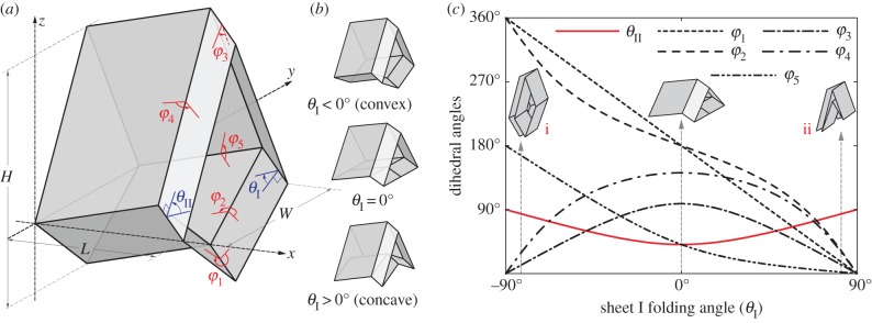
The geometry and kinematics of the unit cell. (a) Definition of the various geometric variables;  and
and  are dihedral angles defined between the facets and x–y reference plane. (b) The smaller Miura sheet I can bulge out or nest in the bigger sheet II. (c) The values of different dihedral angles defined in this unit cell with respect to
  . Between configurations (i) and (ii) in (c), the folding angles of sheet I have the same magnitude but opposite sign; but the folding angles are the same for sheet II. (Online version in colour.)
The folding angles of the two Miura-Ori sheets are not independent and they obey the following relationship [23]:
| 2.3 |
 ranges from −π/2 to π/2 so that sheet I bulges out of the larger sheet (II) when
  and nests in otherwise (figure 3b). For clarity, folding configuration with
  is referred as the ‘convex shape’ and otherwise ‘concave shape’. Previous studies pointed out that the dominant deformation modes of an individual Miura-Ori sheet could be bending and twisting rather than folding due the facet flexibility [23]. However, once multiple Miura are connected, the bending and twisting are effectively suppressed, leaving folding as the primary deformation mode (proof in electronic supplementary material, appendix S1). Therefore, the kinematic and elastic characteristics of a fluidic origami unit cell can be calculated with respect to one independent folding variable. In this study, the sheet I folding angle
  is chosen for such purpose so the unit cell length, width and height can be calculated as follows:
| 2.4 |
| 2.5 |
and
| 2.6 |
The enclosed internal fluid volume is
 |
2.7 |
The dihedral angles between adjacent facets as defined in figure 3a are
 |
2.8 |
| 2.9 |
and  ,
,  ,
,  . The values of these dihedral angles (
 ) and sheet II folding angle (
 ) with respect to
  are illustrated in figure 3c. Unless noted otherwise, the case studies in this paper are based on a sample Miura-Ori design listed in table 1. Note that for one
  angle, there exist two corresponding
  angles of the same magnitude but opposite signs (one with concave shape and the other convex). The only exception is the minimum possible value of
  which corresponds to only one
  angle of 0° (flat Miura sheet I). This non-unique relationship between sheets I and II folding angles is the origin of the elastic bistability discussed in the following section.
Table 1.
Design parameters used in the case studies.
| Miura-Ori design parameters | aI = 25 mm | b = 25 mm |
| aII = 1.25aI | γI = 60° | |
| crease torsional stiffness | kI = 5 N | kc = kI |
3. Elastic bistability of an unpressurized cell
Since fluidic origami is rigid-foldable with suppressed bending and twisting, its facet material can be assumed rigid. This assumption is sufficient to analyse the underlying physical principles of the pressure-dependent stability characteristics. The creases are assumed as thin flexural hinges so that one can assign kI and kII as the torsional spring stiffness per unit length for the creases of sheet I and II, respectively; and kc as the spring stiffness per unit length of the zig-zag creases that connect the two sheets. The total torsional spring constants (Ki) corresponding to the dihedral angles ( ) defined in figure 3a are:


 and
and  The numerical constants in these equations equal the number of creases that have the same dihedral angle in a unit cell. The total spring potential energy of the system is
 |
3.1 |
where  are the dihedral angles corresponding to the stress-free stable folding configuration (
 ) where no creases are subject to deformation. The change in
  with respect to the change in folding angle (
 ) is illustrated in figure 4. Because of the nonlinear geometric correlations between folding and crease deformation, the effective origami stiffness is highly nonlinear with respect to the folding angle even though the constituent crease material is linearly elastic. The double potential energy wells, which are the defining characteristics of a bistable system, start to show up as the torsional spring stiffness of sheet II (kII) becomes sufficiently larger than kI and kc (figure 4a), or the stress-free folding angle (
 ) deviates further away from 0° (figure 4b). The origin of this elastic bistability is directly related to the non-unique
  relationship as illustrated in figure 3c. If the stress-free stable folding configuration is designed to have a concave shape, the bistable one will be convex; and vice versa. Therefore, even the Miura sheet I is deformed significantly between the two stable configurations; the stiffer sheet II is not deformed much.
Figure 4.
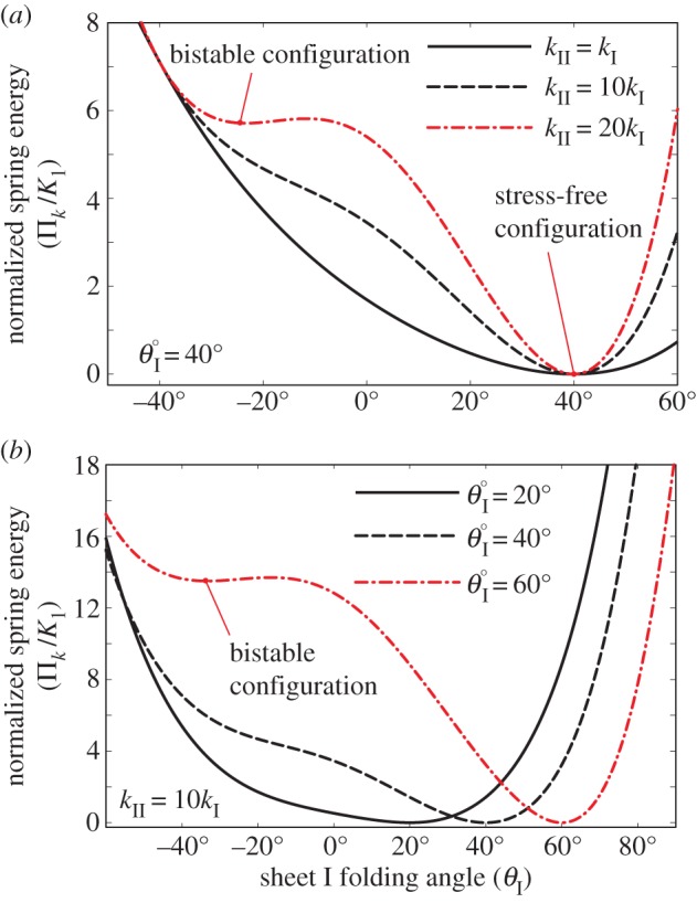
The normalized spring energy landscape with respect to origami folding. The bistable characteristics shown in the dashed dotted lines become prominent if kII/kI ratio is high (a) or the stress-free resting folding angle deviates further away from 0° (b). Here, the stress-free configuration is defined as the stable folding shape where no creases are subject to deformation (hence zero potential energy); the bistable configuration is defined as the stable folding shape with some crease deformations. (Online version in colour.)
To fabricate a proof-of-concept prototype of the elastically bistable origami cell, the facets are water jet cut individually from 0.01-inch thick stainless steel sheets. Then they are applied to an adhesive, 0.05-inch thick plastic film (ultra-high-molecular-weight polyethylene) to form two complete Miura-Ori sheets (figure 5a). This particular prototype has a Miura-Ori design of 
 and
and  Bended spring steel tapes are bonded to creases corresponding to the dihedral angle
  to provide some torsional stiffness (K4). The stress-free resting angle for these tape springs is about 90°, which corresponds to
  Then the two Miura strips are connected along their zig-zag creases by adhesive films to form a complete fluidic origami cell. Since the torsional stiffness from the adhesive film itself is negligible, the crease torsional stiffness K4 in sheet II is significantly larger than other crease stiffness in sheet I. As a result, the fluidic origami cell becomes stable at two configurations, one concave and one convex (figure 5b).
Figure 5.
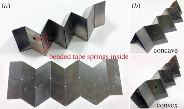
Experimental demonstration of elastically induced bistability. (a) Miura-Ori sheets made by bonding stiff facets onto an adhesive plastic film. (b) The two stable configurations. (Online version in colour.)
The potential energy landscapes in figure 4 are calculated with respect to the folding angle  If the same energy is plotted with respect to the external geometries of fluidic origami (L, H, W in equations (2.4)–(2.6)), it shows quite unique characteristics along different principal orientations (figure 6). Along the z-axis, the fluidic origami is stable at two different heights, and the critical, unstable equilibrium (energy ridge) is located between these two (figure 6a); however, along the x- and y-axes, the two stable lengths or widths are located on the same side of the unstable equilibrium (figure 6b,c). Therefore, if the fluidic origami is subjected to sufficiently large external forces along the z-axis, it can be ‘snapped’ between the two stable heights. If the fluidic origami is subject to forces along x- or y-axis only, it can only be snapped from the higher-energy stable configuration to the low-energy one, but not vice versa. Moreover, the unstable equilibrium can be very close to the maximum possible length or width that correspond to
  thus fluidic origami can appear to be almost mono-stable, around either of the stable configurations, within most of its deformation range along x- and y-axes.
Figure 6.
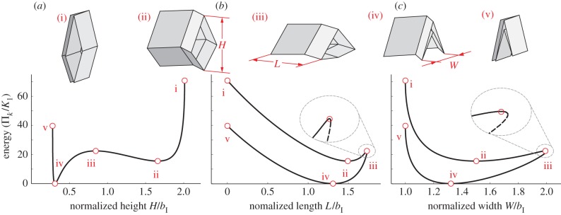
The energy landscapes of a bistable origami with respect to external geometry in different orientations. kII/kI = 20 and  Different types of the folding configurations are highlighted: (i) and (v) fully folded; (ii) and (iv) the two stable configurations; (iii) the critical, unstable equilibrium configurations. (Online version in colour.)
4. Pressure–stability relationship of a pressurized cell
The bistable characteristics of the fluidic origami cell can be tailored by internal pressurization via pumping. Given that the mechanical work done by the pressure is conservative, the potential energy from the pressure in an individual unit cell is
| 4.1 |
where enclosed volume V is a function of folding as defined in equation (2.7), and fluid pressure P is determined by external pumping. Vm is the maximum possible internal volume, and this term is introduced to set the zero potential of  at this particular configuration. The magnitude of Vm is determined only by Miura design:
| 4.2 |
which corresponds to a folding angle  given by
 |
4.3 |
The total system energy is the summation of  in (3.1) and
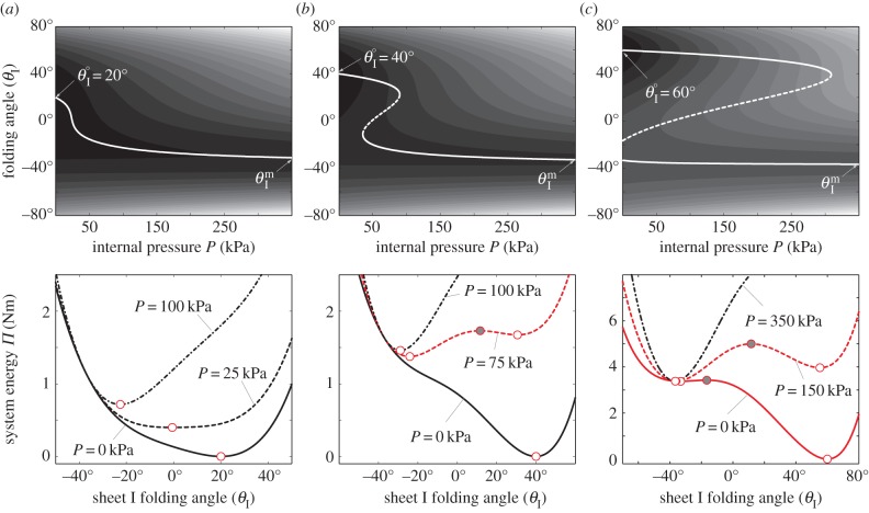
  in (4.1); therefore, the stability characteristics of a fluidic origami cell become a function of internal fluid pressure, and this relationship is surprisingly rich: even with the same Miura-Ori crease, different assignments of the kII/kI ratio and folding angle
  value can lead to three distinctive types of pressure–stability relationships.
(i) The fluidic origami is always mono-stable, and the value of the stable folding angle can be tailored significantly by internal pressure. At low pressure, fluidic origami is stable near
 ; as pressure increases, the stable folding angle converges to
  (figure 7a).
(ii) The fluidic origami is initially mono-stable near
 However, as the internal pressure rises above a critical level, a second branch of stable configurations shows up near
  so that the system becomes bistable. When the pressure continues to rise and exceeds a second critical level, the stable branch near
  disappears so that fluidic origami becomes mono-stable again (figure 7b). This type of pressure–stability relationship will be referred to as ‘weakly bistable’.
(iii) The fluidic origami is initially bistable as shown in the previous section. As the internal pressure rises above a critical level, one of the stable equilibrium branches disappears and the system becomes mono-stable near
 (figure 7c). This type of pressure–stability relationship will be referred to as ‘strongly bistable’.
Figure 7.
Pressure–stability relationships in the single fluidic origami cell. kII/kI = 10 and the stress-free stable folding angles  are different: (a) 20°, (b) 40° and (c) 60°.
  is approximately −37° for all of these cases. Plots in the first row are the energy terrains, where the solid curves are stable folding configurations (energy valley), and dashed curves are the critical unstable configurations (energy ridge). The grey gradient represents the levels of system energy (Π): the lighter the colour, the higher the energy. Plots in the second row are the corresponding energy landscapes at some pressure levels, where the hollow circles are stable configurations and solid circles are unstable. (Online version in colour.)
The proof-of-concept fluidic origami prototype discussed in the previous section is strongly bistable by design. To experimentally demonstrate its pressure–stability relationship, a custom-made plastic film bladder is inserted into the origami cell to provide a pneumatic pressurization (measured by a PCB™ 113B21 pressure transducer), and the origami deformation in the height direction is measured by a laser vibrometer (Polytech™ OFV 303) (figure 8a). The fluidic origami cell is initially placed at the stable equilibrium branch further away from  (concave shape). As the internal pressure rises above the critical level, the fluidic origami cell becomes mono-stable so it is forced to ‘snap’ to the other stable branch of convex shape by releasing some of the stored energy, leading to a rapid shape change (figure 8b; electronic supplementary material, movie S1).
Figure 8.
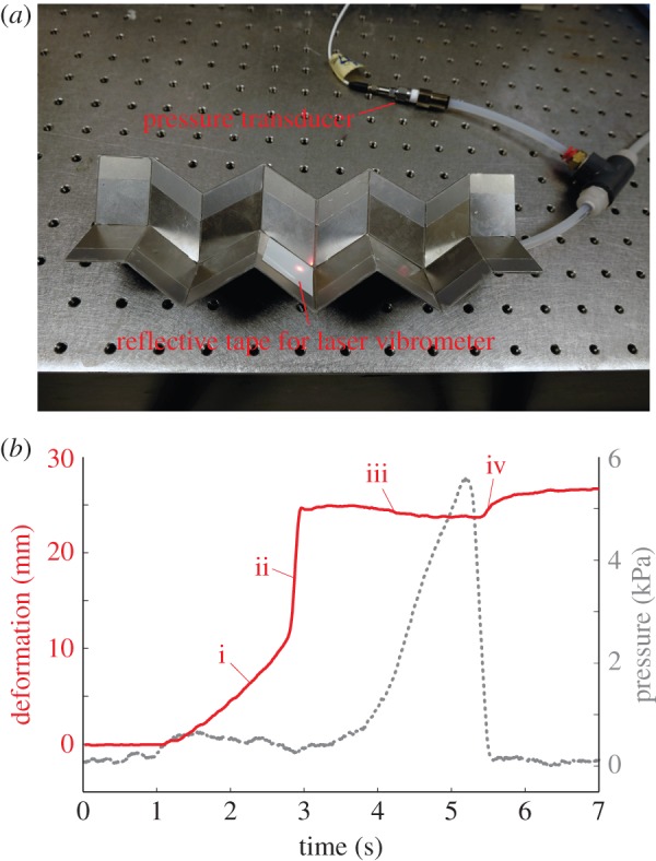
Experimental demonstration on the pressure–stability relationship in a strongly bistable design. (a) Experimental set-up. (b) The deformation in origami height (solid line) and pressure (dashed line) measurements. The origami deformation can be divided into four stages: (i) initial pressurization and slow deformation, the origami staying on the branch of stable concave configurations; (ii) snap-through rapid deformation and shift to the branch of convex configurations (pressure actually drops slightly because of the imperfect contact between bladder and origami); (iii) pressure continues to rise, and origami converges to the  configuration (mono-stable at this stage); (iv) pressure released, and origami remains on the branch of stable convex configurations. Interested readers can refer to the electronic supplementary material, movie S1, for a direct visualization of the pressure–stability relationship. (Online version in colour.)
Figure 9 illustrates the existence of these three types of pressure–stability relationships with respect to different kII/kI and  assignments, as well as to different Miura-Ori designs. Generally speaking, the values of
  folding angles need to deviate away from zero for bistability to occur; and the higher kII/kI ratio, the easier it is to achieve bistability. Strongly bistable designs occur with both positive and negative
  values; however, the weak bistability only exists when
  is positive. Different Miura-Ori designs can also affect the pressure–stability relationship. Bistable designs are easier to achieve with a lower aII/aI ratio by comparing the four different design space plots in figure 9. The results in this figure indicate that different fluidic origami can exhibit similar pressure–stability relationships even if they differ from each other significantly in terms of external geometries and folding motion ranges. And the design space in figure 9 could provide a practical guideline to customize fluidic origami for various application requirements.
Figure 9.
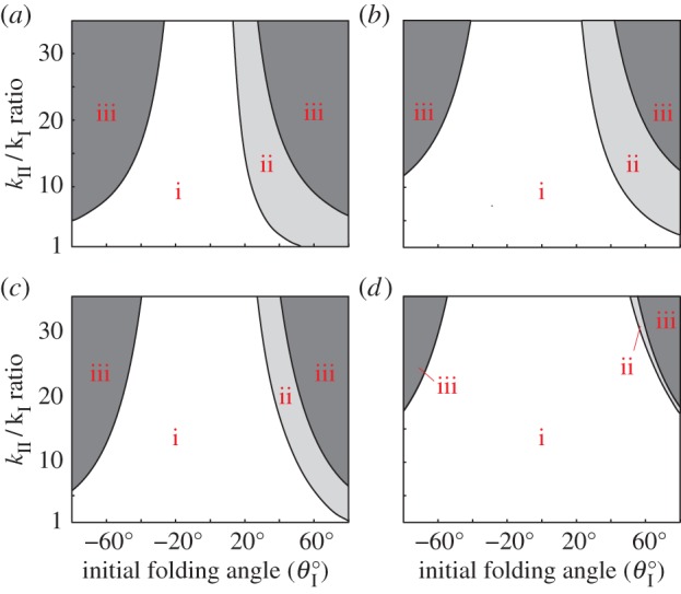
Pressure–stability relationship with respect to different fluidic origami designs. The white region corresponds to mono-stable designs, the light grey region is weakly bistable designs and the dark grey region is strongly bistable designs. The Miura-Ori are different in these four cases: (a) aII = 1.25aI, γI = 60°, (b) aII = 1.25aI, γI = 30°, (c) aII = 2aI, γI = 60° and (d) aII = 2aI, γI = 30°. b = aI for all four cases. (Online version in colour.)
5. Multi-stability from the interaction of two pressurized cells
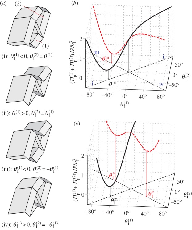
A single fluidic origami cell can be switched between being mono- and bi-stable by internal pressure control, and additional stable folding configurations could occur via the interactions between pressurized cells. For a clear explanation without losing generality, here we will focus on a pair of identical fluidic origami unit cells, denoted as cell (1) and (2), that are stacked together into a dual-cell assembly as shown in figure 10a. The sheet I folding angles of these two cells ( ) can either be equal to each other so that they are both concave or both convex (‘primary folding branch’); or
  can have the same magnitude but opposite signs so that one is concave and the other convex (‘secondary folding branch’). These two folding branches are connected where the Miura sheets I are both flat:
  Because of these kinematic constraints, the total energy of the assembly is simply the summation of the energies from two cells (
 ). This paper considers two representative pressure loading scenarios: ‘uniform pressure’ by which the two cells have the same internal pressure and ‘differential pressure’ by which only one cell is pressurized.
Figure 10.
The pressure potential energy landscape of two identical fluidic origami cells. (a) Different folding angle combinations, where (i) and (ii) are the parts of the primary folding branch, (iii) and (iv) are secondary. (b) Differential pressure, where cell (1) is pressurized. (c) Uniform pressure. Solid curve is the primary folding branch and dashed curve is the secondary folding branch. In this specific plot: aII = 1.1, aI = 1.1b and γI = 75°. (Online version in colour.)
Additional stable folding configurations can occur due to the interaction between the two pressurized cells, and the origins of these pressure-induced stabilities are independent of the aforementioned elastic bistability. Assuming the creases of the dual cell assembly are all perfect hinges without any torsional stiffness ( ), their total pressure potential energy landscapes can be illustrated as in figure 10b,c. Under differential pressure, the assembly is bistable: the pressurized cell is always stable at maximum volume configuration (
 ), while the un-pressurized cell is stable at either
  or
or  (figure 10b). Under uniform pressure, the assembly can be tri-stable: the two cells can be stable at their maximum volume
  on the primary folding branch; and they have another two stable configurations on the secondary folding branch (figure 10c). The origin of these secondary branch stable configurations is not intuitive: they come from the antagonistic interaction between the two cells. As their enclosed volumes are both increasing under pressure, they are in the opposite folding directions: one with increasing
  and the other with decreasing
  As a result, they can reach a balance at a specific critical folding angle at
The existence of these uniform pressure-induced stable configurations on the secondary branch depends on Miura-Ori design. Since the two fluidic origami cells are assumed identical, their total pressure energy can be calculated based on equations (2.7) and (4.1) as
| 5.1 |
where  and the constants A and κ are functions of Miura-Ori design:
  and
and  the external pressure P and the maximum internal volume Vm are independent of folding. Therefore, the uniform pressure induced stable configurations can exist if and only if there is a critical folding angle
  so that
| 5.2 |
Equation (5.2) can be valid if and only if  which leads to the conclusion that the secondary uniform pressure stable configurations exist if and only if
  By incorporating the relationship between the two compatible Miura-Ori designs in equations (2.1)–(2.3), the associated critical folding angle
  can be calculated as
 |
5.3 |
which is illustrated in figure 11. While the discussions above are based on the dual cell assembly, in a more sophisticated system with many identical cells, these additional, pressure-induced stabilities can arise from the interactions between any two pressurized cells even if they are not immediately adjacent to each other, as long as the kinematic constraints on folding angles  hold valid (the uniform pressure multi-stability is demonstrated in a quad-cell prototype in electronic supplementary material, movie S2).
Figure 11.
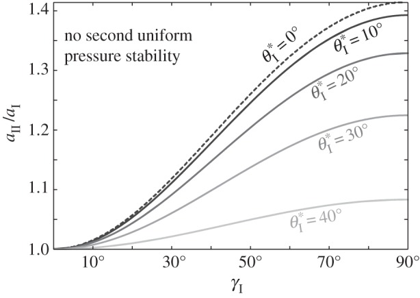
The existence and values of the secondary branch stable folding angle  with respect to Miura-Ori designs, assuming b = aI. The designs to the left of the dashed curve do not lead to secondary branch stability. The corresponding
  values for the designs to the right are shown by the contour lines.
6. Pressure–stability relationship in a dual cell assembly
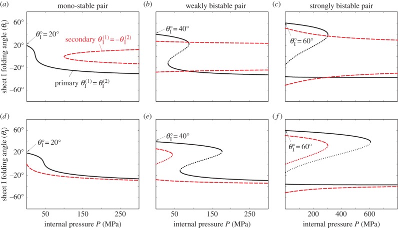
When the crease torsional spring stiffness and internal pressure are both considered, the elastic bistability is coupled with the additional features from the dual-cell interaction; as a result the pressure–stability relationships of the dual cell assembly become more sophisticated compared to an individual cell. When the assembly is under uniform pressure, its stability characteristics can be summarized as follows:
— If the two cells are mono-stable by themselves, the assembly remains mono-stable on its primary folding branch. However, if
 , two additional stable configurations on the secondary folding branch will appear when the applied pressure rises above a critical level, and their corresponding folding angles converge to
  as pressure continues to increase (figure 12a).
— If the two cells are weakly bistable by themselves, the assembly can be tri-stable without pressure, with one stable configuration on the primary folding branch and two on the secondary branch. As pressure increases, the pressure–stability relationship on the primary branch is similar to that of an individual cell. If
 the two stable configurations on the secondary branch continue to exist and their folding angles converge to
  as pressure increases; otherwise they will merge and disappear at a critical pressure level (figure 12b).
— If the two cells are strongly bistable by themselves, the assembly's pressure–stability relationships are similar to those of the weakly bistable assembly, except that it has four stable configurations initially (figure 12c).
Figure 12.
Pressure–stability relationship in a pair of fluidic origami cells. The designs of the individual cells are the same as in figure 7. (a–c) Cases with uniform pressurization where two cells are subjected to the same pressure. (d–f) Cases with differential pressurization where only one cell is pressurized. The solid curves are stable folding configurations on the primary folding branch, the dashed curves are the stable configurations on the secondary branch, and the dotted curves are unstable configurations. In these cases,  (Online version in colour.)
Under differential pressure, the pressure–stability relationships on the primary and secondary folding branches are both similar to those of individual cells (figure 12e,f). Generally speaking, when the internal pressure is low ( ), the multi-stable configurations of the dual cell assembly are primarily elastically induced; when the pressure is sufficiently high (
 ), the stability characteristics converge to those shown in figure 10. It is in the intermediate pressure range that fluid origami will experience changes in the values and existence of the stable folding angles, and such controllable changes in stability can lead to very attractive adaptive functions and biological insights as discussed in the following section.
7. Potential impacts on engineering and plant biology
Designing and developing structural or material systems by using fluidic origami as building blocks could achieve some very intriguing features. The pressure-dependent multi-stability enables the fluidic origami to achieve distributed and rapid shape change based on similar principles as in plants like the Venus flytrap. Rapid movement happens when branches of stable configurations disappear or appear at critical pressure levels. For example, fluidic origami can start from resting at one stable configuration, and then by pressurizing it to a critical pressure value, it can be forced to rapidly ‘snap’ to another branch of stable configuration by releasing the stored energy (electronic supplementary material, movie S1). Once the pressure is released, fluidic origami can either snap back to its original configuration or relax to a different shape, depending on the specific pressure–stability relationship.
Furthermore, since even a simple dual-cell assembly can have such rich stability characteristics, multiple fluidic origami cells, each with uniquely synthesized designs, can be integrated to form an adaptive cellular material or structural system with a large number of tailored stable configurations. Such a sophisticated fluidic origami system could switch among its stable configurations by strategically pressurizing different cells to achieve autonomous and efficient shape change or mechanical property tuning, suitable for various applications like morphing aircraft wings and kinetic architectures.
The development of fluidic origami is an example of how the lessons from nature can lead to innovative engineering systems; on the other hand, the physical insights obtained from this study of pressure-dependent multi-stability could provide guidelines for future plant physiology studies at a cellular level. Currently, studies on the impulsive and recoverable movements in plants primarily focus at the organ level. For example, the ‘snap-through’ motion in the Venus flytrap is described by analysing the curvature changes of its trap lobes and treating them as bistable membranes. Although such studies on the macroscopic level offered many valuable insights, they could not provide a holistic picture because the inherently hierarchical and cellular organizations of the plant organs are not considered. And the underlying mechanisms of these rapid movements are still not completely clear.
This research offers two valuable insights to plant rapid movements at a microscopic level. First of all, the multi-stability in fluidic origami originates from the elasticity of the constituent crease material and the interactions between pressurized cells; this observation suggests that the ‘snap-through’ bistable mechanisms in plants could originate from the elastic properties of the motor cell walls and/or the interaction among cells with different turgor pressures. Secondly, the existence of stable folding configurations changes with respect to internal pressure level; this suggests that plants could exploit similar mechanisms to achieve rapid movements. Therefore, this research on pressure-dependent multi-stability in fluidic origami cells could provide guidance for future plant movement study at the cellular level.
8. Summary
This paper discusses the physics of the pressure-dependent multi-stability characteristics of fluidic origami: an adaptive structure/material concept that combines the rich paper-folding topology with the physiological features associated with the impulsive and recoverable plant movements. Three-dimensional fluid-filled tubular cells are developed via well-designed and integrated Miura-Ori sheets, and their internal fluid pressures are strategically controlled like in plant motor cells for nastic movements.
The nonlinear geometric relationships among folding, crease material deformation and the enclosed internal fluidic volume give the fluidic origami surprisingly rich pressure–stability relationships. An individual fluidic origami cell can be elastically bistable from the interaction between its two constituent Miura-Ori sheets. Upon pressurization, the individual cell can switch between mono-stable and bistable at critical pressure levels. When two pressurized cells are stacked together, additional stable configurations can occur from their interactions. The existence and values of the corresponding stable-folding angles can be controlled by internal pressurization. As a result, fluidic origami can switch between being mono-stable, bistable and multi-stable when the pressure reaches specific critical levels. Such pressure–stability relationships can be tailored by assigning Miura-Ori crease geometries, the torsional stiffness difference between crease lines, and the stress-free stable folding configurations.
This research mainly focuses on the understanding of the fundamental physics of pressure-dependent multi-stability of an individual fluidic origami cell and from dual cell interaction. The findings can be the building blocks towards future development of sophisticated, multicellular fluidic origami structures or materials at different size scales that are capable of distributed and rapid shape morphing and have tuneable mechanical properties. And these findings can also provide valuable insights into the physiology of plant movement at the cellular level.
Supplementary Material
Competing interests
We declare we have no competing interests.
Funding
This research is supported by the University of Michigan Mechanical Engineering Collegiate Professorship.
References
- 1.Burgert I, Fratzl P. 2009. Actuation systems in plants as prototypes for bioinspired devices. Phil. Trans. R. Soc. A 367, 1541–1557. ( 10.1098/rsta.2009.0003) [DOI] [PubMed] [Google Scholar]
- 2.Forterre Y. 2013. Slow, fast and furious: understanding the physics of plant movements. J. Exp. Bot. 64, 4745–4760. ( 10.1093/jxb/ert230) [DOI] [PubMed] [Google Scholar]
- 3.Forterre Y, Skotheim JM, Dumais J, Mahadevan L. 2005. How the Venus flytrap snaps. Nature 433, 421–425. ( 10.1038/nature03185) [DOI] [PubMed] [Google Scholar]
- 4.Markin VS, Volkov AG, Jovanov E. 2008. Active movements in plants. Plant Signal. Behav. 3, 778–783. ( 10.4161/psb.3.10.6041) [DOI] [PMC free article] [PubMed] [Google Scholar]
- 5.Poppinga S, Joyeux M. 2011. Different mechanics of snap-trapping in the two closely related carnivorous plants Dionaea muscipula and Aldrovanda vesiculosa. Phys. Rev. E 84, 041928 ( 10.1103/PhysRevE.84.041928) [DOI] [PubMed] [Google Scholar]
- 6.Volkov AG, Harris SL II, Vilfranc CL, Murphy VA, Wooten JD, Paulicin H, Volkova MI, Markin VS. 2013. Venus flytrap biomechanics: forces in the Dionaea muscipula trap. J. Plant Physiol. 170, 25–32. ( 10.1016/j.jplph.2012.08.009) [DOI] [PubMed] [Google Scholar]
- 7.Darwin C. 1875. Insectivorous plants. London, UK: D. Appleton. [Google Scholar]
- 8.Vincent O, Weißkopf C, Poppinga S, Masselter T, Speck T, Joyeux M, Quilliet C, Marmottant P. 2011. Ultra-fast underwater suction traps. Proc. R. Soc. B 278, 2909–2914. ( 10.1098/rspb.2010.2292) [DOI] [PMC free article] [PubMed] [Google Scholar]
- 9.Findlay GP. 1982. Generation of torque by the column of stylidium. Aust. J. Plant Physiol. 9, 271–286. [Google Scholar]
- 10.Dumais J, Forterre Y. 2012. ‘Vegetable dynamicks’: the role of water in plant movements. Annu. Rev. Fluid Mech. 44, 453–478. ( 10.1146/annurev-fluid-120710-101200) [DOI] [Google Scholar]
- 11.Huber JE, Fleck NA, Ashby AM. 1997. The selection of mechanical actuators based on performance indices. Proc. R. Soc. Lond. A 453, 2185–2205. ( 10.1098/rspa.1997.0117) [DOI] [Google Scholar]
- 12.Skotheim JM, Mahadevan L. 2005. Physical limits and design principles for plant and fungal movements. Science 308, 1308–1310. ( 10.1126/science.1107976) [DOI] [PubMed] [Google Scholar]
- 13.Freeman E, Weiland LM. 2009. High energy density nastic materials: parameters for tailoring active response. J. Intell. Mater. Syst. Struct. 20, 233–243. ( 10.1177/1045389X08092276) [DOI] [Google Scholar]
- 14.Pagitz M, Bold J. 2013. Shape-changing shell-like structures. Bioinspir. Biomim. 8, 016010 ( 10.1088/1748-3182/8/1/016010) [DOI] [PubMed] [Google Scholar]
- 15.Vasista S, Tong L. 2013. Topology-optimized design and testing of a pressure-driven morphing-aerofoil trailing-edge structure. AIAA J. 51, 1898–1907. ( 10.2514/1.J052239) [DOI] [Google Scholar]
- 16.Barrett RM, Barrett CM. 2014. Biomimetic FAA-certifiable, artificial muscle structures for commercial aircraft wings. Smart Mater. Struct. 23, 074011 ( 10.1088/0964-1726/23/7/074011) [DOI] [Google Scholar]
- 17.Lv J, Liu H, Zhang HW. 2014. A multiscale co-rotational method for geometrically nonlinear shape morphing of 2D fluid actuated cellular structures. Mech. Mater. 79, 1–14. ( 10.1016/j.mechmat.2014.08.004) [DOI] [Google Scholar]
- 18.Dicker MPM, Rossiter JM, Bond IP, Weaver PM. 2014. Biomimetic photo-actuation: sensing, control and actuation in sun-tracking plants. Bioinspir. Biomim. 9, 036015 ( 10.1088/1748-3182/9/3/036015) [DOI] [PubMed] [Google Scholar]
- 19.Lee H, Xia C, Fang NX. 2010. First jump of microgel; actuation speed enhancement by elastic instability. Soft Matter 6, 4342–4344. ( 10.1039/c0sm00092b) [DOI] [Google Scholar]
- 20.Kim SW, Koh JS, Lee JG, Ryu J, Cho M, Cho KJ. 2014. Flytrap-inspired robot using structurally integrated actuation based on bistability and a developable surface. Bioinspir. Biomim. 9, 036004 ( 10.1088/1748-3182/9/3/036004) [DOI] [PubMed] [Google Scholar]
- 21.Shahinpoor M. 2011. Biomimetic robotic Venus flytrap (Dionaea muscipula Ellis) made with ionic polymer metal composites. Bioinspir. Biomim. 6, 046004 ( 10.1088/1748-3182/6/4/046004) [DOI] [PubMed] [Google Scholar]
- 22.Tachi T, Miura K. 2012. Rigid-foldable cylinders and cells. J. Int. Assoc. Shell Spat. Struct. 53, 217–226. [Google Scholar]
- 23.Schenk M, Guest SD. 2013. Geometry of miura-folded metamaterials. Proc. Natl Acad. Sci. USA 110, 3276–3281. ( 10.1073/pnas.1217998110) [DOI] [PMC free article] [PubMed] [Google Scholar]
- 24.Li S, Wang KW. 2015. Fluidic origami: a plant inspired adaptive structure with shape morphing and stiffness tuning. Smart Mater. Struct. 24, 105031 ( 10.1088/0964-1726/24/10/105031) [DOI] [Google Scholar]
- 25.Schenk M, Viquerat AD, Seffen KA, Guest SD. 2014. Review of inflatable booms for deployable space structures: packing and rigidization. J. Spacecr. Rockets 51, 762–778. ( 10.2514/1.A32598) [DOI] [Google Scholar]
- 26.Daynes S, Trask RS, Weaver PM. 2014. Bio-inspired structural bistability employing elastomeric origami for morphing applications. Smart Mater. Struct. 23, 125011 ( 10.1088/0964-1726/23/12/125011) [DOI] [Google Scholar]
- 27.Silverberg JL, Evans AA, McLeod L, Hayward RC, Hull TC, Santangelo CD, Cohen I. 2014. Using origami design principles to fold reprogrammable mechanical metamaterials. Science 345, 647–650. ( 10.1126/science.1252876) [DOI] [PubMed] [Google Scholar]
- 28.Silverberg JL, Na JH, Evans AA, Liu B, Hull TC, Santangelo CD, Lang RJ, Hayward RC, Cohen I. 2015. Origami structures with a critical transition to bistability arising from hidden degrees of freedom. Nat. Mater. 14, 389–393. ( 10.1038/nmat4232) [DOI] [PubMed] [Google Scholar]
- 29.Hanna BH, Lund JM, Lang RJ, Magleby SP, Howell LL. 2014. Waterbomb base: a symmetric single-vertex bistable origami mechanism. Smart Mater. Struct. 23, 094009 ( 10.1088/0964-1726/23/9/094009) [DOI] [Google Scholar]
- 30.Waitukaitis S, Menaut R, Chen BG, Van Hecke M. 2015. Origami multistability: from single vertices to metasheets. Phys. Rev. Lett. 114, 055503 ( 10.1103/PhysRevLett.114.055503) [DOI] [PubMed] [Google Scholar]
Associated Data
This section collects any data citations, data availability statements, or supplementary materials included in this article.


