

Introduction
There is increasing interest in sodium MRI for musculoskeletal (MSK) and brain applications, and efficient radio-frequency (RF) coils are essential to unlocking the full potential of this work. There are a number of challenges for RF coil design for sodium MRI. The natural abundance of sodium in the tissues of interest is typically only 0.05% that of protons, and the NMR sensitivity of sodium is only 9.3% that of protons, so maximizing coil sensitivity is essential. Since the gyromagnetic ratio γ of sodium is 11.262 MHz T-1 compared to 42.576 MHz T-1 for protons, its Larmor frequency is much lower than that of protons, for example 34.9 MHz compared to 127.7 MHz for protons at 3 T. Low operating frequencies can lead to problems maintaining good coil loading, limiting sensitivity. Because of the very short T2 of sodium, very short RF pulses are desired to minimize echo time, which motivates a highly efficient transmit coil to limit the maximum voltages needed. It is often also desired for the same coil to provide proton imaging capability, allowing shimming of the B0 field, anatomical reference for the sodium images and even clinical sequences co-registered with the sodium images. Such dual-tuned or dual-frequency designs inevitably involve compromises and added complexities, and the usual strategy is to minimize any sensitivity penalty for the sodium part of the coil. The implementation of multichannel array coil designs for sodium MRI can present even more challenges, particularly with dual frequency designs. In this paper the principles of RF coil optimization for sodium MRI will be explored, and various strategies for addressing these challenges will be reviewed.
RF Coil Basics
The two workhorse RF coil designs for MRI are the surface coil and the birdcage (1) (Fig 1). The surface coil consists of a conductive loop with several breaks in it across which capacitors have been placed. Appropriate choice of the capacitor values relative to the inductance of the loop brings the coil into resonance at the Larmor frequency. To maximize the sensitivity of the RF coil it is necessary to minimize resistive losses in the coil compared to the unavoidable resistive losses in the body. This can be characterized by examining the quality factor Q of the coil. A simple definition of Q is the center frequency of the resonance divided by the width of the resonance at the -3 dB points, hence a narrower resonance corresponds to a higher Q. Q is also given by Q=ωL/R, where ω is the frequency, L the inductance of the circuit and R the resistance. Thus for a particular coil structure with fixed inductance, changes in Q tell us directly about changes in the resistance of the system. The aim of the coil designer is to make the Q of the coil as high as possible when it is unloaded (when the coil is in free space and far from human tissue or conductive samples), and then to have the Q change to a substantially lower value when the coil is loaded by placing it next to the object being imaged. The change in Q is characterized by the Q ratio QUL / QL, the unloaded Q divided by the loaded Q. From this ratio we can approximate what percentage of SNR the coil will achieve, with its inherent coil losses, compared to a theoretical perfect lossless coil, according to the equation SNRREAL/SNRPERFECT = (1-QL/QUL)1/2 (2). We would like the Q ratio to be as high as possible, and generally choose it to be higher than around 3, which would correspond to the coil achieving 81% of the SNR of a perfect lossless coil. The surface coil can provide very high sensitivity in regions immediately adjacent to the coil, but only over a small field of view and with strong signal inhomogeneity.
Figure 1. Schematic diagrams of a surface coil (left) and a birdcage coil (right).
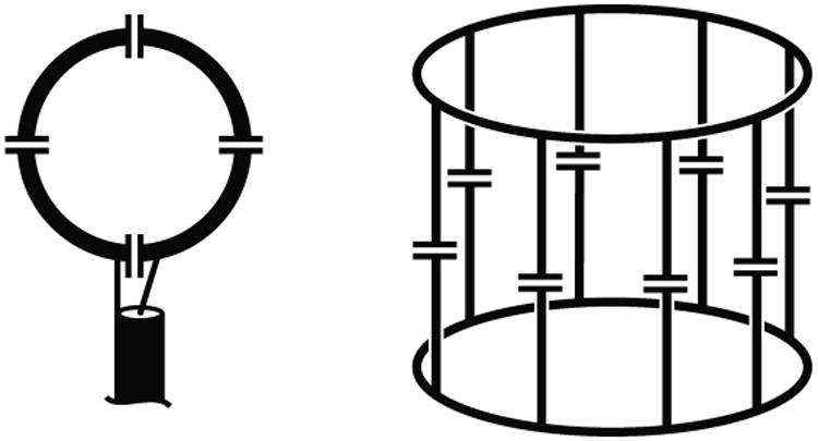
One answer to the limitations of the surface coil is the birdcage coil (1) illustrated on the right of Figure 1. A conductive structure of end rings and rungs is built on a cylindrical former with breaks bridged by capacitors, typically either in the end rings or in the rungs. Appropriate choice of capacitors allows this structure to exhibit a number of resonant modes, one of which creates a highly uniform RF magnetic field within the volume of the coil. In fact this mode is degenerate, with two orthogonal modes at the same frequency. These modes may be driven independently, and with the correct phase relationship it is possible to achieve quadrature excitation and detection, boosting the efficiency of the coil by approximately 41% (3,4). The sensitivity achieved with a birdcage coil is substantially less than that which can be achieved in a small region of interest with a surface coil, but the homogeneity of excitation and reception of the birdcage are highly beneficial, and this design is used widely in sodium coils for brain and extremity imaging.
It is possible to combine the use of surface coils and the birdcage coil to get the best of both worlds by using a multitude of surface coils combined into a surface coil array (5). When properly constructed, it is possible for an array to get the same central SNR as a birdcage of the same dimensions, and substantially higher SNR at the periphery (6). In fact, it is possible to get higher central SNR with an array in many cases because surface coil arrays can be wrapped tightly around irregularly shaped objects in conformations that would not be possible with a birdcage coil. With the use of a surface coil array, generally a birdcage coil is used for excitation to achieve a relatively uniform excitation, with the surface coil array detuned during the transmit phase.
Dual Frequency Coils
For many applications it is desirable to have an RF coil which can operate at both the sodium and proton MR frequencies. For example, to maximize sodium MRI performance it is important to maximize the uniformity of the main B0 static magnetic field. This is most robustly achieved by utilizing proton-based methods to map the B0 field to calculate the correct shim currents. In the absence of a dual-frequency coil some researchers image first with a proton coil to determine the shim currents and then carefully swap to a sodium coil while maintining subject positioning (7,8). A dual-frequency coil improves both the workflow and the quality of the achieved B0 shim, since replacement of the coil inevitably introduces shim variations. Many approaches have been demonstrated for achieving dual frequency operation. One of the simplest and earliest methods used is to have a separate coil structure for each frequency. One issue that arises in such designs however is that the proton coil may excite currents in the lower frequency coil, which has a relatively low impedance at the proton frequency, despite the large difference in resonance frequencies (9). This can be addressed by using coil geometries which are intrinsically decoupled, such as butterfly-loop surface coil combinations (9-11) or coils with high impedance traps tuned to block the response of the lower frequency coil at the proton frequency (12,13). These designs typically have different B1 field patterns for each coil structure, which is not ideal.
An alternative approach is to dual-tune a single coil structure- to make it resonate at two different frequencies of interest. One approach to dual tuning is the use of multiple pole circuits, described in detail by Schnall et al (14). A trap circuit, consisting of a parallel inductor and capacitor, is incorporated into the coil. Rather than blocking current at a specific frequency, as discussed above, in this case the parallel resonant circuit is used to cause a single structure to resonate at two different frequencies. This can be used in simple surface coils, or extended to birdcage designs by incorporating a trap in every rung or between every rung of the birdcage (15-17). The incorporation of a lumped element inductor into the resonant circuit inevitably introduces losses, reducing transmit efficiency and SNR at both frequencies. By choosing the appropriate value for this inductor it is possible to limit losses at the lower frequency to 10 – 20% compared to a single-tuned coil while accepting losses of 50% or more at the proton frequency (14-16).
Dual tuning can also be achieved with the transformer coupled circuit approach (18-20). In this, strong inductive coupling between two resonant structures results in a split resonance in which the lower frequency mode has co-rotating currents and exhibits minimal loss compared to a single resonant coil. The higher frequency mode has counter-rotating currents, and this incurs an SNR penalty on the order of 50% at the higher proton frequency. This has been implemented in both surface coil and birdcage designs.
Another interesting approach to dual tuning involves the construction of a birdcage with four end rings instead of the usual two (21). The inner section operates at the lower frequency, and the outer two sections are tuned near the proton frequency but couple to form a split resonance, one branch of which creates a highly uniform excitation. The efficiency of the lower frequency portion of the coil is close to that of an equivalent single tuned coil. The efficiency of the proton resonator is claimed to be 85% compared to a single tuned structure, but this is in comparison to a single tuned version of the extended double coupled birdcage structure and not to a simple birdcage equivalent of the low frequency central portion of the coil. This design has similarities to an earlier design (22) where additional end rings were used to form an Alderman-Grant coil (23) operating at the proton frequency, but in the earlier design the Alderman-Grant coil provided only linear rather than quadrature excitation for the proton frequency.
The birdcage structure can also be made dual-tuned by perturbing the value of alternating capacitors in the end rings (24). This removes the degeneracy of the two uniform modes and shifts them to different frequencies. It is only practical for small differences in frequency between the resonant modes and hence has not been applied for proton and sodium imaging. It also has the disadvantage that operation at each frequency is linear rather than quadrature. A more general approach has been described in which alternating rung capacitors have substantially different values (25), and this is applicable to arbitrary frequency differences and indeed to more than two resonant frequencies, as well as maintaining quadrature operation at each frequency. The original paper does not offer efficiency comparisons for this approach. Implementations of this design for two frequencies have incorporated trap circuits in the rungs responsible for the lower frequency resonance, in this case not to produce dual resonance but to block currents being induced in them at the higher frequency, which otherwise would degrade performance at the higher frequency (26,27). These trap circuits will necessarily degrade performance at the lower frequency, but very small losses are claimed in the published literature. In a somewhat similar vein, alternating rungs of a TEM volume coil can be tuned to alternating frequencies to yield a dual tuned coil (28-32) with full quadrature operation at both frequencies. No quantitative metrics of coil performance have been offered for this design. A similar design has been realized with microstrip transmission lines (33).
High Performance 23Na Coils for Musculoskeletal Applications
The standard approach for maximizing sensitivity in 1H coils is the use of close-fitting multi-element arrays while using the scanner body coil for RF transmission (5). There are however several challenges in applying this approach to sodium imaging. One of the major concerns is the issue of coil loading. As a simplified example, if a single-row 8 channel receive array was constructed on a 20.3 cm diameter cylinder for knee imaging, a typical element size, allowing for overlap to null mutual inductance, would be 10 × 15 cm. A series of such coils tuned to different frequencies were loaded by placing them 2 cm from a torso sized phantom with εr = 36.2, s = 0.459. Q values and Q ratios for various constructed test coils are shown in Table 1. At each frequency the number of capacitors used in the coil was adjusted to maximize the unloaded Q, with fewer capacitors at lower frequencies. Distributing capacitance unnecessarily by using too many capacitors can increase coil losses and lower the unloaded Q. The unloaded Q values increase with increasing frequency up to 78.6 MHz, above which they drop down again. The unloaded Q drop at high frequency can probably be attributed to radiation loss, which increases approximately as the fourth power of frequency (34). The loaded Q values decrease strongly with increasing frequency, owing to increased conductive losses in the phantom, and thus the Q ratio increases steadily with frequency. A higher Q ratio corresponds to a smaller percentage of coil noise compared to sample noise, and is desirable. Figure 2 shows a graph of coil performance, the percentage of SNR achieved by the coil compared to a theoretical perfect coil with no coil losses, as a function of frequency, based on this data. It can be seen that at frequencies below ∼50 MHz where the Q ratio is very low, coil performance drops below 50%. An array of these dimensions would be quite adequate for proton imaging at 1.5 T and higher, but would provide disappointing results for sodium imaging except at 7 T and higher, since at the 7 T sodium frequency of 78.6 MHz body loading is more favorable. These problems could be addressed in a particular coil design by using fewer, larger elements, or by placing the coils closer to the body.
Table 1.
Unloaded and loaded Q values for a 10 × 15 cm surface coil at a variety of operating frequencies. Higher Q ratios correspond to better coil performance. The number of capacitors in the coil was varied with frequency to achieve optimal unloaded Q in each case.
| Freq. (MHz) | QU | QL | QU / QL | Capacitors |
|---|---|---|---|---|
| 16.3 | 250 | 210 | 1.19 | 2 |
| 32.6 | 360 | 215 | 1.67 | 2 |
| 63.9 | 350 | 160 | 2.19 | 2 |
| 78.6 | 430 | 130 | 3.31 | 2 |
| 123.2 | 390 | 75 | 5.20 | 4 |
| 297.0 | 115 | 20 | 5.75 | 8 |
Figure 2.

Coil performance for an 8 × 10 cm surface coil loaded by a tissue equivalent phantom, given as percentage of actual coil SNR compared to the same coil with no coil losses, based on Q measurements. Dotted line is a least squares fit to the data excluding the 297 MHz data point. Solid circles are 1H frequencies and open circles are 23Na frequencies at 1.5, 3 and 7T.
At ultra-high field (≥7 T) it should be possible to design arrays of small surface coils at the 23Na frequency and still maintain good coil loading. This has been demonstrated in a single resonant 15 channel 23Na knee coil for 7 T (35). Based closely on the design of a commercial 1H knee coil for 3 T (36) (QED Mayfield Village OH), it has fifteen 12 × 9 cm loops and uses a 12 rung birdcage for transmit. No figures are given for the Q ratios achieved with the coil, but it can be presumed that they were adequate since the SNR achieved in the center of the coil was approximately 20% higher than with a slightly larger single resonant birdcage coil, and in the periphery boosts of 1.6-fold were observed. This coil has also been used to good effect for ankle imaging (37).
Incorporating 1H functionality into a 23Na array coil at ultra-high field presents some challenges. An obvious solution would seem to be dual-tuning the 23Na transmit birdcage and also using it as a transmit-receive coil for 1H imaging. The problem that arises is that the 23Na receive array apparatus, which lies between the 1H coil and the body, acts as a partial shield, distorting the B1 field produced by the 1H coil. The 23Na apparatus presents a low impedance at the 1H frequency, and hence currents may be excited on it (9). This could be avoided by introducing blocking traps in the 23Na structure, but this will necessarily introduce losses and degrade the 23Na SNR performance. One approach that has been taken to overcome these issues is to invert the early dual-tuned surface coil designs in which a smaller low frequency loop was placed within a larger 1H loop coil (12,13), and instead place smaller transmit-receive 1H elements co-planar and within the loops of the 23Na structure (38-41). The 23Na loop is almost unaffected by the presence of the 1H loop. The 1H loop does excite some current in the surrounding 23Na loop, which provides a weak shielding effect (42). The shielding does not significantly distort the B1 fields it produces but does slightly reduce the penetration of the element. This is summarized in Figure 3, which shows the unloaded and loaded Q values for various constructed test coils at the 7 T 23Na and 1H frequencies in a number of different configurations. For the offset and concentric coil arrangements the 23Na Q values are only slightly reduced in the presence of the 1H element. However, in the 23Na / 1H offset case the 1H coil has slightly higher unloaded Q in the presence of the 23Na element, presumably due to reduced radiation loss because of the shielding effect of the 23Na coil, but also a much lower Q ratio because the loaded Q is so much higher. The higher loaded Q for the 1H element in this case is not simply due to the increased distance from the sample, as can be seen for the case of the 1H coil offset on its own, where the loaded Q is 15. The higher loaded Q for the 1H coil when the 23Na coil is under it can be attributed to the shielding effect of the 23Na coil, which prevents the 1H coil from coupling effectively with the sample. For the concentric case the 1H coil Q ratio is much improved compared to the offset case, though still not matching that of the single 1H coil on its own. For the dual tuned case, the Q ratio drops for both frequencies, with a much greater penalty for the 1H resonance. We can see that for 23Na the nested co-planar approach can maintain almost the full performance of a single element, while allowing for close coupling between the 1H element and the sample.
Figure 3.
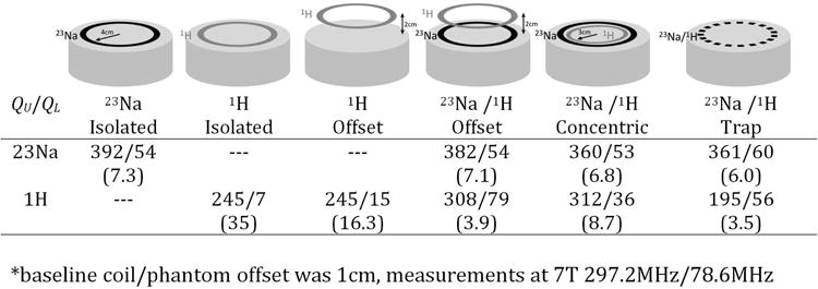
Unloaded / Loaded Q values for 23Na and 1H surface coils in various configurations at 7 Tesla. Q ratios shown in parentheses. Coil inner radius is 4 cm (3 cm for inner concentric coil) and where 1H coil is offset it is an additional 2 cm above the phantom.
The nested co-planar loop approach has been used to create a high-performing 8-channel 23Na array for 7 T knee imaging with 1H capability (38). The coil consists of a close-fitting array of eight 8.8 × 15 cm surface coil loops on a 20.3 cm diameter cylindrical former (Figure 4). Around this is a 25.4 cm diameter detunable 23Na birdcage coil that is used for transmission and which can also be used as a receive coil for a uniform signal reference. A small rectangular 1H element (3 × 7 cm) is placed in the middle of every other 23Na receive loop, creating a 4 channel transmit-receive array. The Q ratio for a 23Na element in the presence of all other 23Na apparatus was 2.7, dropping to 2.6 when the 1H elements were added. Compared to a 20 cm diameter single-resonant 23Na birdcage coil (Rapid Biomedical, Wurzburg, Germany) the central SNR was 10% higher, with gains up to 2.3-fold in the periphery. The transmit efficiency of this design was significantly lower than that of the single-resonant 23Na birdcage coil, due to the larger diameter transmit birdcage used here and the incorporated detuning circuitry. The 1H array provided SNR comparable to a 21 cm diameter single-resonant 1H birdcage coil (Invivo Corp. Gainesville FL), though with a slightly reduced field of view in the superior-inferior direction.
Figure 4.
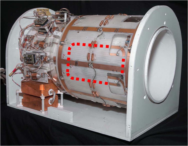
7 Tesla 8ch 23Na / 1H Knee Coil. Inner layer of 23Na and 1H surface coils can be glimpsed through holes in the outer birdcage. Hidden parts of a single 23Na surface coil are depicted with red dotted line.
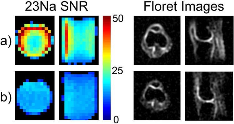
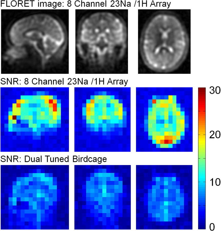
The nested-coplanar approach has also been applied in a 3 T knee coil design (41). Several modifications to the 7 T coil design were required. In particular, it was found that an array of 8 elements on a 20 cm housing would have an insufficient Q ratio due to reduced coil loading at the lower frequency, as discussed above in relation to Figure 2. To address this, a flexible array was designed with a minimum diameter of 15 cm which improved coil loading by maintaining close proximity to the knee in a range of body sizes (Figure 5). The array consisted of six 7.9 × 15 cm 23Na elements and achieved a Q ratio of 1.9. High coupling between coil elements on opposite sides of the posterior gap in the flexible array has the potential to reduce SNR due to preamp noise coupling (43,44). This was mitigated through the implementation of a broadband match strategy (45). 23Na excitation is provided by a 25 cm diameter mono-resonant detunable birdcage coil. A 3.2 cm × 10 cm 1H loop was placed concentric and coplanar with each 23Na element, creating a 6 channel 1H transmit-receive array on the flexible inner former. When compared to a 20 cm diameter mono-resonant 23Na birdcage (Stark Contrast, Erlangen Germany), the 23Na array showed 30% higher SNR in the center and 2-fold improvements in the periphery (Figure 6). SNR was calculated according to the Kellman method (46) from GRE acquisitions with and without RF excitation. 23Na images were obtained with a FLORET sequence (47) at 4 mm isotropic resolution in 8.5 minutes and clearly show the higher SNR of the 23Na array (Figure 6, right). Transmit efficiency was the same for the 23Na array and the mono-resonant 23Na extremity birdcage with a 1 ms hard pulse of 200v producing a 180 flip angle in the center of the knee. The 1H array achieved central SNR 15% better than a single-resonant 20 cm diameter extremity birdcage, but 35% less than an 18 cm diameter 15 channel 1H knee coil (QED Mayfield Village OH). The close proximity of the 1H elements resulted in some transmit non-uniformity, but this did not prevent the generation of clinical quality TSE images.
Figure 5.
3 Tesla 6ch 23Na / 1H Knee Coil. Inner array is flexible to conform to various body types. Small rectangular 1H elements can be seen inside two of the 23Na elements in the posterior portion of the array.
Figure 6. 23Na SNR and example anatomical images for the 3 Tesla 6 channel flexible knee array and a 20 cm diameter single frequency extremity coil.
Another approach which has been demonstrated for knee imaging is using a close-fitting transmit-receive array for 23Na with a transmit-receive 1H coil surrounding it on a larger diameter shell. A 3 T version of this design with eight 23Na coils and a 4-channel 1H transmit-receive array (48) demonstrates some of the challenges discussed above. The central SNR of the 15 cm diameter 23Na array is substantially lower than a single-resonant birdcage (diameter not given), and SNR gain is only achieved in the extreme periphery. This can probably be attributed to poor coil loading, though Q values are not given in the published work. In addition, the 1H elements exhibit distorted B1 profiles, which can likely be attributed to the shielding effects of the 23Na apparatus. Nevertheless, the combination of the four 1H elements was sufficient for anatomical localization. At 7 T the design was modified to incorporate only four 23Na transmit-receive elements on a rather small 13 cm diameter former, surrounded by a 1H birdcage volume coil (49). Between the use of larger elements, a tighter fitting former and the higher field strength the coil loading can be expected to be much better for this design (Q values are not given in the publication), and this is supported by the good SNR performance. The 23Na array achieves central SNR close to that of the compared single-resonant birdcage (diameter not given), and quickly outperforms the birdcage for regions away from the center of the coil. It would be expected that screening by the 23Na apparatus would have a detrimental effect on the 1H birdcage performance, but all that can be gleaned from the small amout of 1H data that is presented is that it is sufficient for anatomical localization.
High Performance 23Na Head Coil Designs
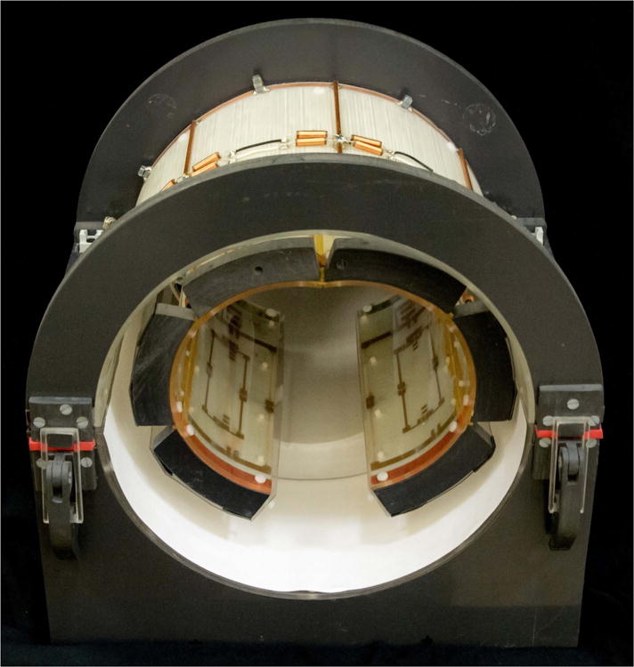
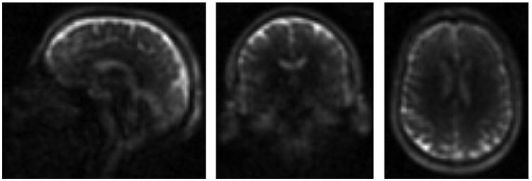
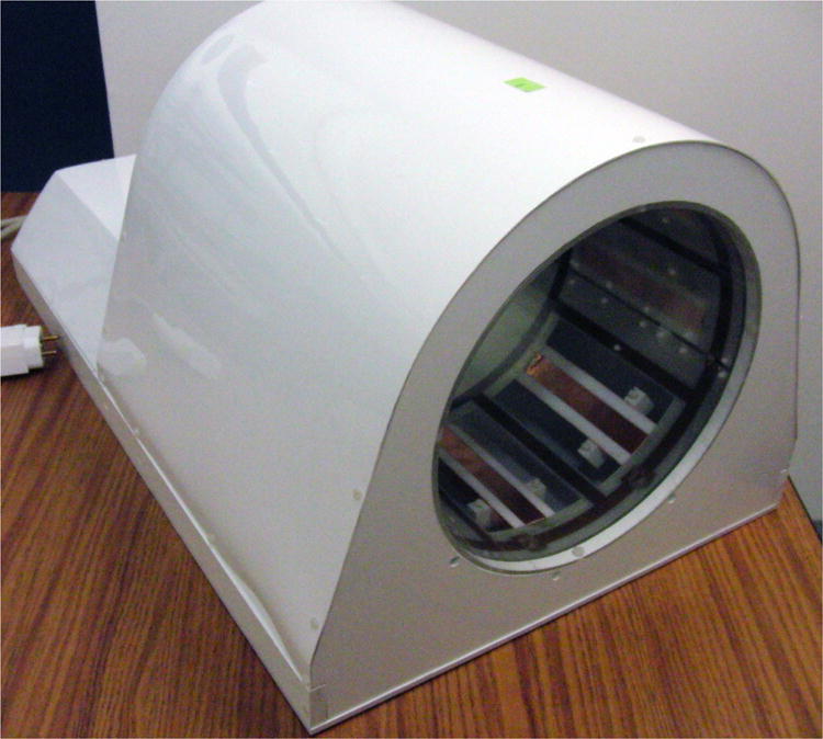
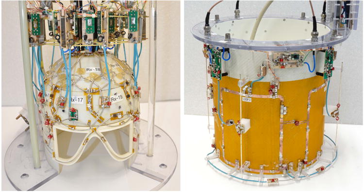
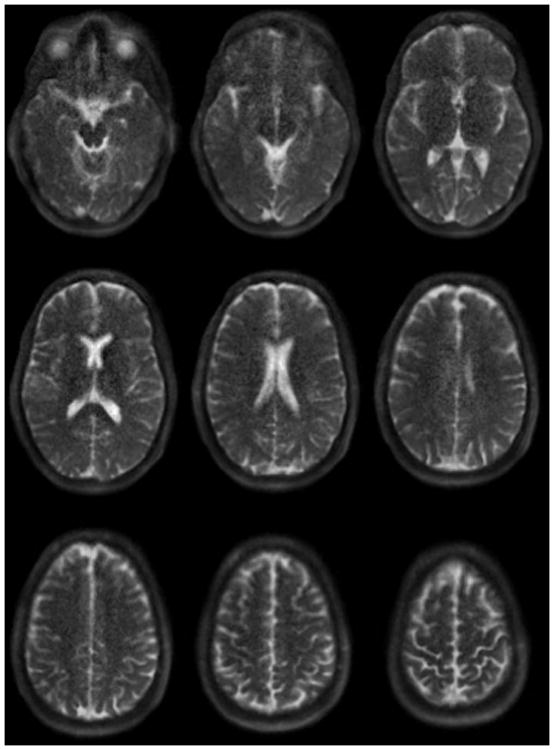
There is a great deal of interest in 23Na brain imaging at ultra-high field (≥7T). The higher intrinsic SNR at higher fields helps to overcome the inherent low sensitivity of the 23Na measurement. For single-resonant coils the operating frequency remains relatively low (78.6 MHz on the Siemens 7 T, for example), so RF design is not complicated by the issues of high frequency and short wavelengths as it is for 1H coils at 7 T. As noted above, multi-element 23Na receive arrays are particularly feasible at 7 T. A 15 channel 7 T head coil has been demonstrated (8). This consists of a close fitting helmet with 15 detunable surface coil loops inside a detunable birdcage (Figure 7) The birdcage is used for transmit and can also be used to receive instead of the array for a uniform signal reference. The published data show high noise correlation, which motivates the use of offline reconstruction with optimal combination through the use of decorrelation (50). The array achieves the same central SNR as the larger transmit-receive volume coil, with substantial SNR gains in the periphery. It might be expected that the smaller overall dimensions of the receive array compared to the volume coil would allow it to display higher central SNR than the volume coil, but this was not achieved with this design. Nevertheless the combination of high field and a close fitting array allows for fast high resolution acquisitions with a custom FLORET sequence (47) such as those shown in Figure 8 (TR/TE/flip = 100 ms / 0.2 ms / 80°, FoV = 288 mm, Nyquist resolution 3 mm isotropic, acquisition time = 12:48). The use of a SENSE parallel imaging reconstruction scheme with uniform image intensity can account for the array's spatially variable sensitivity and allow quantification of 23Na concentration (50).
Figure 7. 7 Tesla 15 channel Head Coil.
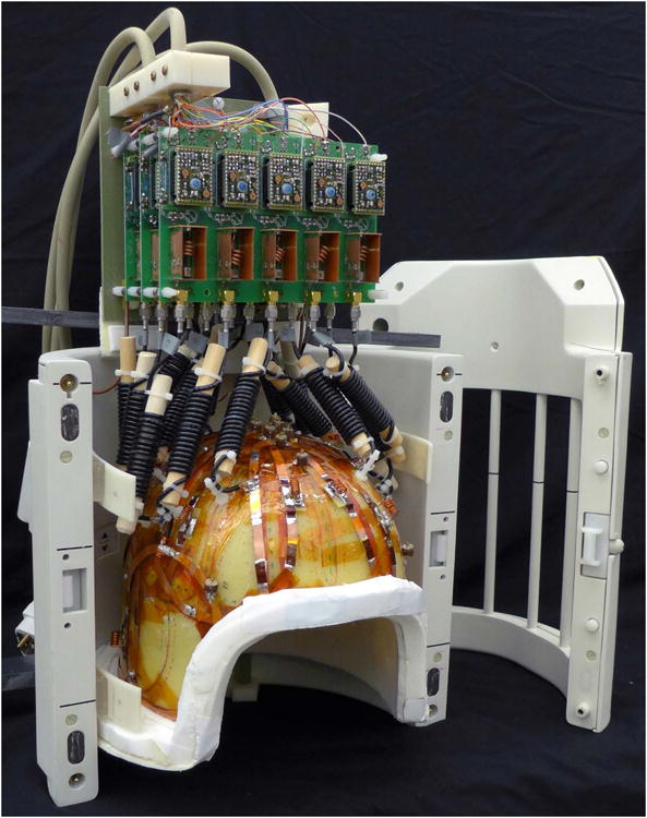
Figure 8. 3mm isotropic FLORET images acquired in 12:39 with the 15 channel 7 Tesla head coil.
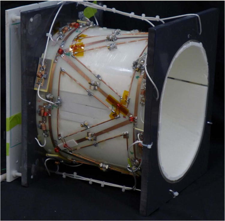
The nested coplanar coil approach described in relation to knee coils above can also be used to create a dual frequency head coil at 7 T. For example, a dual frequency 7 T volume coil has been demonstrated which consists of an 8-rung 23Na birdcage with a 1H stripline element placed between each rung (39) (Figure 9). The presence of the stripline elements with their heavy copper shielding resulted in an SNR drop of 8% compared to the unmodified 23Na birdcage. In 23Na transmit the coil required a 265 volt 1 ms hard pulse to create a 180 degree flip angle in the center of the head. 1H imaging was achieved by driving the 8 channel transmit-receive stripline array with a relatively complicated power-splitter, phasing and T/R switch interface. 1H coil coverage was adequate for shimming and anatomical localization of the supratentorial brain, but 1H SNR was only 68% compared to a commercial 1H birdcage coil (Invivo Corp. Gainesville FL). A variation on this approach has been described at 3 T in which 1H loops are used instead of stripline elements, and the loops are placed such that the 23N birdcage rungs bisect the 1H loops (51). No quantitative performance evaluation was offered for this design.
Figure 9.
7 Tesla 23Na birdcage with coplanar 1H striplines visible through the clear interior shell.
At 9.4T a simpler option for adding 1H functionality to a 23Na birdcage has been demonstrated, using a quadrature driven patch antenna (52,53). Rigorous SNR comparisons to standard designs are not offered, though it is suggested that the close proximity of the patch antenna to the 23Na birdcage allows it to act as an end cap, slightly boosting 23Na SNR at that end of the coil. A more ambitious 9.4T coil has been described with a 27-element close-fitting 23Na receive head array, 4-loop 23Na transmit array and four 1H dipole antennas (54) (Figure 10). At this high frequency even the relatively small 90mm diameter loop coils have a healthy unloaded to loaded Q ratio of 4.7. The 4-loop 23Na transmit array was chosen instead of a birdcage to minimize interaction with the 1H dipole elements. Electric dipole antenna are finding increasing application in ultra-high field proton imaging (55-59), where their performance becomes comparable to or better than conventional loop coils (60). The dipoles in this 9.4T coil are placed so that one dipole bisects each 23Na transmit loop, an arrangement similar to the placement of stripline elements in the 7 T coil described above. However, between the 1H dipole and the head also lies the 27-channel 23Na receive array, the presence of which distorts the B1+ field of the 1H dipole array, as noted in the paper. Nevertheless, whole brain coverage is achieved with the 1H antennas adequate for shimming and anatomical localization. The 23Na receive array was compared to a single tuned 23Na birdcage coil, and while the SNR at the center of the head was 18% lower with the receive array, it quickly outperforms the birdcage as you move away from the center of the head, with gains up to 4-fold in the cortex. 23Na brain images with 1×1×4 mm resolution acquired in 14 minutes are shown in Figure 11.
Figure 10.
9.4 Tesla 23Na / 1H head coil constructed by G. Shajan. Inner coil (left) is a 27 element receive-only 23Na array. Outer coil (right) consists of 4 large 23Na transmit loops and four 1H transmit-receive dipole antennas.
Figure 11.
23Na brain images obtained at 9.4T with the coil in Figure 10 with a stack-of-spirals sequence with TE / TR = 0.3 ms / 150 ms, nominal resolution = 1×1×4 mm, acquired in 14 minutes.
23Na receive head arrays have also been described at lower fields such as a commercially available 30 channel 23Na 3 T head coil (Rapid Biomedical, Wurzburg Germany). The receive array is placed on a close-fitting helmet, which is surrounded by a dual tuned birdcage for 23Na transmit and 1H imaging. Few technical details of the coil have been published, but a recently published paper offers methods for processing the data obtained from this coil (61) and gives some insight into its performance. Compared to a larger diameter dual tuned 23Na / 1H birdcage coil, the 30 channel 23Na array has ∼30% lower central SNR, but this improves steeply moving away from the center, with SNR gains ∼2.7-fold in the cortex. No data are shown for the performance of the 1H channel of the dual tuned birdcage.
A less conventional 3 T head coil design utilizing the nested co-planar loops concept (38) has been described (40). This consists of close-fitting 8 channel transmit-receive arrays for both 23Na and 1H. The 23Na array is based on a triangular coil array design (62) which allows for decoupling of neighboring and next nearest neighbor coils (Figure 12). Within each triangular 23Na element a smaller triangular 1H element is placed, on the same surface of the coil former. The 1H elements are thus able to couple with the head without any intervening 23Na coil apparatus. The surrounding 23Na coil structure provides a partial encircling shield which might be expected to reduce coupling between the 1H elements (42), but inductive decoupling of neighboring 1H elements was still required. Each transmit array was driven via a fairly complex interface that split transmit power equally amongst the elements and provided appropriate phase for quadrature excitation, with T/R switches on each channel for reception. With dimensions of 20 × 25 cm the coil is somewhat snug on larger patients, but this close-fitting design achieved an unloaded to loaded Q ratio of 2.5 for the 23Na elements. When compared to a considerably larger 26 cm diameter dual tuned birdcage (Stark Contrast Erlangen) the 8 channel 23Na array provided 1.6-fold higher SNR (calculated from signal and noise scans according to the Kellman method) in the center of the head and 2.3-fold higher SNR in the periphery (Figure 13). Images obtained with a custom FLORET sequence (47) are shown at the top of Figure 12 (TR/TE/flip = 100 ms / 0.2 ms / 80°, FoV = 320 mm, Nyquist resolution 5mm isotropic, acquisition time = 12:48). In transmit, the 8 channel 23Na array required a 225 volt 1 ms hard pulse to achieve a 180° flip angle in the center of the head, compared to 220 volts for the dual tuned birdcage. Given the smaller size of the 23Na array it might be expected to require a lower voltage than the dual tuned birdcage, but relatively high coupling between opposing coil elements limited the transmit efficiency of the coil. The 1H array provides coverage from the cerebellum to the apex (Figure 14). 1H SNR values through an approximately 5 cm thick transverse slab are at least 65% of the dual tuned birdcage, and drop off to 50% in the inferior temporal and frontal lobes and 45% in the apex. Bench measurements of the coil have so far shown no obvious cause for the very high SNR for the element on patient right, though B1+ maps (discussed below) show that it is not attributable to transmit non-uniformity. The 8 channel 1H array requires a 229 volt 1 ms hard pulse to achieve 180° flip angle in the center of the head, compared to 203 volts for the 1H channel of the dual tuned birdcage. Example B1+ maps for each coil are shown as insets in each SNR map in figure 14. Within the brain, B1+ homogeneity for the 8 channel 1H array is equal or better than the dual tuned birdcage in the transverse plane, but drops off more rapidly in superior and inferior brain regions. An example 1 mm isotropic MPRAGE acquired in 7:51 with the 1H array is shown in Figure 13 (TR/TI/TE/flip = 2100 / 900 / 3.9 / 8°, BW = 260 Hz/pixel, matrix = 256, 192 slices).
Figure 12.
3 Tesla 8ch 23Na / 1H head coil.
Figure 13.
23Na 5 mm isotropic anatomical images obtained with the 3 Tesla 8 channel 23Na / 1H head coil, plus SNR comparison for this coil compared to a dual tuned birdcage coil.
Figure 14.
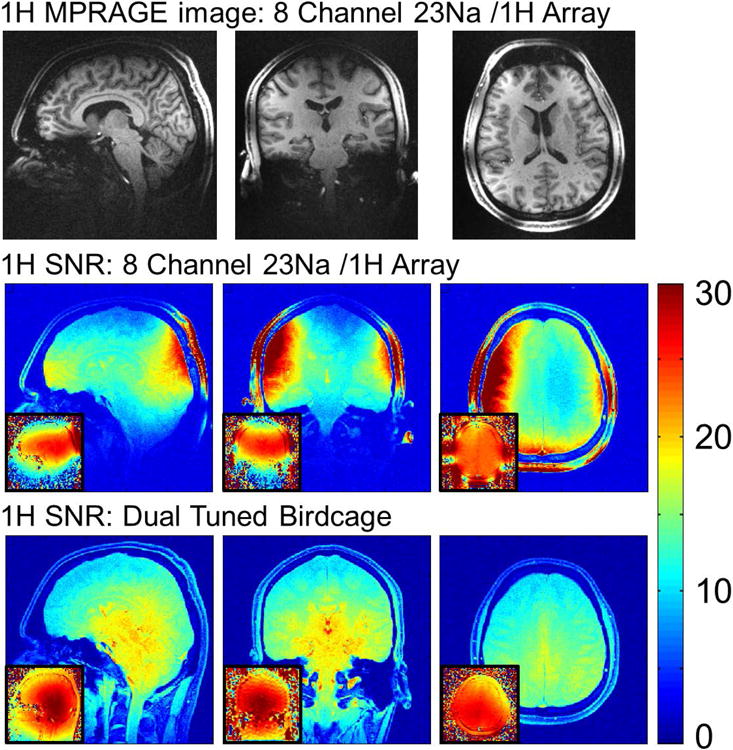
1mm isotropic MPRAGE images obtained with the 1H part of the 3 Tesla 8 channel 23Na / 1H head coil (top) and SNR comparison for the 1H portion of that coil and a dual tuned birdcage for comparison. Small inset figures show B1+ fields for each coil, obtained with a turboflash B1 mapping sequence.
Conclusions
The low sensitivity of the 23Na MR experiment demands the use of optimized RF coils. At standard clinical field strengths the low 23Na operating frequency can result in poor coil loading, requiring caution in implementing many-element designs similar to those used so effectively for 1H imaging. The greatest utility will only be achieved with coil designs that also provide 1H imaging capabilities, but dual tuning degrades the performance at one or both frequencies, and designs with separate 1H antenna structures have to contend with screening effects due to currents induced on the 23Na apparatus. Many clever approaches have been presented here which push the limits of 23Na sensitivity while providing less than optimal 1H performance. The holy grail of a coil which maximizes 23Na sensitivity while providing 1H sensitivity equivalent to an optimized close-fitting 1H array still eludes us, but there remain many opportunities for optimization and innovation in coil design to allow us to approach this goal in the future.
Acknowledgments
The Center for Advanced Imaging Innovation and Research (CAI2R, www.cai2r.net) at New York University School of Medicine is supported by NIH/NIBIB grant number P41 EB017183
The authors would like to thank Guillaume Madelin for the FLORET images in this paper, and Gunamony Shajan for the 9.4 T head coil photographs and 23Na brain images.
References
- 1.Hayes C, Edelstein WA, Schenck JF, Mueller OM, Eash M. An Efficient, Highly Homogeneous Radiofrequency Coil for Whole-Body NMR Imaging at 1.5 T. J Magn Reson. 1985;63:622–628. [Google Scholar]
- 2.Hayes CE, Axel L. Noise performance of surface coils for magnetic resonance imaging at 1.5 T. Med Phys. 1985;12(5):604–607. doi: 10.1118/1.595682. [DOI] [PubMed] [Google Scholar]
- 3.Glover GH, Hayes CE, Pelc NJ, Edelstein WA, Mueller OM, Hart HR, Hardy CJ, O'Donnell M, Barber WD. Comparison of Linear and Circular Polarization for Magnetic Resonance Imaging. J Magn Reson. 1985;64:255–270. [Google Scholar]
- 4.Hoult DI, Chen CN, Sank VJ. Quadrature detection in the laboratory frame. Magn Reson Med. 1984;1(3):339–353. doi: 10.1002/mrm.1910010305. [DOI] [PubMed] [Google Scholar]
- 5.Roemer PB, Edelstein WA, Hayes CE, Souza SP, Mueller OM. The NMR phased array. Magn Reson Med. 1990;16(2):192–225. doi: 10.1002/mrm.1910160203. [DOI] [PubMed] [Google Scholar]
- 6.Wright SM, Wald LL. Theory and application of array coils in MR spectroscopy. NMR Biomed. 1997;10(8):394–410. doi: 10.1002/(sici)1099-1492(199712)10:8<394::aid-nbm494>3.0.co;2-0. [DOI] [PubMed] [Google Scholar]
- 7.Lu A, Atkinson IC, Claiborne TC, Damen FC, Thulborn KR. Quantitative sodium imaging with a flexible twisted projection pulse sequence. Magn Reson Med. 2010;63(6):1583–1593. doi: 10.1002/mrm.22381. [DOI] [PMC free article] [PubMed] [Google Scholar]
- 8.Qian Y, Zhao T, Wiggins GC, Wald LL, Zheng H, Weimer J, Boada FE. Sodium imaging of human brain at 7 T with 15-channel array coil. Magn Reson Med. 2012;68(6):1807–1814. doi: 10.1002/mrm.24192. [DOI] [PubMed] [Google Scholar]
- 9.Bottomley PA, Hardy CJ, Roemer PB, Mueller OM. Proton-decoupled, Overhauser-enhanced, spatially localized carbon-13 spectroscopy in humans. Magn Reson Med. 1989;12(3):348–363. doi: 10.1002/mrm.1910120307. [DOI] [PubMed] [Google Scholar]
- 10.Adriany G, Gruetter R. A half-volume coil for efficient proton decoupling in humans at 4 tesla. J Magn Reson. 1997;125(1):178–184. doi: 10.1006/jmre.1997.1113. [DOI] [PubMed] [Google Scholar]
- 11.Merkle H, Wei H, Garwood M, Ugurbil K. B1-Insensitive Heteronuclear Adiabatic Polarization Transfer for Signal Enhancement. Journal of Magnetic Resonance. 1992;99:480–494. [Google Scholar]
- 12.Alecci M, Romanzetti S, Kaffanke J, Celik A, Wegener HP, Shah NJ. Practical design of a 4 Tesla double-tuned RF surface coil for interleaved 1H and 23Na MRI of rat brain. Journal of Magnetic Resonance. 2006;181:203–211. doi: 10.1016/j.jmr.2006.04.011. [DOI] [PubMed] [Google Scholar]
- 13.Dabirzadeh A, McDougall MP. Trap Design for Insertable Second-Nuclei Radiofrequency Coils for Magnetic Resonance Imaging and Spectroscopy. Concepts in Magn Reson Part B. 2009;35B(3):121–132. [Google Scholar]
- 14.Schnall MD, Subramanian VH, Leigh JS, Chance B. A new double-tuned probe for concurrent 1H and 31P NMR. J Magn Reson. 1985;65:122–129. [Google Scholar]
- 15.Isaac G, Schnall MD, Lenkinski RE, Vogele K. A design for a double-tuned birdcage coil for use in an integrated MRI/MRS examination. J Magn Reson. 1990;89:41–50. [Google Scholar]
- 16.Rath AR. Design and Performance of a Double-Tuned Bird-Cage Coil. Journal of Magnetic Resonance. 1990;86:488–495. [Google Scholar]
- 17.Shen GX, Boada FE, Thulborn KR. Dual-frequency, dual-quadrature, birdcage RF coil design with identical B1 pattern for sodium and proton imaging of the human brain at 1.5 T. Magn Reson Med. 1997;38(5):717–725. doi: 10.1002/mrm.1910380507. [DOI] [PubMed] [Google Scholar]
- 18.Fitzsimmons JR, Beck BL, Brooker HR. Double resonant quadrature birdcage. Magn Reson Med. 1993;30(1):107–114. doi: 10.1002/mrm.1910300116. [DOI] [PubMed] [Google Scholar]
- 19.Fitzsimmons JR, Brooker HR, Beck B. A transformer-coupled double-resonant probe for NMR imaging and spectroscopy. Magn Reson Med. 1987;5(5):471–477. doi: 10.1002/mrm.1910050510. [DOI] [PubMed] [Google Scholar]
- 20.Fitzsimmons JR, Brooker HR, Beck B. A comparison of double-tuned surface coils. Magn Reson Med. 1989;10(3):302–309. doi: 10.1002/mrm.1910100303. [DOI] [PubMed] [Google Scholar]
- 21.Murphy-Boesch J, Srinivasan R, Carvajal L, Brown TR. Two configurations of the four-ring birdcage coil for 1H imaging and 1H-decoupled 31P spectroscopy of the human head. Journal of magnetic resonance Series B. 1994;103(2):103–114. doi: 10.1006/jmrb.1994.1017. [DOI] [PubMed] [Google Scholar]
- 22.Derby K, Tropp J, Hawryszko C. Design and Evaluation of a Novel Dual-Tuned Resonator for Spectroscopic Imaging. Journal of Magnetic Resonance. 1990;86(3):645–651. [Google Scholar]
- 23.Alderman DW, Grant DM. Efficient Decoupler Coil Design Which Reduces Heating in Conductive Samples in Superconducting Spectrometers. Journal of Magnetic Resonance. 1979;36(3):447–451. [Google Scholar]
- 24.Joseph PM, Lu D. A technique for double resonant operation of birdcage imaging coils. IEEE Trans Med Imaging. 1989;8(3):286–294. doi: 10.1109/42.34719. [DOI] [PubMed] [Google Scholar]
- 25.Amari S, Ulug AM, Bornemann J, van Zijl PC, Barker PB. Multiple tuning of birdcage resonators. Magn Reson Med. 1997;37(2):243–251. doi: 10.1002/mrm.1910370217. [DOI] [PubMed] [Google Scholar]
- 26.Matson GB, Vermathen P, Hill TC. A practical double-tuned 1H/31P quadrature birdcage headcoil optimized for 31P operation. Magn Reson Med. 1999;42(1):173–182. doi: 10.1002/(sici)1522-2594(199907)42:1<173::aid-mrm23>3.0.co;2-o. [DOI] [PubMed] [Google Scholar]
- 27.Tomanek B, Volotovskyy V, Gruwel MLH, McKenzie E, King S. Double-Frequency Birdcage Volume Coils for 4.7T and 7T. Magnetic Resonance Part B. 2005;26B(1):16–22. [Google Scholar]
- 28.Vaughan JT, Hetherington HP, Pan JW, Noa PJ, Pohost GM. A high frequency double-tuned resonator for clinical NMR. Proceedings of the 12th Annual Meeting SMRM. 1993:306. [Google Scholar]
- 29.Vaughan JT, Hetherington HP, Otu JO, Pan JW, Pohost GM. High frequency volume coils for clinical NMR imaging and spectroscopy. Magn Reson Med. 1994;32(2):206–218. doi: 10.1002/mrm.1910320209. [DOI] [PubMed] [Google Scholar]
- 30.Chu WJ, Hetherington HP, Kuzniecky RJ, Vaughan JT, Twieg DB, Faught RE, Gilliam FG, Hugg JW, Elgavish GA. Is the intracellular pH different from normal in the epileptic focus of patients with temporal lobe epilepsy? A 31P NMR study. Neurology. 1996;47(3):756–760. doi: 10.1212/wnl.47.3.756. [DOI] [PubMed] [Google Scholar]
- 31.Chu WJ, Hetherington HP, Kuzniecky RI, Simor T, Mason GF, Elgavish GA. Lateralization of human temporal lobe epilepsy by 31P NMR spectroscopic imaging at 4.1 T. Neurology. 1998;51(2):472–479. doi: 10.1212/wnl.51.2.472. [DOI] [PubMed] [Google Scholar]
- 32.Mason GF, Chu WJ, Vaughan JT, Ponder SL, Twieg DB, Adams D, Hetherington HP. Evaluation of 31P metabolite differences in human cerebral gray and white matter. Magn Reson Med. 1998;39(3):346–353. doi: 10.1002/mrm.1910390303. [DOI] [PubMed] [Google Scholar]
- 33.Xie Z, Xu D, Kelley DA, Vigneron DB, Zhang X. ISMRM Workshop on Advances in High Field MR. Pacific Grove, California, USA: 2007. Dual-frequency Volume Microstrip Coil with Quadrature Capability for 13C/1H MRI/MRS at 7T. p Poster 41. [Google Scholar]
- 34.Ong KC, Wen H, Chesnick AS, Duewell S, Jaffer FA, Balaban RS. Radiofrequency shielding of surface coils at 4.0 T. J Magn Reson Imaging. 1995;5(6):773–777. doi: 10.1002/jmri.1880050626. [DOI] [PubMed] [Google Scholar]
- 35.Finnerty M, Yang X, Zheng T, Heilman J, Castrilla N, Herczak J, Fujita H, Wiggins GC, Brown R, Madelin G, Chang G, Raegatte RR, Recht M, Trattnig S, Juras V, Renz W, Schmitt F, Stoeckel B, Potthast A, Wicklow K. A 7-Tesla Transmit with 15-Channel Receive-Only Array Knee Coil for Sodium Imaging. ISMRM; Montreal, Canada: 2011. p. 1900. [Google Scholar]
- 36.Finnerty M, Herczak J, Zheng T, Weaver J, Yang X, Fujita H. A 3D Parallel Imaging Capable Transmit and 15-Channel Receive Array Knee Coil at 3T. Proceedings of the 16th Annual Meeting ISMRM; Toronto Canada. 2008. p. 1077. [PMC free article] [PubMed] [Google Scholar]
- 37.Zbyn S, Brix MO, Juras V, Domayer SE, Walzer SM, Mlynarik V, Apprich S, Buckenmaier K, Windhager R, Trattnig S. Sodium magnetic resonance imaging of ankle joint in cadaver specimens, volunteers, and patients after different cartilage repair techniques at 7 T: initial results. Invest Radiol. 2015;50(4):246–254. doi: 10.1097/RLI.0000000000000117. [DOI] [PMC free article] [PubMed] [Google Scholar]
- 38.Brown R, Madelin G, Lattanzi R, Chang G, Regatte RR, Sodickson DK, Wiggins GC. Design of a nested eight-channel sodium and four-channel proton coil for 7T knee imaging. Magn Reson Med. 2013;70(1):259–268. doi: 10.1002/mrm.24432. [DOI] [PMC free article] [PubMed] [Google Scholar]
- 39.Wiggins GC, Brown R, Fleysher L, Zhang B, Stoeckel B, Inglese M, Sodickson DK. A Nested Dual Frequency Birdcage/Stripline Coil for Sodium/Proton Brain Imaging at 7T. ISMRM; Stockholm, Sweden: 2010. p. 1500. [Google Scholar]
- 40.Lakshmanan K, Brown R, Madelin G, Boada FE, Wiggins G. An 8 Channel Transmit Receive Sodium & Nested 8 Channel Transmit Receive Proton Coil for 3.0 T Brain Imaging. ISMRM; Milan, Italy: 2014. p. 4879. [Google Scholar]
- 41.Brown R, Lakshmanan K, Madelin G, Chang G, Sodickson D, Regatte R, Wiggins G. Design and Application of a Nested Multi-Channel Sodium/Proton Knee Array at 3T. Proceedings of the 22nd Annual Meeting ISMRM; Milan Italy. 2014. p. 4880. [Google Scholar]
- 42.Lanz T, Griswold M. Concentrically Shielded Surface Coils - A New Method for Decoupling Phased Array Elements. Proceedings of the 14th Annual Meeting ISMRM; Seattle WA. 2006. p. 217. [Google Scholar]
- 43.Wiggins GC, Brown R, Zhang B, Vester M, Popescu S, Rehner R, Sodickson D. SNR Degradation in Receive Arrays Due to Preamplifier Noise Coupling and a Method for Mitigation. ISMRM; Melbourne, Australia: 2012. p. 2689. [Google Scholar]
- 44.Reykowski A, Wang J. Rigid Signal-to-Noise Analysis of Coupled MRI Coils Connected to Noisy Preamplifiers and the Effect of Coil Decoupling on Combined SNR. Proceedings of the 8th Annual Meeting ISMRM; Denver CO USA. 2000. p. 1402. [Google Scholar]
- 45.Vester M, Biber S, Rehner R, Wiggins G, Brown R, Sodickson D. Mitigation of Inductive Coupling in Array Coils by Wideband Port Matching. ISMRM; Melbourne, Australia: 2012. p. 2690. [Google Scholar]
- 46.Kellman P, McVeigh ER. Image reconstruction in SNR units: a general method for SNR measurement. Magn Reson Med. 2005;54(6):1439–1447. doi: 10.1002/mrm.20713. [DOI] [PMC free article] [PubMed] [Google Scholar]
- 47.Pipe JG, Zwart NR, Aboussouan EA, Robison RK, Devaraj A, Johnson KO. A new design and rationale for 3D orthogonally oversampled k-space trajectories. Magn Reson Med. 2011;66(5):1303–1311. doi: 10.1002/mrm.22918. [DOI] [PubMed] [Google Scholar]
- 48.Kim JH, Moon CH, Park BW, Furlan A, Zhao T, Bae KT. Multichannel transceiver dual-tuned RF coil for proton/sodium MR imaging of knee cartilage at 3 T. Magn Reson Imaging. 2012;30(4):562–571. doi: 10.1016/j.mri.2011.12.011. [DOI] [PubMed] [Google Scholar]
- 49.Moon CH, Kim JH, Zhao T, Bae KT. Quantitative (23) Na MRI of human knee cartilage using dual-tuned (1) H/(23) Na transceiver array radiofrequency coil at 7 tesla. J Magn Reson Imaging. 2013;38(5):1063–1072. doi: 10.1002/jmri.24030. [DOI] [PubMed] [Google Scholar]
- 50.Pruessmann KP, Weiger M, Bornert P, Boesiger P. Advances in sensitivity encoding with arbitrary k-space trajectories. Magn Reson Med. 2001;46(4):638–651. doi: 10.1002/mrm.1241. [DOI] [PubMed] [Google Scholar]
- 51.Ha S, Friel H, Kruiskamp M, Nalcioglu O. Dual-tuned strip-line loop array H1 / birdcage Na23 RF coil for 3T MRI. ISMRM; Melbourne Australia: 2013. p. 2783. [Google Scholar]
- 52.Mirkes C, Hoffmann J, Shajan G, Pohmann R, Scheffler K. Combination of a sodium birdcage coil with a tunable patch antenna for B0 shimming and anatomical localization at 9.4 T. Proceedings of the 21st Annual Meeting ISMRM; Salt Lake City Utah USA. 2013. p. 1982. [Google Scholar]
- 53.Mirkes CC, Hoffmann J, Shajan G, Pohmann R, Scheffler K. High-resolution quantitative sodium imaging at 9.4 tesla. Magn Reson Med. 2014 doi: 10.1002/mrm.25096. [DOI] [PubMed] [Google Scholar]
- 54.Shajan G, Mirkes C, Buckenmaier K, Hoffmann J, Pohmann R, Scheffler K. Three-layered radio frequency coil arrangement for sodium MRI of the human brain at 9.4 Tesla. Magn Reson Med. 2015 doi: 10.1002/mrm.25666. Early view. [DOI] [PubMed] [Google Scholar]
- 55.Raaijmakers AJ, Ipek O, Klomp DW, Possanzini C, Harvey PR, Lagendijk JJ, van den Berg CA. Design of a radiative surface coil array element at 7 T: the single-side adapted dipole antenna. Magn Reson Med. 2011;66(5):1488–1497. doi: 10.1002/mrm.22886. [DOI] [PubMed] [Google Scholar]
- 56.Wiggins GC, Zhang B, Lattanzi R, Chen G, Sodickson D. The Electric Dipole Array: An Attempt to Match the Ideal Current Pattern for Central SNR at 7 Tesla. ISMRM; Melbourne, Australia: 2012. p. 541. [Google Scholar]
- 57.Ozerdem C, Winter L, Hoffmann W, Waiczies H, Seemann R, Santoro D, Muller A, Ok A, Kindel T, Ittermann B, Niendorf T. Design and Evaluation of a Dipole Antenna TX/RX element as a Building Block for Combined MR imaging and RF Hyperthermia at 7.0 T. Proceedings of the 20th Annual Meeting ISMRM; Melbourne, Australia. 2012. p. 2641. [Google Scholar]
- 58.Raaijmakers A, Voogt IJ, Klomp D, Luijten P, Van den Berg CA. Dipole antenna without ceramic substrate and still low SAR: the fractionated dipole antenna. Proceedings of the 21st Annual Meeting ISMRM; Salt Lake City Utah. 2013. p. 4382. [Google Scholar]
- 59.Chen G, Cloos M, Sodickson D, Wiggins G. A 7T 8 channel transmit-receive dipole array for head imaging: dipole element and coil evaluation. Proceedings of the 22nd Annual Meeting ISMRM; Milan Italy. 2014. p. 621. [Google Scholar]
- 60.Lattanzi R, Sodickson DK. Ideal current patterns yielding optimal signal-to-noise ratio and specific absorption rate in magnetic resonance imaging: Computational methods and physical insights. Magn Reson Med. 2011 doi: 10.1002/mrm.23198. [DOI] [PMC free article] [PubMed] [Google Scholar]
- 61.Benkhedah N, Hoffmann S, Biller A, Nagel A. Evaluation of Adaptive Combination of 30-Channel Head Receive Coil Array Data in 23Na MR Imaging. Magn Reson Med. 2015 doi: 10.1002/mrm.25572. Early View. [DOI] [PubMed] [Google Scholar]
- 62.Wiggins G, Zhang B, Chen G, Sodickson D. A Highly Decoupled 8 Channel Transmit-Receive Loop Array for 7T with Diverse B1 Profiles. Proceedings of the 20th Annual Meeting ISMRM; Melbourne Australia. 2012. p. 309. [Google Scholar]