Abstract
Metallic-phase MoS2 (M-MoS2) is metastable and does not exist in nature. Pure and stable M-MoS2 has not been previously prepared by chemical synthesis, to the best of our knowledge. Here we report a hydrothermal process for synthesizing stable two-dimensional M-MoS2 nanosheets in water. The metal–metal Raman stretching mode at 146 cm−1 in the M-MoS2 structure, as predicted by theoretical calculations, is experimentally observed. The stability of the M-MoS2 is associated with the adsorption of a monolayer of water molecules on both sides of the nanosheets, which reduce restacking and prevent aggregation in water. The obtained M-MoS2 exhibits excellent stability in water and superior activity for the hydrogen evolution reaction, with a current density of 10 mA cm−2 at a low potential of −175 mV and a Tafel slope of 41 mV per decade.
 Metallic molybdenum disulfide is a metastable phase of the material. Here, the authors synthesize two-dimensional metallic molybdenum disulfide nanosheets, stabilized by adsorbed aqueous monolayers, and evaluate their catalytic hydrogen evolution activity.
The metallic-phase MoS2 (M-MoS2) is a single-layer S-Mo-S structure in which each molybdenum atom is surrounded by six sulfur atoms in an octahedral lattice. With dense active sites and an electronic conductivity that is six orders of magnitude higher than that of the semiconductor phase of MoS2 (S-MoS2) (ref. 1), M-MoS2 has emerged as a promising candidate for a broad range of applications and is expected to exhibit better performance than its semiconducting counterpart, in particular in the hydrogen evolution reaction (HER) and as a photocatalyst and supercapacitor2,3,4,5. These attractive properties of M-MoS2 are offset by the fact that a pure phase of M-MoS2 is very challenging to prepare, because it is highly unstable. Over the past few decades, many efforts to develop a process to prepare stable and highly pure M-MoS2 have largely proved futile. A complicated method for the preparation of metastable M-MoS2 using lithium intercalation of S-MoS2 has been reported5,6,7,8. However, the reported M-MoS2 suffered from coexistence with S-MoS2 in a relative proportion of 50–80% (refs 3, 9). In addition, the intermediary LixMoS2 and intercalator of n-butyllithium are both dangerous materials that may self-heat8 and are highly pyrophoric in air5. The preparation procedures are also tedious and can take as long as 3 days10,11. The previously mentioned M-MoS2 easily transformed to S-MoS2 due to S–S van der Waals interactions12,13,14. Therefore, an efficient synthesis method for the production of a large quantity of stable and pure M-MoS2 is still highly desirable.
M-MoS2 could be an intermediary state during the synthesis of S-MoS2, which is a stable form in many chemical reactions15,16. This approach provides a possible method for capturing the metastable M-MoS2 even though it is thermodynamically unstable and may rapidly transform to S-MoS2 at elevated temperatures. In fact, S-MoS2 can transform into an octahedral structure of M-MoS2 under a high pressure of 35 GPa (refs 17, 18, 19), which implies that the metallic phase of MoS2 may be achievable at a relatively low temperature, a specific pressure and a proper chemical environment. Therefore, we employ octahedral MoO3 as the starting material in a pressurized hydrothermal process, to directly grow highly pure M-MoS2 in water. The as-prepared M-MoS2 is highly stable in water due to the reduced stacking of the layered materials, which are separated by water molecules. Urea, which is a weak reducing agent, plays a key role in the formation of M-MoS2. The structure of octahedral MoO3 can be maintained under acidic conditions. To satisfy the expected growth conditions, thioacetamide is chosen as the sulfur source and the reaction is maintained at a low pH value (pH∼4). The synthesis of M-MoS2 is performed at 200 °C by mixing MoO3, thioacetamide and urea in an autoclave. The as-prepared M-MoS2 is pure and stable with high activity for the HER.
Results
Highly pure metallic phase MoS2
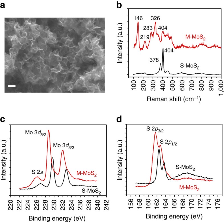
Figure 1a shows a typical scanning electron microscopic (SEM) image of the as-prepared M-MoS2 sample. The MoS2 nanosheets are 100 nm in size and a few nanometres in thickness. The morphology of S-MoS2 is similar to that of M-MoS2 on the nanoscale (Supplementary Fig. 1). The results from energy dispersive X-ray spectroscopy indicated that the S to Mo atomic ratio of the as-prepared M-MoS2 is ∼2.05 (Supplementary Fig. 2). The most notable difference between M-MoS2 and S-MoS2 is the symmetry of the sulfur in their structures. The structural variations result in significant differences in their characteristic Raman features. Figure 1b shows the Raman spectra of M-MoS2 and S-MoS2 synthesized at 200 °C and 240 °C, respectively. A strong Raman band is observed at 146 cm−1 and attributed to Mo–Mo stretching vibrations in M-MoS2. Calculations have predicted this band at the K points of the Brillouin zone for octahedrally coordinated distorted MoS2 (ref. 12). Our results confirm the existence of this band in M-MoS2. The Raman shifts (that is, ∼219, 283 and 326 cm−1) are also associated with the phonon modes in M-MoS2. S-MoS2 exhibits typical Raman shifts of ∼378 and 404 cm−1 for E12g and A1g, respectively, which are substantially different from those of M-MoS2.
Figure 1. Morphology of M-MoS2 and phase identification of M-MoS2 and S-MoS2.
(a) SEM image of M-MoS2 showing the nanosheet structures. Scale bar, 100 nm. (b) Raman shift of M-MoS2 and S-MoS2. (c,d) High-resolution X-ray photoelectron spectroscopy (XPS) spectra of Mo 3d (c) and S 2p (d) for M-MoS2 and S-MoS2.
The phase identification of the synthesized M-MoS2 and S-MoS2 was further studied using X-ray photoelectron spectroscopy and the results are shown in Fig. 1c,d. The Mo 3d spectra consist of peaks located at approximately 228.7 and 231.8 eV, which correspond to the 3d5/2 and 3d3/2 components, respectively, of Mo4+ in M-MoS2. However, the Mo 3d peaks of the M-MoS2 samples also exhibit weak shoulders at the positions as those in S-MoS2 due to the transformation of M-MoS2 in vacuum and X-ray illumination. The details for the peak deconvolution are provided in Supplementary Fig. 3 and Supplementary Note 1. The Mo 3d peaks of M-MoS2 shifted to lower binding energies by ∼1 eV with respect to the corresponding peaks in S-MoS2. This result is consistent with the previously obtained relaxation energy of 1 eV for M-MoS2 derived from S-MoS2 (refs 20, 21). Similarly, the S 2p peaks of M-MoS2 were located at ∼161.6 and 162.7 eV, and associated with S 2p3/2 and 2p1/2, respectively, which are also ∼1 eV lower than the corresponding peaks in S-MoS2. It is important to note that the prominent S peak located at ∼168 eV was absent, indicating that the sulfur atoms remain unoxidized in M-MoS2. However, this peak was observed in S-MoS2 after annealing at 240 °C.
Morphologies and optical properties of MoS2
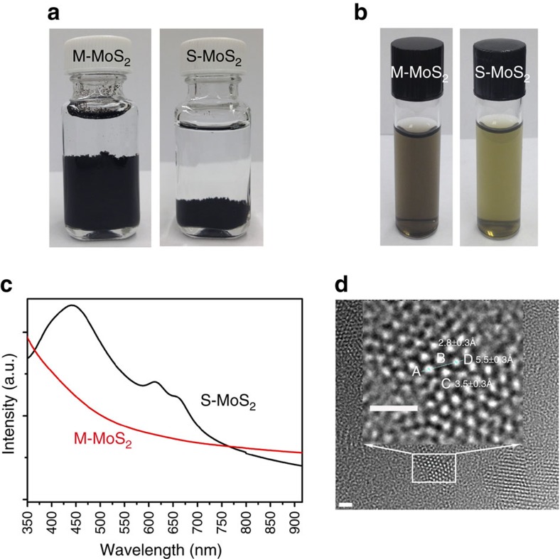
Figure 2a shows optical images of the two types of MoS2 dispersed in water. M-MoS2 does not appear to exhibit bulk aggregation, whereas S-MoS2 aggregates at the bottom of the solution. This result may be because M-MoS2 possesses hydrophilic surfaces, whereas S-MoS2 possesses relatively hydrophobic surfaces5,22. After sonication, both M-MoS2 and S-MoS2 can uniformly disperse in water (Fig. 2b). However, M-MoS2 was grey colour, whereas S-MoS2 was green colour. These colours were associated with their optical properties, which were confirmed by optical absorption spectroscopy. Figure 2c shows the ultraviolet–visible absorption spectra of M-MoS2 and S-MoS2 in water. Two typical absorption peaks located at 613 and 660 nm were observed for S-MoS2 and these peaks are associated with the energy split from the valence band spin–orbital coupling in S-MoS2 with large lateral dimensions23. In addition, another optical absorption band located at ∼442 nm was observed. This band most probably results from the quantum effect of smaller lateral-sized S-MoS2 nanosheets. The absorption spectrum of M-MoS2 has no salient absorption bands but a monotonic change that is indicative of its metallic property.
Figure 2. Morphology and property of M-MoS2 and S-MoS2.
(a) As-prepared M-MoS2 and S-MoS2 in water. (b) Suspension of M-MoS2 and S-MoS2 in water. (c) Ultraviolet–visible absorption of M-MoS2 and S-MoS2. (d) HRTEM image of M-MoS2. The region indicated by the squares is enlarged to show the atomic structure of M-MoS2. Scale bar, 1 nm.
The atomic structure of M-MoS2 was investigated using a high-resolution scanning transmission electron microscope (HRTEM) at different magnifications (Supplementary Fig. 4) and the high-magnification image is shown in Fig. 2d. The hexagonal atomic arrangement of Mo indicates that each individual nanosheet consists of single crystal domains. Mo atoms on the basal plane have a Mo–Mo distance from A to D of 5.5±0.3 Å, A to B of 2.8±0.3 Å and A to C of 3.5±0.3 Å. However, the crystal lattice may convert into an amorphous structure under the high-energy electron beam of TEM as observed by Lukowski et al.2.
Stability of the M-MoS2
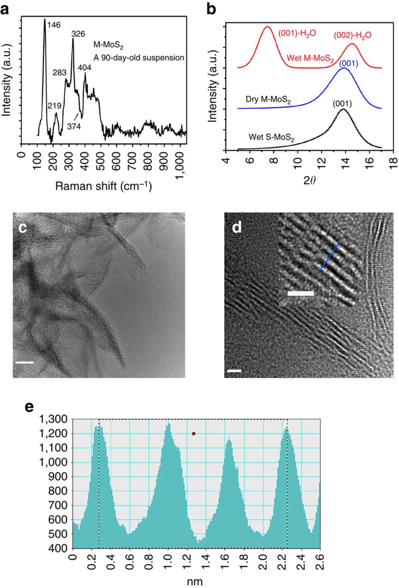
The as-prepared M-MoS2 nanosheets in water exhibited good stability over time. We believe that the high purity of M-MoS2 plays an important role in its stability. 1T-MoS2 (metallic phase), which was derived from 2H-MoS2 (semiconductor phase), consists of electronic heterostructures of 2H-MoS2 and 1T-MoS2 in individual layers of MoS2 (ref. 9). The coexistence of semiconductor MoS2 with a metallic phase in a single layer resulted in an expedited transformation of 1T back to 2H MoS2. Therefore, the structure was reported to be stable for 12 days with the observation of the 2H structure in water for chemically exfoliated MoS2 (ref. 12). The samples obtained in this study were stored in water for more than 90 days at room temperature and no obvious change in the Raman shift was observed (Fig. 3a). The characteristic peaks of the stored M-MoS2 were similar to those observed for the freshly prepared samples. This observation indicates that the as-prepared M-MoS2 was highly stable in water. It is important to note that a traceable transformation of M-MoS2 to S-MoS2 may occur, as suggested by the very weak shoulder at 374 cm−1. The pure metallic phase in the individual layers contributes to the stability of the material. A comparison of the Raman spectra of M-MoS2 stored under different conditions and S-MoS2 is shown in Supplementary Fig. 5.
Figure 3. Raman and structural characterization to investigate the stability of M-MoS2.
(a) Raman shift of M-MoS2 stored for 90 days at room temperature. (b) XRD patterns of wet M-MoS2, dry M-MoS2 and wet S-MoS2. (c) Low-resolution TEM image of M-MoS2. Scale bar, 10 nm. (d) HRTEM image of M-MoS2. The region indicated by the square is enlarged to show the layered structure of M-MoS2. Scale bar, 2 nm. (e) Line scan of the HRTEM image indicated by the blue line in d, indicating a layer-to-layer spacing of 0.65 nm.
Another possible stability mechanism may arise from the monolayer of water molecules that was adsorbed on both sides of the M-MoS2 nanosheets. This layer prevents aggregation and stacking, and maintains the octahedral structure in M-MoS2. The existence of the water molecule layer was confirmed by XRD measurements (Fig. 3b). The peak at 7.5°, which corresponds to a spacing of 11.8 Å, was identified as (001)-H2O for M-MoS2-H2O, which contains a bilayer of water molecules between the adjacent layers of MoS2 nanosheets24. As the layer thickness of MoS2 was ∼6.2 Å and the thickness of a monolayer of water was 2.8 Å, the total thickness of a MoS2 layer surrounded by a water bilayer would be 11.8 Å. This result was previously confirmed by XRD25. The peak located at 14.6° was assigned to the second-order reflection of M-MoS2-H2O.
XRD was also performed on the M-MoS2 nanosheets after they were dried for 24 h in a vacuum chamber at a pressure of 6 mTorr. The XRD pattern of the dried M-MoS2 is similar to that of S-MoS2 with a peak at 13.88° (Fig. 3b), which corresponds to the stacked M-MoS2 multilayers. This result suggests that the spacing between the Mo planes for M-MoS2 was 6.4±0.1 Å. This spacing is larger than that of bulk MoS2 (that is, 6.15 Å). The diffraction peak at 7.5° disappeared due to desorption of the water molecules on the nanosheet surfaces. The TEM and HRTEM images indicate that M-MoS2 was composed of single-layer or several-layer structures (Fig. 3c,d). The lattice fringe spacing of M-MoS2 was measured to be 1.97 nm for a four-layer nanosheet, which produced a Mo–Mo spacing of 6.5±0.1 Å (Fig. 3e). This result is consistent with the value obtained from the XRD measurements. The increased interlayer spacing in M-MoS2 may contribute to its stability due to the weakened S–S van der Waals interactions and reduced restacking probability.
M-MoS2 contained adsorbed water molecules, which was confirmed by XRD measurements. However, this phenomenon was not observed in S-MoS2 nanostructures. This difference between the two phases of MoS2 reflects the different surface properties (that is, M-MoS2 is hydrophilic, whereas S-MoS2 is hydrophobic). These properties are determined by the atomic structures of M-MoS2 and S-MoS2. The Mo atom in M-MoS2 is located in an octahedral S coordination, whereas the Mo atom in S-MoS2 coordinated by six S atoms in a trigonal prismatic arrangement with S acting as a hydrophobic site and Mo serving as a hydrophilic site26. These different surface properties were also observed regardless of whether they were dispersed in water or deposited as thin films on substrates (Supplementary Fig. 6). Contact angle measurements were conducted on both the M-MoS2 and S-MoS2 films. A contact angle of 25° was observed for M-MoS2 and an angle of 118° was determined for S-MoS2, confirming the highly hydrophilic surface of M-MoS2. The details are provided in Supplementary Fig. 7.
Metallic phase MoS2 for HER
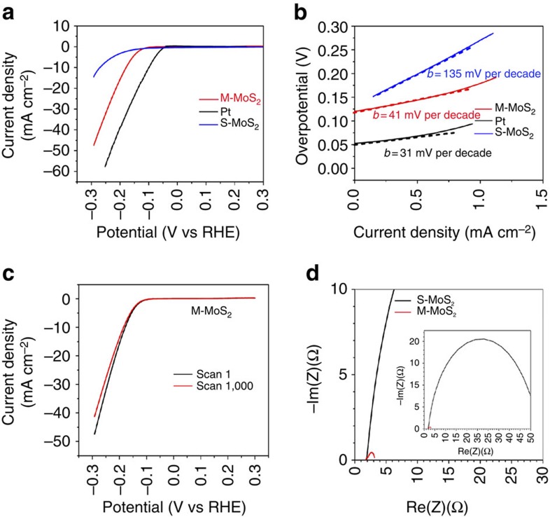
The different surface properties, atomic structure and morphology of M-MoS2 and S-MoS2 on substrates led to significant differences in the HER. Hydrogen production measurements were conducted for the M-MoS2 and S-MoS2 nanosheets deposited on glassy carbon electrodes using a three-electrode cell in a 0.5-M sulfuric acid electrolyte. Figure 4a,b show the polarization curves and corresponding Tafel plots of the M-MoS2 and S-MoS2 nanosheets compared with those of Pt. It is important to note that the Tafel plot employs a logarithmic current density axis. A low potential of −175 mV at a current density of 10 mA cm−2 and a Tafel slope of 41 mV per decade were obtained for M-MoS2. This observed potential for hydrogen production represents the lowest value among the reported experimental data for the use of only MoS2 materials. The long-term stability of the M-MoS2 electrode for the HER was investigated. After 1,000 cycles of continuous operation, the exfoliated MoS2 nanosheets exhibited <12% decay in the electrocatalytic current density (Fig. 4c). The advantage of using M-MoS2 nanosheets becomes more apparent through electrochemical impedance spectroscopy analysis. The electrochemical impedance spectroscopy was performed under the HER conditions. The Nyquist plots are shown in Fig. 4d and revealed a dramatically decreased charge transfer resistance for the M-MoS2 nanosheets (∼1 Ω) relative to the S-MoS2 nanosheets (∼50 Ω). Furthermore, we measured the resistivity of the M-MoS2 (300 nm thick) and S-MoS2 (340 nm thick) films using a four-probe method under ambient conditions. The sheet resistances are 1.61 × 10⁴ Ω/□ for M-MoS2 and 2.26 × 10⁹ Ω/□ for S-MoS2, which correspond to a resistivity of 0.482 Ω·cm for M-MoS2 and 7.68 × 10⁴ Ω·cm for S-MoS2. This result indicates that M-MoS2 has a conductivity that is five orders of magnitude higher than that of S-MoS2.
Figure 4. HER activity of the synthesized MoS2 nanosheets.
(a) Polarization curves of the M-MoS2 and S-MoS2 nanosheets. (b) Corresponding Tafel plots obtained from the polarization curves. The Tafel slopes were ∼41 and ∼135 mV per decade for M-MoS2 and S-MoS2, respectively. (c) Polarization curves of the M-MoS2 nanosheets after 1 and 1,000 cycles of continuous operation. (d) Nyquist plots of M-MoS2 and S-MoS2.
It is important to note that the growth of M-MoS2 and the HER measurements are highly reproducible. The growth process of M-MoS2 failed only once in 96 trials. The failure was caused by washing the autoclave with HNO3 and we believe that a trace amount of residual HNO3 may have oxidized the products via different chemical reactions. The autoclave was typically cleaned by sonication in water. We have performed the HER 62 times using our synthesized M-MoS2 and all of the trials yielded results similar to those shown in Fig. 4a,b. The exceptional performance of M-MoS2 for hydrogen production may be due to the high purity, dense active sites, good conductivity and excellent hydrophilic property of M-MoS2. By contrast, S-MoS2 exhibited little HER activity with a potential of −274 mV at 10 mA cm−2 and a Tafel slope of 135 mV per decade. The poor performance of S-MoS2 in the HER was due to few active sites, aggregation and its hydrophobic surface. The exchange current density of M-MoS2, S-MoS2 and Pt is discussed in Supplementary Discussion. Although M-MoS2 still lags behind Pt, improvement in the HER activity can be accomplished by enhancing the conductivity of the nanoscale M-MoS2. Therefore, metallic MoS2 exhibits great potential for use as a replacement for Pt in the HER as a low-cost and highly active catalyst for practical applications.
Discussion
The mechanism underlying the formation of the stable metallic phase of MoS2 is directly associated with the weak reducer urea, which can precisely and effectively reduce MoO3 to M-MoS2 as shown in equation (1). The absence of a urea reducer while maintaining other growth conditions would result in a product dominated by amorphous MoS3, as shown in equation (2) (see Supplementary Methods and Supplementary Fig. 8). Other reducers, such as hydrazine, reduce MoO3 to S-MoS2 only due to the relatively strong electron donating ability of hydrazine.
 |
 |
 |
During the synthesis of M-MoS2, the three most important factors are solvent, pH and temperature. First, water serves as a solvent and is adsorbed on the surface of M-MoS2 to form a water molecular layer that prevents layer stacking. When an organic solvent, such as ethanol or dimethylformamide, was added to the reaction, no desirable product was produced (see the Supplementary Methods and Supplementary Fig. 9). No solid product was found in the autoclave when a 1:1 ratio of water to ethanol was used. Second, the pH controls the steric structure of the starting materials and the formation of M-MoS2. When the pH value was ≤4, the octahedral coordination of MoO3 can be maintained, which may lead to the formation of M-MoS2. At higher pH values (pH 8) achieved through the addition of ammonia, the MoO3 structure converts into MoO42− tetrahedral centres. This change causes the reaction to yield no desirable products. Third, the temperature also plays a key role in the formation of M-MoS2. In this study, pure M-MoS2 was obtained at 200 °C and S-MoS2 was formed at 240 °C in the reaction listed in equation (3).
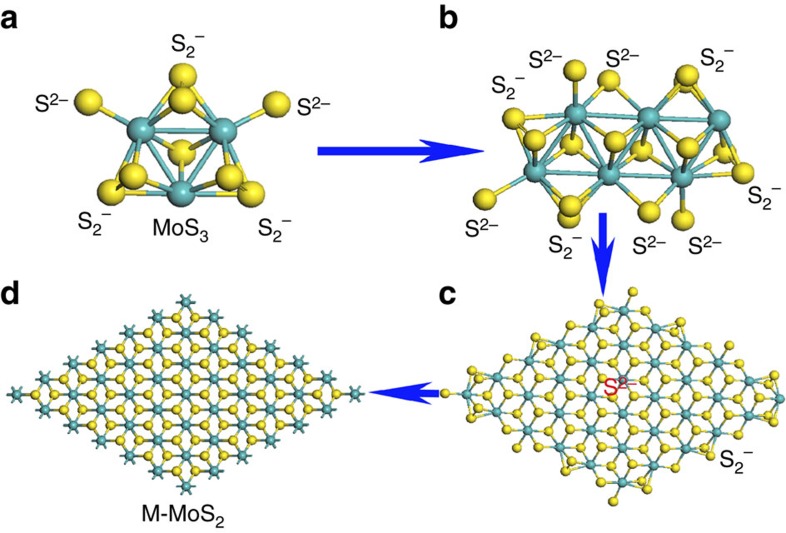
Based on these discussions, the metastable M-MoS2 intermediate can be formed and stabilized in a pressurized hydrothermal process with a suitable reducer and temperature. The proposed mechanism involves the formation of a crystal phase of M-MoS2 from amorphous clustered MoS3 with S2− edge bonds reduced by urea. In fact, many investigations have revealed the structural evolution from MoS3 to S-MoS2 without the MoS2 metallic phase during the evolution process27,28,29. We believe that the high temperature and strong reducer used in the previous studies may have only resulted in the formation of semiconductor MoS2. This result was also confirmed in this study, because only S-MoS2 was obtained when the temperature was increased to 240 °C. The evolution process for the formation of M-MoS2 is shown in Fig. 5, which illustrates the growth of MoS3 from one cluster to two and finally to a nanosheet. The central part possesses the structure of M-MoS2 and the S2− bond on the edge can be removed by urea to continue the growth to form a single layer of M-MoS2 (ref. 30). A control experiment was carried out by stopping the growth after 90 min, which resulted in a mixture of MoS3 and M-MoS2 in the solution. The existence of MoS3 and its corresponding peak at 120 cm−1 peak was confirmed by Raman spectroscopy31. Furthermore, a Raman band located at 548 cm−1, which was due to the S2− stretching vibration in MoS3, was observed. Energy dispersive X-ray spectroscopy measurements indicate a ratio of 1:3 for Mo and S (See Supplementary Fig. 10b). The Mo–Mo vibration mode at 146 cm−1 starts to appear and become more prominent as growth time increased, indicating the transformation of MoS3 to M-MoS2 (see Supplementary Fig. 10c). After continuing the reaction for 6 h, only M-MoS2 was observed in the product. At this point, the Raman peak located at 120 cm−1 disappeared and the intensity of the 146 cm−1 peak reached its maximum. This result indicates the complete conversion of MoS3 to M-MoS2.
Figure 5. Schematic illustrations of the evolution process of M-MoS2 from MoS3.
(a) One MoS3 cluster with S2− and S2−. (b) Combination of two MoS3 clusters with the breaking of S2−. (c) Several MoS3 cluster forming MoS2 with S2− in the centre and MoS3 with S2− at the edge. (d) Stable M-MoS2 crystal structure.
A hydrothermal process has been used to grow S-MoS2. To the best of our knowledge, the preparation of M-MoS2 using a hydrothermal method has not been previously reported. We believe that the growth conditions used in this study play a key role in the formation and stabilization of M-MoS2. M-MoS2 is an unstable phase that can easily transform to S-MoS2. Therefore, the octahedral coordination of M-MoS2 must be maintained during deposition. For this reason, we used MoO3 as the starting material, because it possesses the same octahedral structure as M-MoS2. The metallic phase can be obtained when the crystal structure can be maintained during the conversion process from MoO3 to MoS2. Urea, which is a weak reducer, is able to maintain the crystal structure at a low pH value and optimum temperature (200 °C) for hydrothermal growth. As mentioned in the previous sections, only S-MoS2 was obtained at a higher growth temperature of 240 °C, because the octahedral structure of M-MoS2 cannot be maintained under the growth conditions used. Once the M-MoS2 nanosheets were formed at 200 °C, the adsorption of water molecules on their surfaces due to the hydrophilic nature of the surface provides an environment to maintain the octahedral structure and preventing restacking of the layers. Therefore, M-MoS2 can be stored in water for several months without significant transition to S-MoS2. However, once M-MoS2 is removed from water and dried in a vacuum, it will slowly convert to S-MoS2. This observation indicates that the stability of M-MoS2 is dependent on the environment. Although this study was focused on the influence of water, the environmental stability of M-MoS2 under other conditions, such as different gases and solutions other than water, should be considered in future investigations.
In conclusion, highly pure and stable M-MoS2 nanosheets were synthesized in solution using a rational and controllable approach. A unique Raman peak located at 146 cm−1 due to M-MoS2 was experimentally observed, which confirms the theoretical prediction. A growth mechanism was proposed and is supported by the experimental data. Excellent activity of M-MoS2 for the HER was achieved and the material has the potential to replace Pt in practical applications. These results provide opportunities for studying the metallic phase of MoS2, which has potential technological applications in renewable energy, energy storage and heterogeneous catalysis.
Methods
Preparation of M-MoS2 and S-MoS2
MoO3 powder (CAS number is 1311-27-5) and urea (CAS number is 57-13-6) were purchased from the Sigma-Aldrich Company. Thioacetamide (CAS number is 62-55-5) was purchased from the Fisher Scientific Company. The autoclave (model number 4749) was ordered from the Parr Instrument Company.
Twelve milligrams of MoO3, 14 mg of thioacetamide and 0.12 g of urea were dissolved in 10 ml of deionized water and stirred for 2 h. Then, the solution was placed in an autoclave and loaded into a furnace (from MTI), which has been heated to 200 °C. The temperature of the oven was maintained at 200 °C for 12 h. Next, the reaction was terminated by rapidly cooling the solution to room temperature by removing the autoclave from the oven. The prepared M-MoS2 was collected and washed with deionized water several times, followed by storage in deionized water before use. The same procedure was used to synthesize S-MoS2 at 240 °C. Two-dimensional nanosheets were observed and no significant difference was observed between M-Mo2 and S-MoS2 based on their nanoscale morphology.
Ultraviolet–visible–infrared spectroscopy
Ultraviolet–visible–infrared absorption spectroscopy of the M-MoS2 and S-MoS2 dispersions in water were recorded using a Perkin Elmer Lambda 25 spectrophotometer.
TEM observations
TEM and HRTEM images and electron diffraction were performed on a FEI Tecnai G2 F20 S-Twin microscope operated at an accelerating voltage of up to 200 kV. The TEM samples were prepared by sonication at 500 W for ∼5 min and 25 μl of the supernatant were dropped onto holey carbon grids.
SEM observations
The SEM images were obtained using a field-emission gun SEM (Quanta 400 FEG FEI). The samples were dispersed in water and then dropped onto the Si/SiO2 substrates.
X-ray photoelectron spectroscopy
X-ray photoelectron spectroscopy was conducted using an Axis Ultra DLD (Kratos) system. The vacuum of the chamber was 1 × 10⁻⁹ Torr. A monochromatic aluminum Kα source with a source power of 150 W (15 kV × 10 mA) was used. The pass energy was 160 eV for wide scans and 40 eV for narrow scans.
Raman spectroscopy
Raman spectroscopy was performed using a LabRam HR800 UV NIR and 532-nm laser excitation with working distances on a × 50 lens. The Raman spectra of M-MoS2 and S-MoS2 were recorded by depositing the samples on silicon substrates.
XRD patterns
The XRD patterns of M-MoS2 and S-MoS2 were recorded for two theta values ranging from 4° to 18°, to characterize the interlayer spacing. The characterization was performed on a Bruker AXS-D8 Advance powder X-ray diffractometer using Cu/Ka radiation (λ=1.5406 Å) with a step size of 0.02° and a dwell time of 3.0 s.
Electrocatalytic hydrogen evolution
The electrochemical measurements were performed using a three-electrode electrochemical station (Gamry Instruments). All of the measurements were performed in a solution consisting of 50 ml of a 0.5-M H2SO4 electrolyte prepared using 18 M deionized water purged with H2 gas (99.999%). The MoS2 suspension in water was dropped onto glassy carbon as the working electrode. All of the working electrodes were prepared using the MoS2 solutions. The solution concentrations of M-MoS2 and S-MoS2 were ∼0.3 mg ml−1 and ∼0.4 mg ml−1, respectively, in water. The diameter of the glass carbon electrode was 0.3 cm and the area was ∼0.07 cm2. The amount of deposited catalyst on the electrode was ∼ 43 μg cm−2 for M-MoS2 and 114 μg cm−2 for S-MoS2. Platinum foil was used as the counter electrode and a saturated calomel was used as the reference electrode. The reversible hydrogen electrode was calibrated using platinum as both the working and counter electrodes to +0.3 V versus the saturated calomel reference electrode. The performance of the hydrogen evolution catalyst was measured using linear sweep voltammetry from +0.3 to −0.3 V versus reversible hydrogen electrode with a scan rate of 5 mV s−1.
Additional information
How to cite this article: Geng, X. et al. Pure and stable metallic phase molybdenum disulfide nanosheets for hydrogen evolution reaction. Nat. Commun. 7:10672 doi: 10.1038/ncomms10672 (2016).
Supplementary Material
Supplementary Figures 1-10, Supplementary Note 1, Supplementary Discussion and Supplementary Methods
Acknowledgments
This work was supported by the National Science Foundation of US (Award Number EPS-1003970) and the NASA RID programme. We thank Dr Allan Thomas for discussions on the electrochemical impedance spectroscopy measurements. We thank the Center for Integrative Nanotechnology Sciences at the UALR for experimental assistance.
Footnotes
Author contributions X.G., T.C. and J.C. conceived and designed the experiments. X.G. and J.C wrote the paper with input from all of the authors. B.C. edited the manuscript. All of the experimental work was conducted by X.G with W.W., W.S., A.A., M.B., H.Z., F.W. and J.C. The experimental data were analysed by X.G. with J.C. and T.C., and the results were discussed by all of the authors.
References
- Eda G. et al. Photoluminescence from chemically exfoliated MoS2. Nano Lett. 11, 5111–5116 (2011). [DOI] [PubMed] [Google Scholar]
- Lukowski M. A. et al. Enhanced hydrogen evolution catalysis from chemically exfoliated metallic MoS2 nanosheets. J. Am. Chem. Soc. 135, 10274–10277 (2013). [DOI] [PubMed] [Google Scholar]
- Voiry D. et al. Conducting MoS2 nanosheets as catalysts for hydrogen evolution reaction. Nano Lett. 13, 6222–6227 (2013). [DOI] [PubMed] [Google Scholar]
- Bai S., Wang L., Chen X., Du J. & Xiong Y. Chemically exfoliated metallic MoS2 nanosheets: a promising supporting co-catalyst for enhancing the photocatalytic performance of TiO2 nanocrystals. Nano Res. 8, 175–183 (2015). [Google Scholar]
- Acerce M., Voiry D. & Chhowalla M. Metallic 1T phase MoS2 nanosheets as supercapacitor electrode materials. Nat. Nanotechnol. 10, 313–318 (2015). [DOI] [PubMed] [Google Scholar]
- Py M. A. & Haering R. R. Structural destabilization induced by lithium intercalation in MoS2 and related compounds. Can. J. Phys. 61, 76–84 (1983). [Google Scholar]
- Mattheiss L. F. Band structures of transition-metal–dichalcogenide layer compounds. Phys. Rev. B 8, 3719–3740 (1973). [Google Scholar]
- Zheng J. et al. High yield exfoliation of two-dimensional chalcogenides using sodium naphthalenide. Nat. Commun. 5, 2995 (2014). [DOI] [PubMed] [Google Scholar]
- Eda G. et al. Coherent atomic and electronic heterostructures of single-layer MoS2. ACS Nano 6, 7311–7317 (2012). [DOI] [PubMed] [Google Scholar]
- Heising J. & Kanatzidis M. G. Structure of restacked MoS2 and WS2 elucidated by electron crystallography. J. Am. Chem. Soc. 121, 638–643 (1999). [Google Scholar]
- Chou S. S. et al. Controlling the metal to semiconductor transition of MoS2 and WS2 in solution. J. Am. Chem. Soc. 137, 1742–1745 (2015). [DOI] [PubMed] [Google Scholar]
- Jiménez Sandoval S., Yang D., Frindt R. F. & Irwin J. C. Raman study and lattice dynamics of single molecular layers of MoS2. Phys. Rev. B 44, 3955–3962 (1991). [DOI] [PubMed] [Google Scholar]
- Calandra M. Chemically exfoliated single-layer MoS2: stability, lattice dynamics, and catalytic adsorption from first principles. Phys. Rev. B 88, 245428 (2013). [Google Scholar]
- Güller F., Llois A. M., Goniakowski J. & Noguera C. Prediction of structural and metal-to-semiconductor phase transitions in nanoscale MoS2, WS2, and other transition metal dichalcogenide zigzag ribbons. Phys. Rev. B 91, 075407 (2015). [Google Scholar]
- Liang Y. et al. Rechargeable Mg batteries with graphene-like MoS2 cathode and ultrasmall Mg nanoparticle anode. Adv. Mater. 23, 640–643 (2011). [DOI] [PubMed] [Google Scholar]
- Feldman Y., Wasserman E., Srolovitz D. J. & Tenne R. High-rate, gas-phase growth of MoS2 nested inorganic fullerenes and nanotubes. Science 267, 222–225 (1995). [DOI] [PubMed] [Google Scholar]
- Enyashin A. N. et al. New route for stabilization of 1T-WS2 and MoS2 phases. J. Phys. Chem. C. 115, 24586–24591 (2011). [Google Scholar]
- Lin Y. C., Dumcenco D. O., Huang Y. S. & Suenaga K. Atomic mechanism of the semiconducting-to-metallic phase transition in single-layered MoS2. Nat. Nanotechnol. 9, 391–396 (2014). [DOI] [PubMed] [Google Scholar]
- Nayak A. P. et al. Pressure-induced semiconducting to metallic transition in multilayered molybdenum disulphide. Nat. Commun. 5, 3731 (2014). [DOI] [PubMed] [Google Scholar]
- Kappera R. et al. Phase-engineered low-resistance contacts for ultrathin MoS2 transistors. Nat. Mater. 13, 1128–1134 (2014). [DOI] [PubMed] [Google Scholar]
- Wang H. et al. Electrochemical tuning of vertically aligned MoS2 nanofilms and its application in improving hydrogen evolution reaction. Proc. Natl Acad. Sci. USA 110, 19701–19706 (2013). [DOI] [PMC free article] [PubMed] [Google Scholar]
- Lee J. et al. Two-dimensional layered MoS2 biosensors enable highly sensitive detection of biomolecules. Sci. Rep. 4, 7352 (2014). [DOI] [PMC free article] [PubMed] [Google Scholar]
- Mak K. F., Lee C., Hone J., Shan J. & Heinz T. F. Atomically thin MoS2: a new direct-gap semiconductor. Phys. Rev. Lett. 105, 136805 (2010). [DOI] [PubMed] [Google Scholar]
- Joensen P., Crozier E. D., Alberding N. & Frindt R. F. A study of single-layer and restacked MoS2 by x-ray diffraction and x-ray absorption spectroscopy. J. Phys. C: Solid State Phys. 20, 4043–4053 (1987). [Google Scholar]
- Qin X. R. Scanning Tunneling Microcopy of Layered Materials (PhD Thesis. Simon Fraser Univ., (1992). [Google Scholar]
- Farimani A. B., Min K. & Aluru N. R. DNA base detection using a single-layer MoS2. ACS Nano 8, 7914–7922 (2014). [DOI] [PubMed] [Google Scholar]
- Liu K.K. et al. Growth of large-area and highly crystalline MoS2 thin layers on insulating substrates. Nano Lett. 12, 1538–1544 (2012). [DOI] [PubMed] [Google Scholar]
- Koroteev V. O., Bulusheva L. G., Okotrub A. V., Yudanov N. F. & Vyalikh D. V. Formation of MoS2 nanoparticles on the surface of reduced graphite oxide. Phys. Stat. Solid. B 248, 2740–2743 (2011). [Google Scholar]
- Liao L. et al. MoS2 formed on mesoporous graphene as a highly active catalyst for hydrogen evolution. Adv. Funct. Mater. 23, 5326–5333 (2013). [Google Scholar]
- Diemann E., Weber T. & Muller A. Modeling the thiophene HDS reaction on a molecular level. J. Catal. 148, 288–303 (1994). [Google Scholar]
- Chang C. H. & Chan S. S. Infrared and raman studies of amorphous MoS3 and poorly crystalline MoS2. J. Catal. 72, 139–148 (1981). [Google Scholar]
Associated Data
This section collects any data citations, data availability statements, or supplementary materials included in this article.
Supplementary Materials
Supplementary Figures 1-10, Supplementary Note 1, Supplementary Discussion and Supplementary Methods


