

Abstract
Objective
Single carbon fiber electrodes (d=8.4 μm) insulated with parylene-c and functionalized with PEDOT:pTS have been shown to record single unit activity but manual implantation of these devices with forceps can be difficult. Without an improvement in the insertion method any increase in the channel count by fabricating carbon fiber arrays would be impractical. In this study, we utilize a water soluble coating and structural backbones that allow us to create, implant, and record from fully functionalized arrays of carbon fibers with ~150 μm pitch.
Approach
Two approaches were tested for the insertion of carbon fiber arrays. The first method used a PEG coating that temporarily stiffened the fibers while leaving a small portion at the tip exposed. The small exposed portion (500 μm – 1 mm) readily penetrated the brain allowing for an insertion that did not require the handling of each fiber by forceps. The second method involved the fabrication of silicon support structures with individual shanks spaced 150 μm apart. Each shank consisted of a small groove that held an individual carbon fiber.
Main results
Our results showed that the PEG coating allowed for the chronic implantation of carbon fiber arrays in 5 rats with unit activity detected at 31 days post-implant. The silicon support structures recorded single unit activity in 3 acute rat surgeries. In one of those surgeries a stacked device with 3 layers of silicon support structures and carbon fibers was built and shown to readily insert into the brain with unit activity on select sites.
Significance
From these studies we have found that carbon fibers spaced at ~150 μm readily insert into the brain. This greatly increases the recording density of chronic neural probes and paves the way for even higher density devices that have a minimal scarring response.
1. Introduction
The ability to record simultaneous neural activity from large neuronal populations has had a far reaching impact in the fields of neuroscience [1,2] and neural prosthetics, including brain machine interfaces (BMIs) [3–5]. These fields often employ the use of microelectrode arrays (MEAs) which can routinely record from dozens to several hundred electrodes simultaneously. MEAs are typically composed of silicon shanks, ideally at regular and closely spaced intervals, with one or more electrode recording sites on the individual shanks. Some of the earliest, and still widely used, MEAs are microwire arrays consisting of individually placed wires, typically arranged in a linear configuration [1,6–8]. Other commonly used high channel MEAs include the Michigan probe [9–11] and Utah array [12–14]. While extremely popular in their use, all of these MEAs, and their respective applications, would benefit from greater spatial sensitivity with more closely spaced electrode shanks that can record from more neurons, damage less tissue, and last for decades.
A limiting factor in creating extremely high density arrays, particularly those that can be implanted long-term, is gliosis. The initial trauma endured by the brain tissue and local vasculature upon probe insertion [15–17] can recover rapidly if the foreign object is either removed [18,19] or dissolves away [20]. However, when a probe is chronically implanted a persistent reactive response will take place. This reactive response is best characterized by a glial sheath or scar, surrounding the probe, composed of activated astrocytes and microglia [18,21–31]. This scar can extend out to 250 μm for a typical 15 μm thick silicon shank electrode [18]. In addition, the chronic glial sheath contributes to a local zone of neuronal cell death and neurofilament loss (~100 – 200 μm radius) making it difficult to acquire signal [18]. Coupled with the reactive response is the persistence of leaky vasculature. An implanted neural probe continually disrupts local vasculature due to micromotion and mechanical strain [31,32] leading to the constant release of inflammatory agents [18,20,26,28,30,33–35] that perpetuates the local reactive response (see [36] for review). Thus, an MEA with a shank pitch of less than 400 μm would begin to suffer from overlapping regions of glial scarring, neuronal death, and leaky vasculature, ultimately leading to degraded probe performance in a continuous scarred region.
The overall shortcomings of traditional MEAs have led to many groups exploring various design modifications. Some have tried to develop electrodes with a low Young's modulus by building the electrodes from ultra-soft composite blend polymers*, soft-nanocomposites [37,38], shape memory polymers [39], parylene-c [40,41], polyimide [42], or polydimethyl siloxane [43,44]. These materials have a Young's modulus that is closer to that of the brain; however, these new probes introduce new challenges due to bending, buckling, and deflecting of the probe during insertion. In addition, these polymer probes use thin-film metal traces which are brittle and geometries that are more susceptible to cracking during fabrication, assembly, and insertion [45,46]. To compensate for the softness of the probe and fragility of the traces, these softer probes often reinforce their structures by using larger dimensions, which can lead to greater tissue damage and also greatly diminishes their ability to be used in a high density electrode array.*
Another approach has been the development of ultrasmall probes. Skousen and colleagues showed that a lattice style electrode, with its greatly reduced surface area, had significantly improved normalized neuronal density (~90%) within a 50 μm radius, compared to a solid device (~40%) with the same footprint [47]. This type of electrode design demonstrates the ability to minimize the scarring response of the brain which in turn would allow for MEAs that have shank pitches much smaller than 400 μm. Many current designs require the use of a shuttle [44,48] or lattice style backbone [47,49] that can make implantation difficult and possibly lead to a larger damage radius. In addition, many of these smaller devices cannot reach deeper structures in the brain, can be extremely brittle, and are difficult to achieve in high channel counts across large cortical areas compared to state-of-the-art MEAs.
Ideally an MEA would be made from a soft material that can be manufactured with ultrasmall dimensions with sufficient strength and durability, and have high channel counts. Unfortunately, such a device does not currently exist due to the physical limitations and tradeoffs between size and strength. Our group has taken a different approach by utilizing stiff carbon fiber electrodes, which typically have radii on the order of 6 – 7 μm and a Young's modulus of 241 GPa [50], as compared to silicon's 165 GPa [51]. Some of the earliest carbon fiber electrodes were insulated in a pulled glass capillary tube, which was then back filled with an electrolyte [52]. Once insulated, this electrode can be used as is for acute electrophysiology recordings [52]. Coupled with voltammetry methods the same carbon fiber electrodes can be used to detect dopamine, or other oxidisable neurotransmitters [53], in both animals [54–56] and slice work [57,58]. These applications are feasible due to the low electrical resistivity of carbon fibers. This leads to less thermal noise and enables the fibers to detect small signals without noise contamination [53]. These characteristics have led other groups to develop and chronically implant bundled carbon fiber electrodes that form a hexadectrode-bundle, with an overall cross-sectional width of 26 μm [59].
Unfortunately, none of the previously described implementations of carbon fiber electrodes take advantage of all of the unique properties inherent to an individual fiber. The naturally small cross-sectional footprint of individual carbon fibers leads to less scarring, at a two week time point, and the high Young's modulus makes insertion easier [60]. The high Young's modulus would seem to contradict previous findings; however, the combined metrics of the small footprint and Young's modulus give our probes one of the smallest overall stiffness factors among implantable electrodes which is well documented by Kozai et al. [60]. Instead of the traditional means of insulating the carbon fibers with a glass capillary, which is brittle and can easily break, our group has insulated the devices with parylene-c, an FDA compliant material [61]. This allows the fibers to retain their flexibility or low stiffness while also maintaining their small size.
In this paper we evaluate methods to successfully insert high density carbon fiber arrays with site distances of approximately 150 μm, which to our knowledge is the smallest recorded electrode shank pitch for an MEA used in a successful chronic recording. Initially, the carbon fiber spacing negated our ability to insert each fiber individually without causing damage to neighboring sites. This problem was solved with the encapsulation of fibers in a temporary poly(ethylene glycol) (PEG) coating. While the PEG encapsulation step was sufficient for the insertion of arrays with only one or two rows of fibers, it was difficult to extend this method to arrays with three or more rows of fibers, which would allow for greater neuronal sampling within a given cortical area. Hence, a second approach using a stackable silicon support structure was developed, utilizing design cues from the PEG coated arrays, to enable the fabrication and insertion of arrays with three or more rows. With this new method, single and triple layer devices were fabricated, successfully inserted, and able to record single unit activity in acute surgical preparations.
2. Materials & Methods
2.1. Carbon Fiber Array Fabrication and Characterization
2.1.1. Array Assembly
Custom printed circuit boards (PCBs), designed to fit Tucker-Davis Technologies ZIF headstages, were manufactured by SpeedyCircuits (Huntington Beach, CA) and designed to create a high density array of carbon fibers with a specified site pitch of 0.003” or 152.4 μm. A Hirose connecter (DF30FC-20DS-0.4V, Hirose, Simi Valley, CA) was soldered to each side of the PCB and a shroud placed over the top to conform to ZIF headstages (Tucker-Davis Technologies, Alachua, FL) (figure 1(a)). Exposed gold coated traces at the tip of the PCB (figure 1(b)) were then individually coated with a conductive silver epoxy (H20E, Epoxy Technology, Billerica, MA) (figure 1(c)) using the tip of a pulled glass capillary. A carbon fiber bundle (T-650/35 3K, Cytec Thornel, Woodland Park, NJ) was then separated into individual fibers (d=6.8 μm according to manufacturer specifications [50]), which were then cut down to lengths of approximately 6 – 7 mm. A single uninsulated fiber piece was placed on each of the silver epoxy coated traces, by hand, under a microscope (figure 1(d)). This process of coating with silver epoxy and placement of the fibers, took approximately 10 minutes for eight traces. The entire assembly was then placed in an oven to heat cure the conductive silver epoxy at 140 °C for 20 minutes. These settings are higher than the manufacturers recommended times, as the original specifications were found to be insufficient for fully curing the small amount of epoxy used. This same process was then repeated on the other side of the PCB. A small amount of insulating epoxy (353NDT, Epoxy Technology, Billerica, MA) was used to protect the trace and carbon fiber contacts (figure 1(e)). A different bake setting (~120°C for 20 minutes) was used for the insulating epoxy, as the original specifications were found to be insufficient for fully curing the small amount of epoxy used. Fibers were cut to desired lengths (figure 1(f)) using a set of surgical scissors (15003-08, Fine Science Tools, Foster City, CA) and a stereoscope equipped with a reticle.
Figure 1.

Step-by-step assembly of a carbon fiber array. (a) Bare PCB with attached Hirose connector (light blue arrow) and shroud (white arrow). Exposed gold traces highlighted in the red box undergo different processing steps which are illustrated in the drawings of (b)–(e). (b) Close up drawing of exposed gold traces from bare PCB. (c) Each trace is coated with a thin layer of silver epoxy using a pulled glass capillary pipette. Silver epoxy that bridged two traces was removed by wiping the whole board with 70% ethanol. (d) Using forceps, a single carbon fiber was placed within each trace. (e) Epoxy is placed on top of the exposed contacts to insulate and protect them from damage. (f) An image of the final product with fibers cut to their desired length.
To ensure that the initially specified site pitch was well maintained after the placement of each fiber, we imaged 6 arrays with varying numbers of fibers using a digital microscope (Dino-Lite Pro, AnMo, New Taipei City, Taiwan). Using the distance tool in ImageJ 1.48v (http://imagej.nih.gov/ij/) the distance between neighboring fibers was measured. The pitch between fibers was found to be 153.7 μm ± 1 μm (mean ± standard error of the mean, n=50 distances measured).
2.1.2. Parylene-c Coating and PEDOT:pTS Electrodeposition
Once fully assembled all carbon fiber arrays used in insertion tests and for neural recordings were coated with an 800 nm thick insulating layer of parylene-c [60] using a Parylene Deposition System 2010 (SCS Coatings, Indianapolis, IN). The amount of parylene-c precursor used was determined by the following conversion, 2 g of precursor = 1 μm thick coating. For those arrays used to record neural activity the tip of each electrode was cut to expose a small bare carbon fiber site. To lower the exposed carbon fiber's site impedance a solution of 0.01 M 3,4-ethylenedioxythiophene (483028, Sigma-Aldrich, St. Louis, MO) and 0.1 M sodium p-toluenesulfonate (152536, Sigma-Aldrich, St. Louis, MO) was electrodeposited by applying 100 pA/channel for 600 seconds to form a layer of poly(3,4-ethylenedioxythiophene):sodium p-toluenesulfonate (PEDOT:pTS) [62]. All active channels were shorted together during the electrodeposition step and the total current delivered was scaled accordingly.
2.1.3. Electrochemical Impedance Spectroscopy (EIS) and Cyclic Voltammetry (CV)
To verify all deposition and coating steps, EIS and CV measurements were taken with a PGSTAT12 Autolab (EcoChemie, Utrecht, Netherlands), controlled by vendor supplied NOVA software. For all measurements, probes were first submerged by 1 mm in a 1x phosphate buffered saline (PBS) solution (BP3994, Fisher, Waltham, MA). A stainless steel rod was used as the counter electrode and an Ag|AgCl electrode (RE-5B, BASi, West Lafayette, IN) served as the reference electrode. The stainless steel rod was chosen as the counter electrode to better match the in vivo counter electrode, a stainless steel bone screw (see section 2.2.2). EIS measurements were obtained by applying a 10 mVRMS signal from 10 Hz to 31 kHz [60]. CV measurements were obtained by sweeping between 0.8 V to −0.6 V to 0.8 V, a total of three times, at a scan rate of 1 V/s [60] to rapidly assess the changing properties of the electrodes as they went through each functionalization step. Custom Matlab (Mathworks, Natick, MA) scripts were used to determine both the charge storage capacity (CSC) by integrating the area under the CV curves and frequency specific impedance values. It is important to note that although the fibers were inserted 1 mm into the 1x PBS, all CSC calculations were performed using an area of ~36.3 μm2 as this was the final geometric surface area of the carbon fiber's recording tip. Using this value consistently for CSC calculations was done to better illustrate the changes in electrode characteristics after each processing step.
2.1.4. Accelerated Soak Test Setup
Boards with parylene-c and PEDOT:pTS coated carbon fibers had the fiber only portion submerged in 1x PBS maintained at 60 °C. At each time point the fibers were removed from the heated 1x PBS and rinsed with deionized water. Next the impedance of the fibers at 1 kHz was recorded. Once recordings were complete the assembly was returned to the heated 1x PBS.
According to works by Green et al. [62] & Hukins et al. [63], equation (1) can be used to determine simulated aging time that the fibers have undergone:
| (1) |
Where t37 is the simulated aging time at 37 °C, tT is the amount of real time that the samples have been kept at the elevated temperature, T, and Q10 is an aging factor that is equal to 2, according to ASTM guidelines for polymer aging [64]. Calculating the simulated time for tT = 1 and T = 60 °C, we find that t37 = 4.92. This value of 4.92 is our acceleration factor and all real time measurements are scaled by this amount to obtain the simulated time.
2.2. PEG Facilitated Array Insertion
2.2.1. Application of PEG Coating
The first method developed to insert carbon fibers arrays, with sufficient length to reach cortical depths, used 2050 MW PEG (295906, Sigma Aldrich, St. Louis, MO), a non-toxic material that temporarily stiffened the fibers but could be removed with the application of sterile room temperature saline or Lactated Ringer's (2B2324, Baxter, Deerfield, IL), via a syringe, over the course of 15 - 20 minutes. Carbon fiber arrays were first mounted to a micromanipulator and positioned such that the two rows of fibers were parallel to the benchtop's surface. Next, with the aid of a stereoscope, a razor blade covered in aluminum foil was inserted in between the two rows of fibers. The aluminum foil was lightly coated with sterile mineral oil (M5310, Sigma Aldrich, St. Louis, MO) and all excess oil was removed. The array was then moved such that the top row of fibers (those visible from a top-down view) were gently resting on top of the oiled aluminum surface. Once the fibers were in position, a coil of wire was wrapped around a soldering iron at 350 °F with a portion of the wire left to protrude from the tip. The tip of the wire was then used to pick up a single flake of 2050 PEG. The PEG was then allowed to fully melt at the tip of the wire. Once fully melted the liquid PEG was applied to the fibers resting on the oiled aluminum surface (figure 2(a)). After cooling the PEG easily released from the oiled surface and the array was retracted. Once clear of the razor blade the array was turned over and the same operation was performed on the bottom row of fibers.
Figure 2.

(a) Application of melted 2050 PEG (light blue arrow) using a heated wire (red arrow) while the fibers (yellow arrows) rest on a lightly oiled aluminum surface. (b) Carbon fiber array coated with solidified PEG (light blue arrows) on both sides with submillimeter exposure of the fibers (yellow arrows).
2.2.2. Surgery for Chronic Implantation of PEG Coated Carbon Fibers
Chronic implantation of carbon fiber arrays used adult male Long Evans rats (n=5) weighing 300 – 350 g. Rats were first anesthetized using 5% isoflurane (v/v) to knock-out and then 1 – 3% isoflurane (v/v) to maintain anesthesia. The head was then shaved at and around the area of the incision site. The shaved area was triple swabbed using alternating applications of betadine and 70% ethanol. Ointment was applied to the eyes to keep them from drying during surgery. Once mounted in the ear bars of the stereotax, the shaved area was swabbed one more time with betadine followed by 70% ethanol. A subcutaneous injection of lidocaine (4 mg/mL) was given at the proposed site of incision at a maximum dosage of 4 mg lidocaine per 1 kg of body weight. After incision, the skin flaps were pulled away using hemostats and the skull surface cleaned using a combination of cotton swabs and 2% hydrogen peroxide (v/v). A burr bit (19008-07, Fine Science Tools, Foster City, CA) was used to drill seven holes around the periphery of the skull for seven bone screws (19010-00, Fine Science Tools, Foster City, CA). Next, a 2 mm × 3 mm craniotomy was made over the right hemisphere's motor cortex using coordinates from a reference atlas [65]. Before resecting the dura, a layer of Kwik-Sil (World Precision Instruments, Sarasota, FL) was applied to the skull at the medial and anterior sides of the craniotomy.
Following the resection of the dura, the PEG coated carbon fiber array was brought to the surface of the brain. The exposed fibers were driven into the brain manually using the stereotactic manipulator and depth was monitored using a digital readout. The insertion of the exposed fibers took approximately 5 – 10 seconds. Once the PEG coated portion of the fibers reached the brain's surface, manual insertion was halted. Using a syringe filled with room temperature sterile Lactated Ringer's, a small portion of the PEG nearest to the brain was dissolved away while a surgical spear soaked up the PEG/Ringer's solution. The fibers were then manually driven in further, again taking 5 – 10 seconds for insertion, and more PEG dissolved away until the final target depth was reached. All of the remaining PEG was dissolved away using additional Ringer's. Additional Kwik-Sil was then applied to the skull at the lateral and posterior sides of the craniotomy forming a barrier around the craniotomy. Once the Kwik-Sil had completely cured, the craniotomy, exposed fibers, and surrounding Kwik-Sil barrier were flooded with either Kwik-Cast (World Precision Instruments, Sarasota, FL) or alginate [66]. Reference and ground wires originating from the array's PCB were attached to the posterior most bone screw. The PCB was then anchored to all of the skull's bone screws using dental acrylic. The skin flaps were brought up over the dental acrylic headcap on each side and sutured together at the anterior and posterior ends. Triple antibiotic ointment was liberally applied around the headcap. Animals were then removed from the stereotax and allowed to recover on a heated pad placed under their cage. During surgery, animal vitals were monitored using a pulse-oximeter and rectal temperature probe. All procedures and post-operative care complied with the University of Michigan's University Committee on Use and Care of Animals.
2.2.3. Electrophysiology Recordings and Spike Sorting
Electrophysiology recordings using chronic implants of carbon fiber arrays were done while the rats were awake. Recordings done with acute implants of silicon support structures, as discussed below, took place while the rats were under ketamine/xylazine anesthesia. All acquisition of electrophysiology recordings were taken using a ZC16 headstage, RA16PA pre-amplifier and RX5 Pentusa base station (Tucker-Davis Technologies, Alachua, FL). During data acquisition, the pre-amplifier high pass filtered at 2.2 Hz, anti-aliased filtered at 7.5 kHz, and sampled at a rate of ~25 kHz. Each recording session lasted 5 or 10 minutes.
Recording sessions were imported into Offline Sorter (Plexon, Dallas, TX) and first high-pass filtered (250 Hz corner, 4th order Butterworth). Each channel was manually thresholded and the resultant waveforms sorted by a trained operator.
2.3. Silicon Support Structure Facilitated Insertion
2.3.1. Silicon Support Structure Fabrication
The second method to insert carbon fiber arrays involved the use of a cleanroom fabricated silicon support structure. The process started with the formation of a trench that eventually serves as a guide for the placement and securement of each carbon fiber. A 10 μm wide and 10 μm deep trench was formed by silicon deep reactive-ion etching (DRIE) with patterned photoresist as an etch mask (figure 3(a)). After thorough organic/ionic cleaning, the silicon wafer was highly doped (>1019 cm−3) up to ~12 μm in depth by deep boron doping and diffusion (figure 3(b)), which is similar to the methods and dimensions seen in other silicon electrode technologies [9,67,68]. The highly doped region was utilized as an etch stop layer of the final ethylene diamine and pyrocatechol (EDP) silicon etch. A dome-shaped cross section of the eventual individual shanks was achieved by the doping of the exposed trenches. The thickness of doped silicon below the trench was also ~12 μm (figure 3(b)) which allowed for sufficient mechanical stiffness during insertion. The shape of the shank tips and backend of the silicon guide structure were defined by another lithography and silicon DRIE step, again using photoresist as an etch mask. The final step was the release of structures using an EDP etch step that very selectively etched the undoped silicon over the highly doped silicon (figure 3(c)).
Figure 3.

Microfabrication steps of silicon support structures. (a) DRIE etch of silicon to form trenches. (b) Boron doping to define overall structure of the device. (c) EDP etch step to selectively etch silicon and release the structures. (d) Final silicon support structure without carbon fibers.
2.3.2. Surgery for Acute Testing of Functional Silicon Support Structure
Acute implantation of silicon support structures with functionalized carbon fibers used adult male Long Evans rats (n=2) weighing 300 – 350 g. Rats were first anesthetized using 5% isoflurane (v/v) to knock-out and then maintained under anesthesia with an intraperitoneal (IP) injection of ketamine (50 mg/mL) / xylazine (5 mg/mL) at a maximum dosage of 0.125 mL per 100 g of body weight. Regular IP injections of ketamine (50 mg/mL) were given. The same procedures from section 2.2.2 were then used to prepare the surgical site. Reference and ground wires originating from the probe's PCB were attached to a single bone screw.
Following the resection of the dura, the probe was inserted into the brain to the desired depth by monitoring a digital readout. Electrophysiology recordings were taken and the animal was sacrificed at the end of the experiment. During surgery, animal vitals were monitored using a pulse-oximeter and rectal temperature probe. All procedures and post-operative care complied with the University of Michigan's University Committee on Use and Care of Animals.
2.4. SEM Imaging
A FEI Nova 200 Nanolab Focused Ion Beam Workstation and Scanning Electron Microscope (FEI, Hillsboro, OR) was used for SEM imaging. Prior to imaging, samples were gold sputter coated with a SPI-Module Sputter Coater (SPI Supplies, West Chester, PA).
2.5. Statistical Analysis
A one-sided t-test was used to determine if the dimpling of the brain for the pointed silicon shanks was significantly less than that of the blunt silicon shanks.
ANOVA was used to ascertain if there existed any difference in the alignment of fibers using the two fabrication methods and varying silicon shank lengths. This was followed by grouped pairwise t-test with a Bonferroni correction to determine specific group differences.
All calculations were carried out using R 3.0.2 (http://www.r-project.org/).
3. Results
3.1. Carbon Fiber Array Characterization
3.1.1. Carbon Fiber Length vs. Insertion Success
Our previous work demonstrated the ability to implant individual carbon fibers, often with the aid of forceps [60]. The 153.7 μm ± 1 μm (mean ± standard error of the mean, n=50 distances measured) pitch of the new carbon fiber arrays made this previous method impractical during surgery. To alleviate this problem, fibers were continually shortened. It was noted that more fibers would self-insert at shorter lengths. To determine the optimal probe length for reliable insertion, below which isolated fibers would self-insert, one array with 14 parylene-c coated fibers was inserted 5 times (n=70 fibers), for various lengths, into a perfused (PBS only) rat brain (figure 4). Lengths of 1 mm or greater were found to insert with a <80% success rate. Lengths of 500 μm were found to insert with 100% success. These tests were also carried out in a 0.6% (w/v) agarose brain phantom [69] (figure 4) using one 16 fiber array once per length and one 15 fiber array 5 times per length (n=91 fibers). It was observed during ex vivo tests that the longer fibers did not achieve the same success rates as equal length fibers used in the agarose test. This is partially attributable to the natural curvature of the brain, which caused the fibers to deflect, and that the agarose phantom is a proxy for the brain and not an exact substitute.
Figure 4.
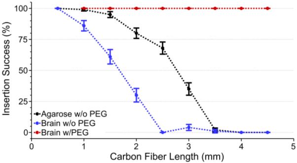
Insertion success rate (mean ± standard error of the mean) of carbon fiber arrays in agarose without PEG (black, n=91 fibers), an explanted rat brain without PEG (blue, n=70 fibers), and an explanted rat brain with PEG coating (red, n=22 fibers). PEG coating enabled a 100% insertion success rate regardless of length or insertion medium, whereas non-PEG coated arrays suffered from a low success rate at lengths longer than 2 mm.
The results from figure 4 were also verified in surgery using non-functional parylene-c coated carbon fiber arrays. As expected, the longest fibers (4 – 5 mm in length) would not insert and any attempt at manipulation with forceps led to many fibers breaking off of the PCB. Attempts to insert the shortest fibers were successful as the very tips were able to penetrate the brain, but they could not go any further as the PCB's back end started to touch the skull's surface before the fibers reached a depth of 500 μm. At these short lengths (500 μm) and with the current PCB design, reaching layer V/VI pyramidal neurons in the rat motor cortex, located 750 – 1750 μm below the cortical surface [70], would be impossible. Also, this target depth does not account for skull thickness [71] and curvature, which necessitates the fibers to be even longer, making it more difficult for them to self-insert.
To reach relevant cortical depths, while taking into account factors such as skull curvature, a coating of 2050 PEG was used to temporarily encapsulate non-functional parylene-c coated fibers of various lengths, while leaving the lower ~500 μm exposed (figure 2(b)). PEG is a safe, biocompatible material, and poses no toxicity to neural tissue [72]. Coating with PEG allowed for a 100% insertion success rate, using three separate arrays with 8, 8, and 6 parylene-c coated fibers one time for each length (n=22 fibers), in a perfused (PBS only) rat brain for fibers of various lengths (figure 4) as long as the exposed length was <1 mm. These results were replicated exactly when using a 0.6% (w/v) agarose phantom (data not shown).
3.1.2. Accelerated Soak Testing of Carbon Fibers
As a new formulation of PEDOT was used, when compared to our previous work [60], an accelerated soak test was carried out to determine if the new formula could maintain a low impedance that would allow for chronic recordings over at least a one month time course. To test this, fibers were first mounted to printed circuit boards, coated with parylene-c, and then had the tips cut off to expose a bare carbon site. The exposed fiber tips were then coated in PEDOT:pTS. Finally, the fully functionalized carbon fibers (n=23 fibers from 3 arrays) were submerged in 1x PBS that was maintained at 60 °C.
Impedance measurements at multiple time points, including just prior to the PEDOT:pTS deposition, were taken to assess the viability of the PEDOT:pTS coating (figure 5). While the impedance at 1 kHz rose from 118 kΩ ± 28 kΩ (mean ± standard error of the mean) at simulated day 0, to 321 kΩ ± 56 kΩ (mean ± standard error of the mean) at simulated day 29.5, these values were found to be acceptable for one month recordings. In addition, subsequent chronic implants also verified the ability of implanted functionalized fibers to record single unit action potentials, one month post implant.
Figure 5.
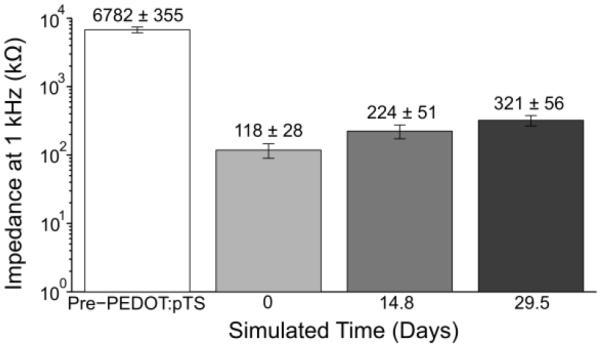
1 kHz impedance values (mean ± standard error of the mean) of functionalized carbon fibers undergoing an accelerated soak test. The pre-PEDOT:pTS impedance value of the fibers with exposed carbon tips (n=23 fibers) was 6782 kΩ ± 355 kΩ. This impedance decreased to 118 kΩ ± 28 kΩ, post-PEDOT:pTS deposition at day 0. From day 0 to simulated day 14.8, impedance increased by roughly 100 kΩ, with a similar increase from simulated day 14.8 to 29.5.
3.2. Surgical Implantation of PEG Coated Carbon Fibers
After verifying the ability of PEG coated carbon fibers to self-insert and of PEDOT:pTS coated fibers to maintain their low impedance at 1 kHz, chronic in vivo surgeries were carried out using carbon fiber arrays with fibers that were approximately 4 – 5 mm in length. During surgery the short exposed ends (~500 μm) of the PEG coated carbon fibers had no difficulty penetrating the brain. Step-by-step drawings and images illustrating the insertion of PEG coated arrays during surgery, along with removal of the PEG can be seen in figure 6. This surgical method was used to chronically implant parylene-c and PEDOT:pTS coated carbon fiber arrays (n=60 fibers from 5 arrays) into five Long Evans rats. Each processing step was confirmed with both EIS and CV measurements (figures 7(a) and-7(c)). EIS measurements are reported for 1 kHz (figure 7(b)), in addition to the calculated CSC (figure 7(d)) from the CV curves. All rats showed single unit activity. A diagram of each probe's implanted and non-implanted fibers are shown in figure 8(a) as blue and red circles, respectively. Representative sorted units and high-speed recordings, from days 1 and 31 post-implant, are shown in figures 8(b) and 8(c), respectively. Full sorted unit and high speed recording panels for every implanted electrode at days 1 and 31 can be seen in figures S1–S4.
Figure 6.

Drawings and surgical images illustrating the insertion process of a PEG coated carbon fiber array. (a) The PEG coated array is lowered until the fibers tips are just above the brain. (b) The array is driven down manually over the course of 5 – 10 seconds and stopped just before the PEG touches the brain's surface. (c) The craniotomy is filled with room temperature sterile Lactated Ringer's using a syringe. Any PEG that comes in to contact with the Ringer's will start to dissolve. As the Ringer's becomes saturated with PEG, a surgical spear is used to absorb the solution and the process is repeated until an additional 500 μm – 1 mm of fiber has been exposed. (d) The carbon fiber array is partially inserted into the brain and more of the fibers have been exposed with the selective removal of PEG from (c). The steps illustrated in (b) – (d) are repeated until the final target depth has been reached which takes approximately 15 – 20 minutes. (e) Surgical image of fibers that have been partially driven in and PEG that has been partially removed, similar to (d). (f) After reaching the target depth, the remaining PEG is exposed to Ringer's and is completely removed. (g) An image from surgery showing all fibers inserted into the brain at their final target depth and removal of all remaining PEG, similar to (f). (h) Accessible ZIF connection of a chronically implanted carbon fiber array. PCB was secured to the skull using dental acrylic.
Figure 7.

(a) Impedance magnitude values (mean ± standard error of the mean) were calculated across a range of frequencies at each functionalization step starting with bare fibers, parylene-c coating, exposing carbon fiber tips post parylene-c deposition, and electrochemical deposition of PEDOT:pTS (n=60 fibers from 5 arrays for each step). Though impedance values for the parylene-c coating step show some perturbations, they likely stem from the excellent insulation properties of this material which makes accurate current flow extremely difficult to measure. Measurements during this step were intended to demonstrate that the coating was present. (b) Impedance magnitude (mean ± standard error of the mean) at 1 kHz for each of the functionalization steps reported in (a). (c) CV plots (mean ± standard error of the mean) for each of the functionalization steps reported in (a). (d) CSC values (mean ± standard error of the mean) for each of the functionalization steps reported in (a).
Figure 8.

(a) Schematic for each animal's implanted probe showing broken sites (red) and sites with a successfully implanted fiber (blue). (b) Average waveforms from a single site for each implant in (a) at days 1 and 31 post-implant. (c) Representative filtered (250 Hz corner, 4th order Butterworth, high-pass) high speed recordings, displaying sorted unit from (b).
The number of successfully implanted carbon fibers (n=60) is less than the theoretical number of 80 (one 16 channel array per animal) due to various factors. The first cause for missing fibers is that the arrays were partially damaged at some point during the fabrication process, starting from the initial placement of fibers to the final PEG coating. Second, during implantation, fibers would sometimes stick to one another and need to be separated using forceps or a surgical spear. During this delicate process an unintended movement could lead to a fiber breaking from the PCB. Third, fibers were purposefully removed if their intended path was obstructed by a major surface blood vessel. Lastly, the fibers were actually implanted but their sites were not coated with PEDOT:pTS or in the particular case of one electrode (ZIF_CF_R19, channel 6), day 1 post-operative impedance values and electrophysiology recordings indicated a broken channel. This last group was classified as broken channels as they exhibited the same impedance and recording qualities of those channels that were actually broken.
3.3. Silicon Support Structure Characterization
3.3.1. Array Design & Assembly
While the application of the PEG coating made insertion of carbon fiber arrays successful, it had some limitations. For carbon fiber arrays with two layers, a PEG coating, which can be difficult to apply at first, is readily achieved in most laboratories due to the minimal equipment needed; however, coating with PEG does not lend itself well to higher density arrays (ie, more than two rows of fibers) using the application method described earlier. To generate higher density arrays a silicon support structure was fabricated that could be stacked with an interposer.
The silicon support structures were fabricated according to the steps outlined in figure 3. Once released from the wafer, the individual devices were mounted on printed circuit boards and a fiber was laid within the groove of each shank. At the end closest to the printed circuit board the fibers were secured using a heat cured silver epoxy (H20E, Epoxy Technology, Billerica, MA). The portion of the fibers that lay in the grooves were secured using an insulating epoxy (301, Epoxy Technology, Billerica, MA) that was also heat cured. The individual silicon shanks had a pitch of 150 μm with a length of either 750 μm or 1000 μm. This fabrication method while not significantly faster compared to the arrays using bare traces, has the important advantages of even carbon fiber spacing, stackability for high density arrays, and a design space that allows for the possibility of even closer shanks. The initial parameters of shank length and pitch were largely informed by the previous results of our PEG coated arrays. The pitch of the shanks was closely matched to that of the carbon arrays from our previous experiments as we already knew that at this close distance the fibers could self-insert. In addition, the two silicon shank lengths were chosen under the assumption that for our fibers to both self-insert and reach layer V/VI of rat motor cortex [70] they would need to extend approximately 500 μm beyond the shank ends.
Initial designs had the eight shanks either terminating in a blunt (figures 9(a) and 9(b)) or pointed end (figures 9(d) and 9(e)), both of which had a maximal width of ~30 μm. Initial experimental surgeries & insertion tests showed the blunt ended shanks causing a large amount of dimpling (figure 9(c)). When 6 blunt silicon shanks of 1000 μm length from one support structure were inserted to a depth of ~650 μm, brain dimpling was measured at 150.5 μm ± 41.4 μm (mean ± standard deviation, n=6). This dimpling was not easily overcome; however, it was partially alleviated by removing every other shank. The tradeoff with this fix was the 50% reduction of carbon fiber density to a 300 μm pitch, which hinders our ability to create a high density device. The pointed shanks however, readily inserted into the brain (figure 9(f)). Performing a similar test as before, 6 pointed silicon shanks of 1000 μm length from one support structure were inserted to a depth of ~650 μm, which resulted in brain dimpling of 33.0 μm ± 11.6 μm (mean ± standard deviation, n=6). This dimpling was significantly less (p < 0.001, one-sided t-test) than that of the blunt shanks and allowed us to maintain the 150 μm pitch needed for our high density arrays.
Figure 9.

(a) & (b) Photo and SEM image of a silicon support structure with 750 μm long blunt shanks and carbon fibers secured within the shanks. (c) & (f) Insertion of blunt shank support structures resulted in a large amount of dimpling at the brain's surface (c) as compared to the pointed shank variant (f). (d) Photo of a silicon support structure with 1000 μm long pointed shanks and carbon fibers secured within the shanks. (e) SEM image of a silicon support structure with a pointed shank.
Another important aspect in designing the support shanks was ensuring that the fibers were as straight as possible, such that particular depths could be reached with reasonable certainty. Carbon fibers within shanks of length, 750 μm and 1000 μm, showed a misalignment of 0.208 ± 0.019° (mean ± standard error of the mean, n=69 fibers from 9 support structure arrays) and 0.157 ± 0.016° (mean ± standard error of the mean, n=71 fibers from 9 support structure arrays) respectively, using the edge of the silicon support structure's backend as a reference. When compared to devices with no shanks (0.311 ± 0.030°, mean ± standard error of the mean, n=76 fibers from 6 arrays), using the edge of the PCB backend as a reference, both shank lengths showed significantly improved alignment (figure 10). All subsequent insertion tests and experimental surgeries were carried out with the pointed silicon shanks.
Figure 10.
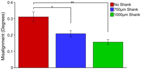
Silicon shank devices show significantly less misalignment (pairwise t-test, Bonferroni correction) than devices fabricated without silicon support structures. * indicates significance at p < 0.01, ** indicates significance at p < 0.001.
3.3.2. Insertion Success
To ensure that the silicon support structures could serve as a viable replacement to our PEG coating, insertion tests with non-functional, parylene-c coated devices were carried out in 0.6% (w/v) agarose and ex vivo using a perfused (PBS only) rat brain. For each test group a single 8 fiber+shank array (750 μm or 1000 μm length silicon shanks with 150 μm shank spacing) was inserted 5 times for each length of protruding fiber (n=40 fibers+shanks per test). As expected, fibers extending 1 mm or less beyond the silicon support shanks inserted into the agarose with nearly 100% success (figure 11) regardless of shank length. The insertion tests into the brain sample (figure 11) were not as successful as the agarose tests, however these metrics do line up well with the previous results seen in figure 4, where the overall insertion success was lower across all lengths except for that of 500 μm. This again demonstrates that 500 μm of exposed fiber is the critical length needed for fiber self-insertion.
Figure 11.
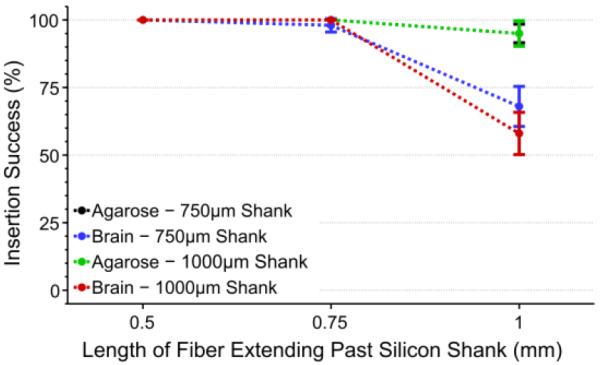
Insertion success rate (mean ± standard error of the mean) of silicon shanks with various length carbon fibers. Both 750 μm (black, n=40 fibers+shanks) and 1000 μm (green, n=40 fibers+shanks) shank lengths showed high insertion percentages in agarose regardless of fiber length. Tests in an explanted brain showed similar success for 750 μm (blue, n=40 fibers+shanks) and 1000 μm (red, n=40 fibers+shanks) shank lengths when fibers were ≤750 μm. All results, regardless of shank length or insertion medium, showed 100% success when fibers were 500 μm in length.
3.3.3. Functionalization & Acute In Vivo Testing
Given the high insertion success rate of the 1000 μm long silicon shanks (150 μm shank spacing) plus 500 μm of exposed carbon fibers, functional tests were carried out to validate this design's ability to record neuronal signals. As this first iteration of devices provided no electrical isolation the entire silicon structure was first coated with an insulating layer of parylene-c once released from the wafer. Silicon structures were then secured to PCBs, and fibers laid within the individual shanks, secured by silver and insulating epoxy (301, Epoxy Technology, Billerica, MA). The entire assembled device was then coated with parylene-c (t=800 nm) to form an insulating layer around the fibers themselves and finally the tips of the fibers were functionalized with PEDOT:pTS. An electrical connection between the silver epoxy contact point of the carbon fibers and the PCBs exposed traces was made using pieces of small copper wire. Due to the inherent difficulties of placing a wire down for each carbon fiber, only every other shank received a carbon fiber (figure 12(a)). Each processing step was confirmed using both EIS and CV measurements (data not shown) that corresponded well to results shown in figure 6(a).
Figure 12.

(a) Image of silicon support structure with carbon fibers. Copper wire (yellow arrow) connects each fiber to traces that leads to the backend headstage. (b) Representative waveforms detected on each site across the multiple implants. (c) Representative 100 ms snippet of filtered (250 Hz corner, 4th order Butterworth, high-pass) high speed recordings from each site.
To demonstrate feasibility of this new device, acute surgery on two Long Evans rats was performed under ketamine/xylazine anesthesia wherein the probes were implanted in the M1 region at a depth of ~1.5 mm. In the first animal (ZIF_CF_Si_R5) a single probe, with four functionalized carbon fibers, was implanted in the left M1 region. In the second animal (ZIF_CF_Si_R11) two different probes, each with three functionalized carbon fibers, were implanted, one in each hemisphere with M1 as the target region. A total of sixteen distinct units were detected across nine of the ten functionalized channels using manual sorting (figures 12(b) and 12(c)). The average amplitude for all sixteen units was 245.9 ± 122.2 μV (mean ± standard deviation). These results demonstrate the in vivo capability of our new silicon support structures to record high quality, single unit action potentials in a repeatable manner.
3.3.4. 3D Support Structure – Functionalization & Acute In Vivo Testing
To fully validate the ability to insert our 3D design of the silicon supports, a stacked non-functional device was fabricated. Three silicon supports with 750 μm long shanks (150 μm shank spacing) and 500 μm of carbon fiber extending past the shanks were stacked with an interposer layer of glass (t=100 μm) (figure 13a). This device was successfully implanted 4 times during an acute surgery on a Long Evans rat (Supplementary video 1).
Figure 13.

(a) Three stacked layers of silicon supports with carbon fibers forming a 3D device. (b) Average waveforms detected on multiple sites at various depths from a fully functionalized 3D device.
Finally, a fully functionalized device (not shown), similar to that in figure 12(a) was fabricated. In total there were three silicon layers with a glass interposer (t=100 μm) between layers. For each silicon support, every other 1000 μm shank (150 μm shank spacing) received a carbon fiber. Due to the limitations of the PCB, only four of the twelve available recordings sites were electrically connected. During an acute procedure on one Long Evans rat under ketamine/xylazine anesthesia, recordings were taken with the functionalized device at multiple recordings depths in the M1 region. Single unit and multiunit action potentials were detected on multiple channels at various depths (figure 13(b)).
4. Discussion
4.1. Ex Vivo Characterization & Accelerated Soak Tests
In this work we first sought to characterize the potential ability of carbon fiber arrays to self-penetrate the brain and record chronic unit activity. Insertion dynamics and recording site stability were evaluated using ex vivo and accelerated soak tests, respectively. The ex vivo tests were carried out on PBS only perfused rat brains and showed that 500 μm long carbon fibers self-inserted with a 100% success rate. Accelerated soak tests demonstrated an increasing site impedance when aged to a simulated time of ~30 days, but remained low enough for the detection of single units.
While these tests were not designed to be exact substitutes for chronic in vivo implantation of the carbon fibers, they did serve as methods for rapid, high throughput characterization. Additionally, our later in vivo studies confirmed the findings of these benchtop results.
4.2. PEG
Following the initial carbon fiber characterization using accelerated soak tests and PBS perfused rat brains, we established the ability to chronically implant individual arrays of 8.4 μm carbon fiber electrodes, with an electrode pitch of ~150 μm. Self-insertion was achieved by taking advantage of the carbon fibers' high Young's modulus, which allowed them to penetrate the brain at exposed lengths of 500 μm. This unique property, along with a temporary PEG coating allowed us to reach cortical depths of ~1.5 mm without causing substantial insertion injury as evidenced by the detection of single unit action potentials in chronic implants. This penetration depth is sufficient for reaching hippocampus CA1 stratum pyramidale layers in mice, cortical layer VI in rats, and cortical layer V in primates. With this preparation we have avoided the use of an insertion shuttle which can increase the insertion injury to the tissue immediately surrounding the electrode. To the best of our knowledge these carbon fiber arrays set a new record for electrode shank pitch when compared to the most commonly used chronically implanted functional MEAs (Table 1). These higher density arrays can facilitate the study of horizontal cortical communications, such as lateral inhibition and adaptation, in neuroscience studies and BMI applications.
Table 1.
Commercially available MEAs commonly used in research labs.
| MEA Technology | Shank Pitch | Electrode Shank Size | Recording Site Diameter | Shank Length | Materials |
|---|---|---|---|---|---|
| Carbon Fibers | 150 – 152.4 μm | 8.4 μm diameter with insulation coating | 6.8 μm | 0.5 – 5 mm | Carbon Fiber + PEDOT:pTS |
| Blackrock Microsystems (Utah Array) [12,14,73,74] | 400 μm | 90 μm × 90 μm at base, 5 μm tip diameter | 40 μm tapering to 5 μm | 1 – 1.5 mm | Silicon + Platinum |
| Microprobes [75] | 400 μm | 75 μm diameter | 2 – 3 μm | 1.5 mm | Platinum/Iridium |
| Tucker-Davis Technologies [76] | 250 μm | 50 μm diameter | 50 μm | 5 mm | Tungsten |
| NeuroNexus, Inc. [77] | 400 μm | 50 μm thickness × variable width | 15 μm | 1.4 mm (implant depth) | Silicon + Iridium |
The findings from the PEG study suggest that ultra-fine electrodes made from other materials may also have the right properties to self-insert and avoid the use of an insertion shuttle. While the PEG coating method has shown the ability to chronically implant up to 16 fibers, it is still limited to only two rows of fibers. Increasing the number of rows to three or more would greatly complicate the existing coating method. To address this challenge, we looked to build upon our knowledge of carbon fiber insertion dynamics and design a platform that could support multiple rows of fibers, while also maintaining a comparable pitch.
4.3. Silicon Support Structure
Therefore, a stackable silicon support structure was fabricated which could improve the capabilities and channel count of future carbon fiber arrays. The blunt ended silicon structures we originally developed were expected to readily penetrate the brain, given their small footprint of ~30 μm (w) × ~24 μm (h). However, upon testing it was determined that a pitch of 150 μm led to a large amount of dimpling. The same style device with a tapered end, caused significantly less dimpling at the original 150 μm pitch. This highlights the clear tradeoff between a device's shape, no matter how small, and its pitch. This device was then tested with a single layer of carbon fibers and showed similar insertion success rate vs. length dynamics as the PEG coated arrays. Further tests using fully functionalized devices demonstrated the ability to record action potentials in an acute setting. Lastly, a 3D device consisting of multiple stacked silicon supports was constructed and was also shown to work in vivo. This new silicon platform will allow for a modular and highly customizable approach to building 3D arrays. Depending upon the application, shank pitch, length, and count can be varied within and between individual stacked layers.
4.4. Future Directions
While more work is needed to fully understand the long-term viability of these new arrays, the first step is to characterize the insertion mechanics and assembly methods as these variables may impact longitudinal performance. An improved PCB design with a ground plane between both, layers and traces, is being actively explored to alleviate any potential cross-talk between channels. Currently our group is working on quantifying the long term recording stability of chronically implanted carbon fiber arrays and studying the immune response of such small carbon fiber electrodes through histological analysis of multi month animal implants. Histological studies could help to determine the path and any possible deviation of the fiber arrays, which may be subject to micromotion over the duration of the implant.
Additionally, while the goal of this study was not to test insulation or site coatings, but to develop and evaluate insertion tools for scalable, high-density carbon fiber arrays, more work needs to be done exploring how chronic implantation may affect the performance and adherence of the PEDOT:pTS and parylene-c coatings. The longevity of both have been explored by a few groups, some using soak test methods [61,62,78] and others using data from chronic implants [14,79], but no definitive conclusions have been reached. This is partially attributable to the different conditions under which each material is used. If current methods are found to be non-ideal there are a variety of other insulating [80,81] and conductive [82–85] coating methods available (see [86] for review). Lastly, integration of nanoscale covalent surface chemistries, such as PEG based anti-biofouling coatings [60], neural adhesion molecule coatings [87], and drug eluting coatings [88], are further expected to improve longitudinal recording performance as well as neuromodulation or wireless neural stimulation applications **.
4.5. Conclusion
With the ability for each site to record from a ~75 μm radius [89], this array theoretically has the potential to record from all active neurons in a given cortical layer. Longer term, methods need to be developed that will allow for the scaling up of manufacturing throughput and even higher densities of carbon fibers. Assembly with silver epoxy could be eliminated using a self-aligning anisotropic epoxy that self-selectively forms electrical connections between fibers and traces [90]. Innovative methods will be needed for the frontend silicon support structure but also in the backend where dozens if not hundreds of wires [14] will be needed to transmit electrophysiological data. Packaging arrays with an ASIC capable of multiplexing hundreds of channels [91] would alleviate many wiring issues [2,92] or completely eliminate them [93–95]. The convergence of these technologies could lead to an electrode pitch dense enough to record from all neurons in a given space for long periods of time.
Supplementary Material
Acknowledgements
The authors would like to thank Dr. Joshua Berke and Jeffrey Pettibone for helpful discussions regarding the targeting of subcortical structures. The authors would also like to thank Karen Schroeder for discussions related to the PEG coating process and Matthew Robbins who assisted with some of the animal recording sessions. Thanks to the University of Michigan's Electron Microbeam Analysis Laboratory and the Lurie Nanofabrication Facility for use of their equipment.
This work was financially supported by the Department of Energy (DE-SC0000957), the National Science Foundation (DMR-0320740), and the National Institute of Neurological Disorders and Stroke (1RC1NS068396-0110).
References
- [1].Nicolelis MAL, Dimitrov D, Carmena JM, Crist R, Lehew G, Kralik JD, Wise SP. Chronic, multisite, multielectrode recordings in macaque monkeys. Proc. Natl. Acad. Sci. 2003;100:11041–6. doi: 10.1073/pnas.1934665100. [DOI] [PMC free article] [PubMed] [Google Scholar]
- [2].Berényi A, Somogyvári Z, Nagy AJ, Roux L, Long JD, Fujisawa S, Stark E, Leonardo A, Harris TD, Buzsáki G. Large-scale, high-density (up to 512 channels) recording of local circuits in behaving animals. J. Neurophysiol. 2014;111:1132–49. doi: 10.1152/jn.00785.2013. [DOI] [PMC free article] [PubMed] [Google Scholar]
- [3].Carmena JM, Lebedev MA, Crist RE, O'Doherty JE, Santucci DM, Dimitrov DF, Patil PG, Henriquez CS, Nicolelis MAL. Learning to control a brain-machine interface for reaching and grasping by primates. PLoS Biol. 2003;1:193–208. doi: 10.1371/journal.pbio.0000042. [DOI] [PMC free article] [PubMed] [Google Scholar]
- [4].Simeral JD, Kim S-P, Black MJ, Donoghue JP, Hochberg LR. Neural control of cursor trajectory and click by a human with tetraplegia 1000 days after implant of an intracortical microelectrode array. J. Neural Eng. 2011;8:25027. doi: 10.1088/1741-2560/8/2/025027. [DOI] [PMC free article] [PubMed] [Google Scholar]
- [5].Hochberg LR, Serruya MD, Friehs GM, Mukand JA, Saleh M, Caplan AH, Branner A, Chen D, Penn RD, Donoghue JP. Neuronal ensemble control of prosthetic devices by a human with tetraplegia. Nature. 2006;442:164–71. doi: 10.1038/nature04970. [DOI] [PubMed] [Google Scholar]
- [6].Schwartz AB. Cortical Neural Prosthetics. Annu. Rev. Neurosci. 2004;27:487–507. doi: 10.1146/annurev.neuro.27.070203.144233. [DOI] [PubMed] [Google Scholar]
- [7].Williams JC, Rennaker RL, Kipke DR. Long-term neural recording characteristics of wire microelectrode arrays implanted in cerebral cortex. Brain Res. Protoc. 1999;4:303–13. doi: 10.1016/s1385-299x(99)00034-3. [DOI] [PubMed] [Google Scholar]
- [8].Rennaker RL, Ruyle AM, Street SE, Sloan AM. An economical multi-channel cortical electrode array for extended periods of recording during behavior. J. Neurosci. Methods. 2005;142:97–105. doi: 10.1016/j.jneumeth.2004.07.018. [DOI] [PubMed] [Google Scholar]
- [9].Vetter RJ, Williams JC, Hetke JF, Nunamaker EA, Kipke DR. Chronic neural recording using silicon-substrate microelectrode arrays implanted in cerebral cortex. IEEE Trans. Biomed. Eng. 2004;51:896–904. doi: 10.1109/TBME.2004.826680. [DOI] [PubMed] [Google Scholar]
- [10].Kipke DR, Vetter RJ, Williams JC, Hetke JF. Silicon-substrate intracortical microelectrode arrays for long-term recording of neuronal spike activity in cerebral cortex. IEEE Trans. Neural Syst. Rehabil. Eng. 2003;11:151–5. doi: 10.1109/TNSRE.2003.814443. [DOI] [PubMed] [Google Scholar]
- [11].Kozai TDY, Du Z, Gugel ZV, Smith MA, Chase SM, Bodily LM, Caparosa EM, Friedlander RM, Cui XT. Comprehensive chronic laminar single-unit, multi-unit, and local field potential recording performance with planar single shank electrode arrays. J. Neurosci. Methods. 2015;242:15–40. doi: 10.1016/j.jneumeth.2014.12.010. [DOI] [PMC free article] [PubMed] [Google Scholar]
- [12].Nordhausen CT, Maynard EM, Normann RA. Single unit recording capabilities of a 100 microelectrode array. Brain Res. 1996;726:129–40. [PubMed] [Google Scholar]
- [13].Wark HAC, Sharma R, Mathews KS, Fernandez E, Yoo J, Christensen B, Tresco P, Rieth L, Solzbacher F, Normann RA, Tathireddy P. A new high-density (25 electrodes/mm 2) penetrating microelectrode array for recording and stimulating submillimeter neuroanatomical structures. J. Neural Eng. 2013;10:45003. doi: 10.1088/1741-2560/10/4/045003. [DOI] [PubMed] [Google Scholar]
- [14].Barrese JC, Rao N, Paroo K, Triebwasser C, Vargas-Irwin C, Franquemont L, Donoghue JP. Failure mode analysis of silicon-based intracortical microelectrode arrays in non-human primates. J. Neural Eng. 2013;10:66014. doi: 10.1088/1741-2560/10/6/066014. [DOI] [PMC free article] [PubMed] [Google Scholar]
- [15].Johnson MD, Kao OE, Kipke DR. Spatiotemporal pH dynamics following insertion of neural microelectrode arrays. J. Neurosci. Methods. 2007;160:276–87. doi: 10.1016/j.jneumeth.2006.09.023. [DOI] [PubMed] [Google Scholar]
- [16].Bjornsson CS, Lin G, Al-Kofahi Y, Narayanaswamy A, Smith KL, Shain W, Roysam B. Associative image analysis: a method for automated quantification of 3D multi-parameter images of brain tissue. J. Neurosci. Methods. 2008;170:165–78. doi: 10.1016/j.jneumeth.2007.12.024. [DOI] [PMC free article] [PubMed] [Google Scholar]
- [17].Kozai TDY, Marzullo TC, Hooi F, Langhals NB, Majewska AK, Brown EB, Kipke DR. Reduction of neurovascular damage resulting from microelectrode insertion into the cerebral cortex using in vivo two-photon mapping. J. Neural Eng. 2010;7:46011. doi: 10.1088/1741-2560/7/4/046011. [DOI] [PMC free article] [PubMed] [Google Scholar]
- [18].Biran R, Martin DC, Tresco PA. Neuronal cell loss accompanies the brain tissue response to chronically implanted silicon microelectrode arrays. Exp. Neurol. 2005;195:115–26. doi: 10.1016/j.expneurol.2005.04.020. [DOI] [PubMed] [Google Scholar]
- [19].Potter KA, Buck AC, Self WK, Capadona JR. Stab injury and device implantation within the brain results in inversely multiphasic neuroinflammatory and neurodegenerative responses. J. Neural Eng. 2012;9:46020. doi: 10.1088/1741-2560/9/4/046020. [DOI] [PubMed] [Google Scholar]
- [20].Kozai TDY, Gugel Z, Li X, Gilgunn PJ, Khilwani R, Ozdoganlar OB, Fedder GK, Weber DJ, Cui XT. Chronic tissue response to carboxymethyl cellulose based dissolvable insertion neneed for ultra-small neural probes. Biomaterials. 2014;35:9620–34. doi: 10.1016/j.biomaterials.2014.07.039. [DOI] [PubMed] [Google Scholar]
- [21].Edell DJ, Toi VV, McNeil VM, Clark LD. Factors influencing the biocompatibility of insertable silicon microshafts in cerebral cortex. IEEE Trans. Biomed. Eng. 1992;39:635–43. doi: 10.1109/10.141202. [DOI] [PubMed] [Google Scholar]
- [22].Carter RR, Houk JC. Multiple single-unit recordings from the CNS using thin-film electrode arrays. IEEE Trans. Rehabil. Eng. 1993;1:175–84. [Google Scholar]
- [23].Schmidt S, Horch K, Normann R. Biocompatibility of Silicon-based Electrode Arrays Implanted In Feline Cortical Tissue. J. Biomed. Mater. Res. 1993;27:1393–9. doi: 10.1002/jbm.820271106. [DOI] [PubMed] [Google Scholar]
- [24].Turner JN, Shain W, Szarowski DH, Andersen M, Martins S, Isaacson M, Craighead H. Cerebral Astrocyte Response to Micromachined Silicon Implants. Exp. Neurol. 1999;156:33–49. doi: 10.1006/exnr.1998.6983. [DOI] [PubMed] [Google Scholar]
- [25].Liu X, McCreery DB, Carter RR, Bullara LA, Yuen TGH, Agnew WF. Stability of the interface between neural tissue and chronically implanted intracortical microelectrodes. IEEE Trans. Rehabil. Eng. 1999;7:315–26. doi: 10.1109/86.788468. [DOI] [PubMed] [Google Scholar]
- [26].Szarowski DH, Andersen MD, Retterer S, Spence AJ, Isaacson M, Craighead HG, Turner JN, Shain W. Brain responses to micro-machined silicon devices. Brain Res. 2003;983:23–35. doi: 10.1016/s0006-8993(03)03023-3. [DOI] [PubMed] [Google Scholar]
- [27].Polikov VS, Tresco PA, Reichert WM. Response of brain tissue to chronically implanted neural electrodes. J. Neurosci. Methods. 2005;148:1–18. doi: 10.1016/j.jneumeth.2005.08.015. [DOI] [PubMed] [Google Scholar]
- [28].McConnell GC, Rees HD, Levey AI, Gutekunst C-A, Gross RE, Bellamkonda RV. Implanted neural electrodes cause chronic, local inflammation that is correlated with local neurodegeneration. J. Neural Eng. 2009;6:56003. doi: 10.1088/1741-2560/6/5/056003. [DOI] [PubMed] [Google Scholar]
- [29].Grand L, Wittner L, Herwik S, Göthelid E, Ruther P, Oscarsson S, Neves H, Dombovári B, Csercsa R, Karmos G, Ulbert I. Short and long term biocompatibility of NeuroProbes silicon probes. J. Neurosci. Methods. 2010;189:216–29. doi: 10.1016/j.jneumeth.2010.04.009. [DOI] [PubMed] [Google Scholar]
- [30].Winslow BD, Tresco PA. Quantitative analysis of the tissue response to chronically implanted microwire electrodes in rat cortex. Biomaterials. 2010;31:1558–67. doi: 10.1016/j.biomaterials.2009.11.049. [DOI] [PubMed] [Google Scholar]
- [31].Kozai TDY, Vazquez AL, Weaver CL, Kim S-G, Cui XT. In vivo two-photon microscopy reveals immediate microglial reaction to implantation of microelectrode through extension of processes. J. Neural Eng. 2012;9:66001. doi: 10.1088/1741-2560/9/6/066001. [DOI] [PMC free article] [PubMed] [Google Scholar]
- [32].Muthuswamy J, Gilletti A, Jain T, Okandan M. Microactuated neural probes to compensate for brain micromotion. 2003 Annu. Int. Conf. IEEE Eng. Med. Biol. Soc. 2003;2:1941–3. [Google Scholar]
- [33].Karumbaiah L, Saxena T, Carlson D, Patil K, Patkar R, Gaupp EA, Betancur M, Stanley GB, Carin L, Bellamkonda RV. Relationship between intracortical electrode design and chronic recording function. Biomaterials. 2013;34:8061–74. doi: 10.1016/j.biomaterials.2013.07.016. [DOI] [PubMed] [Google Scholar]
- [34].Saxena T, Karumbaiah L, Gaupp EA, Patkar R, Patil K, Betancur M, Stanley GB, Bellamkonda RV. The impact of chronic blood-brain barrier breach on intracortical electrode function. Biomater. 2013;34:4703–13. doi: 10.1016/j.biomaterials.2013.03.007. [DOI] [PubMed] [Google Scholar]
- [35].Kozai TDY, Li X, Bodily LM, Caparosa EM, Zenonos GA, Carlisle DL, Friedlander RM, Cui XT. Effects of caspase-1 knockout on chronic neural recording quality and longevity: Insight into cellular and molecular mechanisms of the reactive tissue response. Biomaterials. 2014;35:9255–68. doi: 10.1016/j.biomaterials.2014.08.006. [DOI] [PMC free article] [PubMed] [Google Scholar]
- [36].Kozai TDY, Jaquins-Gerstl AS, Vazquez AL, Michael AC, Cui XT. Brain Tissue Responses to Neural Implants Impact Signal Sensitivity and Intervention Strategies. ACS Chem. Neurosci. 2015;6:48–67. doi: 10.1021/cn500256e. [DOI] [PMC free article] [PubMed] [Google Scholar]
- [37].Harris JP, Capadona JR, Miller RH, Healy BC, Shanmuganathan K, Rowan SJ, Weder C, Tyler DJ. Mechanically adaptive intracortical implants improve the proximity of neuronal cell bodies. J. Neural Eng. 2011;8:66011. doi: 10.1088/1741-2560/8/6/066011. [DOI] [PMC free article] [PubMed] [Google Scholar]
- [38].Harris JP, Hess AE, Rowan SJ, Weder C, Zorman CA, Tyler DJ, Capadona JR. In vivo deployment of mechanically adaptive nanocomposites for intracortical microelectrodes. J. Neural Eng. 2011;8:46010. doi: 10.1088/1741-2560/8/4/046010. [DOI] [PMC free article] [PubMed] [Google Scholar]
- [39].Ware T, Simon D, Hearon K, Liu C, Shah S, Reeder J, Khodaparast N, Kilgard MP, Maitland DJ, Rennaker RL, Voit WE. Three-Dimensional Flexible Electronics Enabled by Shape Memory Polymer Substrates for Responsive Neural Interfaces. Macromol. Mater. Eng. 2012;297:1193–202. doi: 10.1002/mame.201200241. [DOI] [PMC free article] [PubMed] [Google Scholar]
- [40].Kim BJ, Kuo JTW, Hara SA, Lee CD, Yu L, Gutierrez CA, Hoang TQ, Pikov V, Meng E. 3D Parylene sheath neural probe for chronic recordings. J. Neural Eng. 2013;10:45002. doi: 10.1088/1741-2560/10/4/045002. [DOI] [PubMed] [Google Scholar]
- [41].Takeuchi S, Ziegler D, Yoshida Y, Mabuchi K, Suzuki T. Parylene flexible neural probes integrated with microfluidic channels. Lab. 2005;5:519–23. doi: 10.1039/b417497f. [DOI] [PubMed] [Google Scholar]
- [42].Rousche PJ, Pellinen DS, Pivin DP, Williams JC, Vetter RJ, Kipke DR. Flexible polyimide-based intracortical electrode arrays with bioactive capability. IEEE Trans. Biomed. Eng. 2001;48:361–71. doi: 10.1109/10.914800. [DOI] [PubMed] [Google Scholar]
- [43].McClain M, Clements I, Shafer R, Bellamkonda R, LaPlaca M, Allen M. Highly-compliant, microcable neuroelectrodes fabricated from thin-film gold and PDMS. Biomed. Microdevices. 2011;13:361–73. doi: 10.1007/s10544-010-9505-3. [DOI] [PubMed] [Google Scholar]
- [44].Kozai TDY, Kipke DR. Insertion shuttle with carboxyl terminated self-assembled monolayer coatings for implanting flexible polymer neural probes in the brain. J. Neurosci. Methods. 2009;184:199–205. doi: 10.1016/j.jneumeth.2009.08.002. [DOI] [PMC free article] [PubMed] [Google Scholar]
- [45].Ware T, Simon D, Liu C, Musa T, Vasudevan S, Sloan A, Keefer EW, Rennaker RL, Voit W. Thiol-ene/acrylate substrates for softening intracortical electrodes. J. Biomed. Mater. Res. Part B Appl. Biomater. 2014;102:1–11. doi: 10.1002/jbmb.32946. [DOI] [PubMed] [Google Scholar]
- [46].Kozai TDY, Catt K, Li X, Gugel ZV, Olafsson VT, Vazquez AL, Cui XT. Mechanical failure modes of chronically implanted planar silicon-based neural probes for laminar recording. Biomaterials. 2015;37:25–39. doi: 10.1016/j.biomaterials.2014.10.040. [DOI] [PMC free article] [PubMed] [Google Scholar]
- [47].Skousen JL, Merriam SME, Srivannavit O, Perlin G, Wise KD, Tresco PA. Reducing surface area while maintaining implant penetrating profile lowers the brain foreign body response to chronically implanted planar silicon microelectrode arrays. Prog. Brain Res. 2011;194:167–80. doi: 10.1016/B978-0-444-53815-4.00009-1. [DOI] [PubMed] [Google Scholar]
- [48].Gilgunn PJ, Khilwani R, Kozai TDY, Weber DJ, Cui XT, Erdos G, Ozdoganlar OB, Fedder GK. 2012 IEEE 25th Int. Conf. Micro Electro Mech. Syst. 2012. An ultra-compliant, scalable neural probe with molded biodissolvable delivery vehicle; pp. 56–9. [Google Scholar]
- [49].Seymour JP, Kipke DR. Neural probe design for reduced tissue encapsulation in CNS. Biomaterials. 2007;28:3594–607. doi: 10.1016/j.biomaterials.2007.03.024. [DOI] [PubMed] [Google Scholar]
- [50].MatWeb . Cytec Thornel® T-650/35 3K Carbon Fiber, Polyacrylonitrile (PAN) Precursor. 2012. [Google Scholar]
- [51].Dolbow J, Gosz M. Effect of out-of-plane properties of a polyimide film on the stress fields in microelectronic structures. Mech. Mater. 1996;23:311–21. [Google Scholar]
- [52].Armstrong-James M, Millar J. Carbon fibre microelectrodes. J. Neurosci. Methods. 1979;1:279–87. doi: 10.1016/0165-0270(79)90039-6. [DOI] [PubMed] [Google Scholar]
- [53].Budai D. In: Carbon Fiber-based Microelectrodes and Microbiosensors, Intelligent and Biosensors. Somerset VS, editor. 2010. InTech. [Google Scholar]
- [54].Ponchon JL, Cespuglio R, Gonon F, Jouvet M, Pujol JF. Normal Pulse Polarography With Carbon-fiber Electrodes For Invitro and Invivo Determination of Catecholamines. Anal. Chem. 1979;51:1483–6. doi: 10.1021/ac50045a030. [DOI] [PubMed] [Google Scholar]
- [55].Rebec GV, Christensen JRC, Guerra C, Bardo MT. Regional and temporal differences in real-time dopamine efflux in the nucleus accumbens during free-choice novelty. Brain Res. 1997;776:61–7. doi: 10.1016/s0006-8993(97)01004-4. [DOI] [PubMed] [Google Scholar]
- [56].Park J, Takmakov P, Wightman RM. In vivo comparison of norepinephrine and dopamine release in rat brain by simultaneous measurements with fast-scan cyclic voltammetry. J. Neurochem. 2011;119:932–44. doi: 10.1111/j.1471-4159.2011.07494.x. [DOI] [PMC free article] [PubMed] [Google Scholar]
- [57].Heien MLAV, Johnson MA, Wightman RM. Resolving neurotransmitters detected by fast-scan cyclic voltammetry. Anal. Chem. 2004;76:5697–704. doi: 10.1021/ac0491509. [DOI] [PubMed] [Google Scholar]
- [58].Ferris MJ, Calipari ES, Yorgason JT, Jones SR. Examining the Complex Regulation and Drug-Induced Plasticity of Dopamine Release and Uptake Using Voltammetry in Brain Slices. ACS Chem. Neurosci. 2013;4:693–703. doi: 10.1021/cn400026v. [DOI] [PMC free article] [PubMed] [Google Scholar]
- [59].Guitchounts G, Markowitz JE, Liberti WA, Gardner TJ. A carbon-fiber electrode array for long-term neural recording. J. Neural Eng. 2013;10:46016. doi: 10.1088/1741-2560/10/4/046016. [DOI] [PMC free article] [PubMed] [Google Scholar]
- [60].Kozai TDY, Langhals NB, Patel PR, Deng X, Zhang H, Smith KL, Lahann J, Kotov NA, Kipke DR. Ultrasmall implantable composite microelectrodes with bioactive surfaces for chronic neural interfaces. Nat. Mater. 2012;11:1065–73. doi: 10.1038/nmat3468. [DOI] [PMC free article] [PubMed] [Google Scholar]
- [61].Hsu J-M, Rieth L, Normann RA, Tathireddy P, Solzbacher F. Encapsulation of an Integrated Neural Interface Device With Parylene C. IEEE Trans. Biomed. Eng. 2009;56:23–9. doi: 10.1109/TBME.2008.2002155. [DOI] [PubMed] [Google Scholar]
- [62].Green RA, Hassarati RT, Bouchinet L, Lee CS, Cheong GLM, Yu JF, Dodds CW, Suaning GJ, Poole-Warren LA, Lovell NH. Substrate dependent stability of conducting polymer coatings on medical electrodes. Biomaterials. 2012;33:5875–86. doi: 10.1016/j.biomaterials.2012.05.017. [DOI] [PubMed] [Google Scholar]
- [63].Hukins DWL, Mahomed A, Kukureka SN. Accelerated aging for testing polymeric biomaterials and medical devices. Med. Eng. Phys. 2008;30:1270–4. doi: 10.1016/j.medengphy.2008.06.001. [DOI] [PubMed] [Google Scholar]
- [64].ATSM F-07 . Standard Guide for Accelerated Aging of Sterile Barrier Systems for Medical Devices. 2011. [Google Scholar]
- [65].Paxinos G, Watson C. The Rat Brain in Stereotaxic Coordinates. Academic Press; 2007. [DOI] [PubMed] [Google Scholar]
- [66].Nunamaker EA, Kipke DR. An alginate hydrogel dura mater replacement for use with intracortical electrodes. J. Biomed. Mater. Res. Part B Appl. Biomater. 2010;95B:421–9. doi: 10.1002/jbm.b.31733. [DOI] [PubMed] [Google Scholar]
- [67].Bai Q, Wise KD, Anderson DJ. A high-yield microassembly structure for three-dimensional microelectrode arrays. IEEE Trans. Biomed. Eng. 2000;47:281–9. doi: 10.1109/10.827288. [DOI] [PubMed] [Google Scholar]
- [68].Wise KD, Anderson DJ, Hetke JF, Kipke DR, Najafi K. Wireless implantable microsystems: High-density electronic interfaces to the nervous system. Proc. IEEE. 2004;92:76–97. [Google Scholar]
- [69].Chen ZJ, Gillies GT, Broaddus WC, Prabhu SS, Fillmore H, Mitchell RM, Corwin FD, Fatouros PP. A realistic brain tissue phantom for intraparenchymal infusion studies. J. Neurosurg. 2004;101:314–22. doi: 10.3171/jns.2004.101.2.0314. [DOI] [PubMed] [Google Scholar]
- [70].Skoglund TS, Pascher R, Berthold CH. The existence of a layer IV in the rat motor cortex. Cereb. Cortex. 1997;7:178–80. doi: 10.1093/cercor/7.2.178. [DOI] [PubMed] [Google Scholar]
- [71].Li PC, Ni SL, Zhang L, Zeng SQ, Luo QM. Imaging cerebral blood flow through the intact rat skull with temporal laser speckle imaging. Opt. Lett. 2006;31:1824–6. doi: 10.1364/ol.31.001824. [DOI] [PubMed] [Google Scholar]
- [72].Mahoney MJ, Anseth KS. Three-dimensional growth and function of neural tissue in degradable polyethylene glycol hydrogels. Biomater. 2006;27:2265–74. doi: 10.1016/j.biomaterials.2005.11.007. [DOI] [PubMed] [Google Scholar]
- [73].Normann RA, Maynard EM, Rousche PJ, Warren DJ. A neural interface for a cortical vision prosthesis. Vis. Res. 1999;39:2577–87. doi: 10.1016/s0042-6989(99)00040-1. [DOI] [PubMed] [Google Scholar]
- [74].Negi S, Bhandari R, Rieth L, Solzbacher F. In vitro comparison of sputtered iridium oxide and platinum-coated neural implantable microelectrode arrays. Biomed. Mater. 2010;5:15007. doi: 10.1088/1748-6041/5/1/015007. [DOI] [PubMed] [Google Scholar]
- [75].Prasad A, Xue Q-S, Dieme R, Sankar V, Mayrand RC, Nishida T, Streit WJ, Sanchez JC. Abiotic-biotic characterization of Pt/Ir microelectrode arrays in chronic implants. Front. Neuroeng. 2014;7:1–15. doi: 10.3389/fneng.2014.00002. [DOI] [PMC free article] [PubMed] [Google Scholar]
- [76].Sankar V, Patrick E, Dieme R, Sanchez JC, Prasad A, Nishida T. Electrode impedance analysis of chronic tungsten microwire neural implants: understanding abiotic vs. biotic contributions. Front. Neuroeng. 2014;7:1–12. doi: 10.3389/fneng.2014.00013. [DOI] [PMC free article] [PubMed] [Google Scholar]
- [77].Riera JJ, Ogawa T, Goto T, Sumiyoshi A, Nonaka H, Evans A, Miyakawa H, Kawashima R. Pitfalls in the dipolar model for the neocortical EEG sources. J. Neurophysiol. 2012;108:956–75. doi: 10.1152/jn.00098.2011. [DOI] [PubMed] [Google Scholar]
- [78].Li W, Rodger DC, Meng E, Weiland JD, Humayun MS, Tai Y-C. Wafer-Level Parylene Packaging With Integrated RF Electronics for Wireless Retinal Prostheses. J. Microelectromechanical Syst. 2010;19:735–42. [Google Scholar]
- [79].Ludwig KA, Uram JD, Yang J, Martin DC, Kipke DR. Chronic neural recordings using silicon microelectrode arrays electrochemically deposited with a poly(3,4-ethylenedioxythiophene) (PEDOT) film. J. Neural Eng. 2006;3:59–70. doi: 10.1088/1741-2560/3/1/007. [DOI] [PubMed] [Google Scholar]
- [80].Katira P, Agarwal A, Fischer T, Chen H-Y, Jiang X, Lahann J, Hess H. Quantifying the performance of protein-resisting surfaces at ultra-low protein coverages using kinesin motor proteins as probes. Adv. Mater. 2007;19:3171–6. [Google Scholar]
- [81].Xie X, Rieth L, Williams L, Negi S, Bhandari R, Caldwell R, Sharma R, Tathireddy P, Solzbacher F. Long-term reliability of Al2O3 and Parylene C bilayer encapsulated Utah electrode array based neural interfaces for chronic implantation. J. Neural Eng. 2014;11:26016. doi: 10.1088/1741-2560/11/2/026016. [DOI] [PMC free article] [PubMed] [Google Scholar]
- [82].Mandal HS, Knaack GL, Charkhkar H, McHail DG, Kastee JS, Dumas TC, Peixoto N, Rubinson JF, Pancrazio JJ. Improving the performance of poly(3,4-ethylenedioxythiophene) for brain-machine interface applications. Acta Biomater. 2014;10:2446–54. doi: 10.1016/j.actbio.2014.02.029. [DOI] [PubMed] [Google Scholar]
- [83].Cui X, Wiler J, Dzaman M, Altschuler RA, Martin DC. In vivo studies of polypyrrole/peptide coated neural probes. Biomaterials. 2003;24:777–87. doi: 10.1016/s0142-9612(02)00415-5. [DOI] [PubMed] [Google Scholar]
- [84].Luo X, Weaver CL, Zhou DD, Greenberg R, Cui XT. Highly stable carbon nanotube doped poly(3,4-ethylenedioxythiophene) for chronic neural stimulation. Biomaterials. 2011;32:5551–7. doi: 10.1016/j.biomaterials.2011.04.051. [DOI] [PMC free article] [PubMed] [Google Scholar]
- [85].Arcot Desai S, Rolston JD, Guo L, Potter SM. Improving impedance of implantable microwire multi-electrode arrays by ultrasonic electroplating of durable platinum black. Front. Neuroeng. 2010;3:1–5. doi: 10.3389/fneng.2010.00005. [DOI] [PMC free article] [PubMed] [Google Scholar]
- [86].Kozai TDY, Alba NA, Zhang H, Kotov NA, Gaunt RA, Cui XT. Nanostructured Coatings for Improved Charge Delivery to Neurons. In: De Vittorio M, Martiradonna L, Assad J, editors. Nanotechnology and Neuroscience: Nano-electronic, Photonic and Mechanical Neuronal Interfacing. Springer; New York: 2014. pp. 71–134. [Google Scholar]
- [87].Azemi E, Stauffer WR, Gostock MS, Lagenaur CF, Cui XT. Surface immobilization of neural adhesion molecule L1 for improving the biocompatibility of chronic neural probes: In vitro characterization. Acta Biomater. 2008;4:1208–17. doi: 10.1016/j.actbio.2008.02.028. [DOI] [PubMed] [Google Scholar]
- [88].Kolarcik CL, Catt K, Rost E, Albrecht IN, Bourbeau D, Du Z, Kozai TDY, Luo X, Weber DJ, Cui XT. Evaluation of poly(3,4-ethylenedioxythiophene)/carbon nanotube neural electrode coatings for stimulation in the dorsal root ganglion. J. Neural Eng. 2015;12:16008. doi: 10.1088/1741-2560/12/1/016008. [DOI] [PMC free article] [PubMed] [Google Scholar]
- [89].Moffitt MA, McIntyre CC. Model-based analysis of cortical recording with silicon microelectrodes. Clin. Neurophysiol. 2005;116:2240–50. doi: 10.1016/j.clinph.2005.05.018. [DOI] [PubMed] [Google Scholar]
- [90].Ramkumar SM, Venugopalan H, Khanna K. 2011 IEEE 61st Electron. Components Technol. Conf. 2011. Novel Anisotropic Conductive Adhesive for 3D Stacking and Lead-free PCB Packaging - A Review; pp. 246–54. [Google Scholar]
- [91].Viventi J, Kim D-H, Vigeland L, Frechette ES, Blanco JA, Kim Y-S, Avrin AE, Tiruvadi VR, Hwang S-W, Vanleer AC, Wulsin DF, Davis K, Gelber CE, Palmer L, Van der Spiegel J, Wu J, Xiao J, Huang Y, Contreras D, Rogers JA, Litt B. Flexible, foldable, actively multiplexed, high-density electrode array for mapping brain activity in vivo. Nat. Neurosci. 2011;14:1599–605. doi: 10.1038/nn.2973. [DOI] [PMC free article] [PubMed] [Google Scholar]
- [92].Du J, Blanche TJ, Harrison RR, Lester HA, Masmanidis SC. Multiplexed, High Density Electrophysiology with Nanofabricated Neural Probes. PLoS One. 2011;6:e26204–e26204. doi: 10.1371/journal.pone.0026204. [DOI] [PMC free article] [PubMed] [Google Scholar]
- [93].Borton DA, Yin M, Aceros J, Nurmikko A. An implantable wireless neural interface for recording cortical circuit dynamics in moving primates. J. Neural Eng. 2013;10:26010. doi: 10.1088/1741-2560/10/2/026010. [DOI] [PMC free article] [PubMed] [Google Scholar]
- [94].Miranda H, Gilja V, Chestek CA, Shenoy KV, Meng TH. HermesD: A High-Rate Long-Range Wireless Transmission System for Simultaneous Multichannel Neural Recording Applications. IEEE Trans. Biomed. Circuits Syst. 2010;4:181–91. doi: 10.1109/TBCAS.2010.2044573. [DOI] [PubMed] [Google Scholar]
- [95].Gao H, Walker RM, Nuyujukian P, Makinwa KAA, Shenoy KV, Murmann B, Meng TH. HermesE: A 96-Channel Full Data Rate Direct Neural Interface in 0.13 μm CMOS. IEEE J. Solid-State Circuits. 2012;47:1043–55. [Google Scholar]
- *.Kolarcik CL, Luebben SD, Sapp SA, Hanner J, Snyder N, Kozai TDY, Change E, Nabity JA, Nabity ST, Lagenaur CF, Cui XT. Elastomeric and soft conducting microwires for implantable neural interfaces. Soft Matter. 2015 doi: 10.1039/c5sm00174a. DOI: 10.1039/c5sm00174a. [DOI] [PMC free article] [PubMed] [Google Scholar]
- **.Kozai TDY, Vazquez AL. Photoelectric artefact from optogenetics and imaging on microelectrodes and bioelectronics: New Challenges and Opportunities. J Mater Chem B. 2015 doi: 10.1039/C5TB00108K. DOI: 10.1039/C5TB00108K. [DOI] [PMC free article] [PubMed] [Google Scholar]
Associated Data
This section collects any data citations, data availability statements, or supplementary materials included in this article.