Abstract
Fiber reinforced structures are central to the form and function of biological tissues. Hyperelastic, transversely isotropic material models are used widely in the modeling and simulation of such tissues. Many of the most widely used models involve strain energy functions that include one or both pseudo-invariants (I4 or I5) to incorporate energy stored in the fibers. In a previous study we showed that both of these invariants must be included in the strain energy function if the material model is to reduce correctly to the well-known framework of transversely isotropic linear elasticity in the limit of small deformations. Even with such a model, fitting of parameters is a challenge. Here, by evaluating the relative roles of I4 and I5 in the responses to simple loadings, we identify loading scenarios in which previous models accounting for only one of these invariants can be expected to provide accurate estimation of material response, and identify mechanical tests that have special utility for fitting of transversely isotropic constitutive models. Results provide guidance for fitting of transversely isotropic constitutive models and for interpretation of the predictions of these models.
Keywords: Biological material, Anisotropic material, Constitutive behavior, Transversely isotropic constitutive model
1. Introduction
Fiber-reinforced structure is typical of many soft biological tissues, including skeletal muscle (Morrow et al., 2010), myocardium (Humphrey, 2002; Taber, 2004), brain stem (Ning et al., 2006), white matter (Feng et al., 2013), ligament and tendon (Dourte et al., 2008; Lake et al., 2010; Thomopoulos and Genin, 2012; Weiss et al., 1996). To understand the mechanical behavior of these soft biological tissues, reliable material models are needed. Here, we focus on transversely isotropic hyperelastic models for such tissues. The constitutive properties are described by a strain energy function ψ, which is a function of certain measures of deformation (Spencer, 1984), some of which (I1, I2, I3) are invariant under arbitrary rotations and others of which (I4, I5) are invariant under rotations about the fiber axis. The most general strain energy function form for a transversely isotropic material contains all of the five invariants (Taber, 2004):
| (1) |
It is common to separate the strain energy function into two parts: the strain energy of the isotropic base material ψisotropic and the strain energy associated with the anisotropic fiber components ψanisotropic (Feng et al., 2013; Horgan and Saccomandi, 2005; Merodio and Ogden, 2003a,b, 2005; Murphy, 2013; Pierce et al., 2013; Qiu and Pence, 1997; Swedberg et al., 2014):
| (2) |
A broad range of forms have been proposed for ψ (Table 1). Most proposed ψanisotropic terms are expressed as a function of only one invariant, either with I4 or I5. Polignone and Horgan (1993) originally proposed a general quadratic form in terms of I4 for ψanisotropic. Following this idea, many studies have focused on the strain energy function with variations of the form. Notably, the ψanisotropic term considering tension-only fibers (e.g. I4−1) is of primary interest for many biological applications such as ligaments and tendon tissues (Horgan and Saccomandi, 2005; Murphy, 2013). We study here the quadratic form of Qiu and Pence (1997), F(I4) = μγ(I4−1)2/2, which we term the F(I4) model in which μ is a modulus that also appears in the isotropic part of ψ and γ is a dimensionless scaling factor. To study the effect of I5, we evaluate the second term of the model of Feng et al. (2013), , in which ϕ is a dimensionless scaling factor and , where the overbar indicates a variable related to the distortional component of the deformation gradient, as described in detail in Section 2. We term this the G(I5) model, and note that many other forms for the role of I5 have been proposed (Horgan and Saccomandi, 2005; Merodio and Ogden, 2005; Murphy, 2013).
Table 1.
A summary of incompressible, transversely isotropic, hyperelastic models.a
| ψisotropic | ψanisotropic | Volumetric termb | ||||
|---|---|---|---|---|---|---|
| Spencer (1984) | μTtr(ε2) |
|
|
|||
| Polignone and Horgan (1993)c |
|
|
– | |||
| Weiss et al. (1996) |
|
|
– | |||
| Qiu and Pence (1997) |
|
|
– | |||
| Taber (2004) |
|
|
– | |||
| Merodio and Ogden (2005) |
|
|
– | |||
| Horgan and Saccomandi (2005)d |
|
|
– | |||
| Schröder et al. (2005) |
|
|
– | |||
| Lu and Zhang (2005)e | – |
|
|
|||
| Ning et al. (2006) |
|
|
|
|||
| Velardi et al. (2006) |
|
|
λ1λ2λ3 = 1 | |||
| Gasser et al. (2006) |
|
|
– | |||
| Chatelin et al. (2012) |
|
|
|
|||
| Feng et al. (2013) |
|
|
|
|||
| Destrade et al. (2015); Horgan and Murphy (2015); Murphy (2013)d |
|
|
– | |||
| Swedberg et al. (2014) |
|
|
f |
In the incompressible case the isochoric invariants , , , are effectively equal to I1, I2, I4, I5. We keep the original form of each strain energy function.
Explicit volumetric term is shown here if it is written out specifically in the original references.
The invariant I5 in the formulation corresponds to the definition of I4 in this paper.
Strain energy function is composed of one of the forms of ψanisotropic.
The formulation used a multiplicative decomposition of the deformation that factor out the volumetric strain and fiber stretch. ,
.
Both Feng et al. (2013) and Murphy (2013) noted that both anisotropic invariants I4 and I5 are needed in the strain energy function to correctly describe tensile and shear moduli differences in the small strain regime. Models containing only a F(I4) or G(I5) term cannot capture this behavior. Both Murphy (2013) and Feng et al. (2013) proposed the form:
| (3) |
Note that Destrade et al. (2013) also showed at least three invariants are needed to model the transversely isotropic materials (Destrade et al., 2013). Here, we study the model of Feng et al. (2013), with . We term this the H(I4, I5) model.
Fitting hyperelastic models to experimental data is crucial in material characterization (Ogden et al., 2004). To estimate the model parameters, it is necessary to gain an understanding of model behaviors in commonly used experimental test such as biaxial and shear tests. Thus, an analysis of canonical large deformations in those standard tests is warranted to identify the tests that are most useful in characterizing the dependence of constitutive response on these invariants.
In this article, we study the mechanical responses of the F(I4), , and H(I4, I5) models. Our goal is to answer two questions. First, under what circumstances can F(I4) and provide adequate models of material behavior, despite being unable to model linear elastic transversely isotropic material behavior? Second, what mechanical loading tests best emphasize the independent roles of I4 and in material behavior, and are therefore best suited to fitting of model parameters? In the following, we study the influence of the two anisotropic invariants under different loading conditions, and develop insights into the experiments that can best fit model parameters.
2. Material model
Defining X as the position vector of a material particle in the undeformed configuration and x as its position vector in the deformed configuration, then the deformation gradient is . The corresponding right and left Cauchy–Green deformation tensors are C = FTF, b = FFT. The corresponding principal invariants are (Holzapfel, 2000; Spencer, 1984):
| (4) |
where J = det F is the volume ratio between the deformed and undeformed configurations. Let A be the unit vector of the fiber direction, then two additional “anisotropic” invariants (or pseudo-invariants) I4 and I5, invariant under rotations about A, are introduced to describe the effects of fiber reinforcement (Spencer, 1984):
| (5) |
The deformed fiber unit vector is a = FA. Its magnitude represents the fiber stretch . Using the general form of the strain energy function of Eq. (1), the Cauchy stress is given by
| (6) |
where ψi = ∂ψ/∂Ii (i = 1, 2, 3, 4, 5), and I is the identity tensor.
If we align fiber direction A with x1 in a (x1, x2, x3) Cartesian frame (Fig. 1), then I4 = C11 and . Thus I5 contains information not only about fiber stretch, but also about fiber shearing (Merodio and Ogden, 2005). To isolate and characterize the fiber shear information, the fiber stretch component can be subtracted from I5 (Feng et al., 2013; see also: Taber (2004)):
| (7) |
Fig. 1.
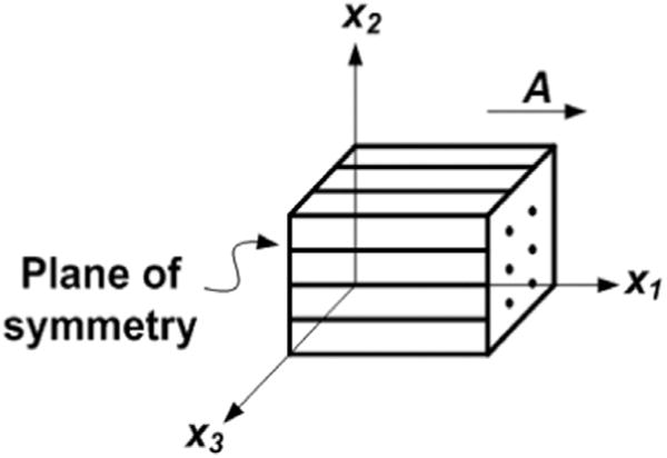
Basic model of a transversely isotropic material in Cartesian coordinates. Vector A indicates the fiber direction in the reference configuration. The plane of symmetry is perpendicular to x1.
This definition of is similar to the corresponding invariant used by Taber (2004), who described the fiber reinforcement effect in terms of Lagrange strain E. Thus, the fiber reinforcing model function H(I4, I5) can be expressed as . If we rewrite the general form of Eq. (1) in terms of , then the Cauchy stress of is
| (8) |
where ψi = ∂ψ/∂Ii (i = 1, 2, 3, 4), , and I is the identity tensor.
We consider the simple incompressible, transversely isotropic model with the strain energy function of Feng et al. (2013):
| (9) |
This model is proposed as the simplest that captures anisotropy in tension and shear in small deformations (Feng et al., 2013; Namani et al., 2012). In this model, μ is the isotropic shear modulus in a Neo Hookean strain energy function ψisotropic, and ζ and ϕ are dimensionless scaling parameters related to fiber stretch and shear. Fibers are assumed to bear load in compression as well as tension. When ϕ = 0, the model reduces to the F(I4) model.
Eqs. (8) and (9) yield the Cauchy stress:
| (10) |
where p is an arbitrary hydrostatic stress according to the incompressibility condition J = 1.
For numerical simulations of nearly incompressible material behavior, it is convenient to decompose the deformation gradient into distortional and dilatational components . The decoupled right and left Cauchy–Green deformation tensors are , . The corresponding modified principal invariants and pesudo-invariants are
| (11) |
For nearly incompressible material, a decoupled form of strain energy function is used:
| (12) |
where the volumetric term is the penalty term used to enforce near-incompressibility.
Use Eqs. (8) and (12) the corresponding Cauchy stress in terms of decoupled invariants is
where and . Note that in numerical implementation, the decoupled formulations are only applicable to incompressible materials. As for compressible material, the coupled form is recommended to prevent possible unrealistic results (Nolan et al., 2014; Sansour, 2008).
3. Responses to simple loadings
3.1. Uniaxial and biaxial loadings
Tensile (Babaei et al., 2015a,b; Jacquemoud et al., 2007; Tan et al., 2005) and biaxial mechanical tests (Sacks, 2000; Sacks, 1999) are widely used to characterize soft biological tissues. In this section, the response of a uniaxial deformation parallel (Fig. 2a) or perpendicular (b) to the fiber direction is studied. The biaxial response (Fig. 2c) of the model is also studied. If the unit vector of the fiber direction A is given as A = x1, the deformation gradient F and Cauchy stress σ are given in matrix form
| (14) |
where λi, i = 1, 2, 3, are the principal stretches. In the incompressible case, we have
| (15) |
Fig. 2.
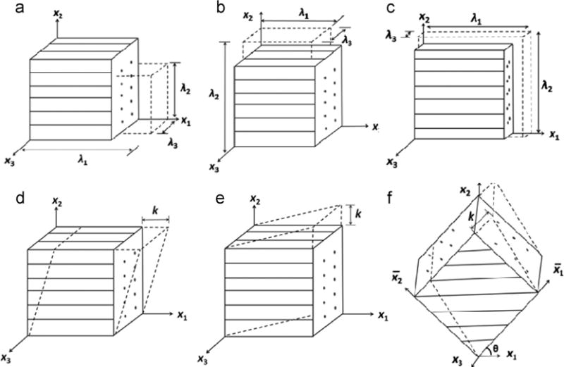
Simple deformation of a transversely isotropic material: (a) uniaxial deformation along the fiber direction; (b) uniaxial deformation perpendicular to the fiber direction; (c) biaxial deformation. (d) simple shear in the fiber direction; (e) simple shear transverse to the fiber direction; (f) general simple shear in (x1, x2) plane with shear angle θ with respect to x1 axis. λ1, λ2 are the stretch ratios, k is the magnitude of shear displacement, the cube has a unit length of 1 for each side.
The pseudo-invariants based on Eqs. (5) and (7) are
| (16) |
where indicates no shear deformation. From Eq. (8), the Cauchy stress components are
| (17) |
where p is the Lagrange multiplier constraining the material incompressibility.
3.1.1. Uniaxial loading in the fiber direction
In the case of uniaxial load in the fiber direction, σ22 = σ33 = 0, with Eqs. (15)–(17), we have
| (18) |
The non-zero Cauchy stress component σ11 (Fig. 3a) is
| (19) |
Fig. 3.
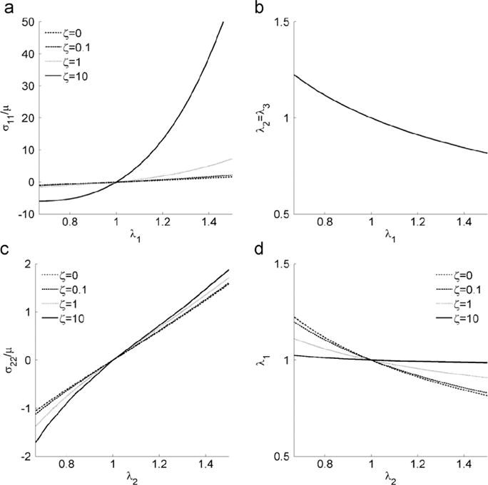
Uniaxial stress response. (a) σ11 vs. fiber stretch λ1, and (b) fiber stretch λ2 vs. λ1 when the material is under uniaxial deformation parallel to the fiber direction. (c) σ22 vs. fiber stretch λ2, and (d) fiber stretch λ1 vs.λ2 when the material is under uniaxial loading transverse to the fiber direction. The shear anisotropy parameter ϕ does not affect the stress response in these cases. The model responses for ζ =0.1 and ζ =1 are very close. An interval of [1/λmax, λmax ] is adopted for x-axis in all the plots with λmax =1.5.
From Eq. (19), we can observe that in uniaxial loading, the Cauchy stress is related to stretch by the shear modulus μ and the parameter ζ associated with the fiber stretch pseudo-invariant I4. The parameter ϕ which is associated with does not affect the Cauchy stress in uniaxial loading. The uniaxial response is a strong function of ζ (Fig. 3a), but the stretch ratios in the plane of isotropy (λ2 and λ3), which are constrained by incompressibility (Eq. (18)), are independent of the material parameters (Fig. 3b).
3.1.2. Uniaxial loading transverse to the fiber direction
When uniaxial loading is applied along the x2 axis, we have σ11 = σ33 = 0. With Eqs. (15)–(17)
| (20) |
Under the incompressibility condition λ1λ2λ3 = 1, the relationship between stretch ratios λ1 and λ2 can be obtained from Eq. (20)
| (21) |
The non-zero Cauchy stress component σ22 is
| (22) |
A numerical solution is obtained from Eqs. (21) and (22) (Fig. 3c and d).
3.1.3. Biaxial loading in the (x1, x2) plane
Taber (2004) presented an analytical solution for biaxial stretch of a transversely isotropic material. Following his approach, the response of the planar biaxial stretch of the transversely isotropic material of Eq. (9), with fibers along the x1 axis, is
| (23) |
The stress-stretch curves for equibiaxial stretch (Fig. 4a and b) reveal that the stress perpendicular to the fiber direction is not affected by fiber reinforcement. This is useful in equibiaxial calibration experiments because the material parameters ζ and μ can be determined by probing the stresses σ11 and σ22.
Fig. 4.
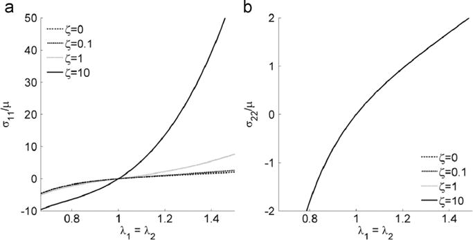
(a) σ11and (b) σ22 vs. fiber stretch λ1 = λ2, when the material is under equal biaxial deformation. An interval of [1/λmax, λmax ] is adopted for x-axis in all the plots with λmax =1.5.
Note that because, in all the above analyses, the model responses when ζ =0.1 and ζ =1 are qualitatively very similar, we use only ζ ={0, 1, 10} for illustration in the following analyses.
3.2. Shear deformations
For homogeneous shear deformation, we denote the amount of shear as the displacement magnitude k imposed on the top of a sheared unit cube. For transversely isotropic materials, the shearing deformation can be separated into (i) shear in the plane of isotropy ((x2, x3) plane) and (ii) shear in the plane perpendicular to the plane of isotropy ((x1, x2) plane). For the transversely isotropic material in Eq. (9), when shear deformation is in the plane of isotropy, I4 = I5 = 1. In this case, the fiber reinforcement effect is minimum; the material behaves like Neo Hookean material. The shear stress σ23 = μk, and the strain energy function in terms of k is . In this study, we focus on the analyses of shear deformation in a plane perpendicular to the plane of isotropy. Shearing in the direction of fibers (Fig. 2d), transverse to the fibers (e), and in an arbitrary direction in the (x1, x2) plane (f) with incompressibility constraint are analyzed. A condition of plane strain in the (x1, x2) plane is assumed for simplicity.
3.2.1. Simple shear displacement in a fiber plane
When shear deformation is produced by imposing a displacement k in the fiber direction (Fig. 2d), the deformation gradient tensor F and Cauchy–Green tensor C are
| (24) |
The corresponding pseudo-invariants I4 and I5 are
| (25) |
The corresponding Cauchy stress components are
| (26) |
The stress response as a function of k is shown in Fig. 5. We observe that ζ does not affect the Cauchy stress, which indicates that the fibers are not stretched when the shearing displacement is imposed in the fiber direction. However still captures the shearing information when k is nonzero. ϕ affects all the Cauchy stress components.
Fig. 5.
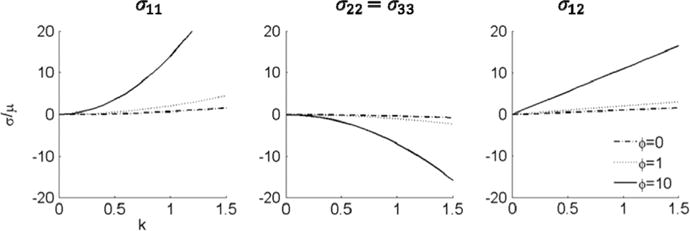
Stress response to simple shear displacement parallel to the fiber direction for ϕ=0, ϕ=1, and ϕ=10. The parameter ζ, which is related to the fiber stretch, does not influence the response. The shear stress complies with the linear response of the Neo Hookean material when ϕ=0.
If also under a plane stress condition (σ33 = 0), the Cauchy stress tensor σ is
| (27) |
If the strain energy function is written in terms of k (Eqs. (4), (9) and (25))
| (28) |
then
| (29) |
From Eqs. (27) and (28), we observe that: (i) σ11, σ22 and σ33 are even functions of k; (ii) σ12 is an odd function of k; (iii) the parameter ζ, which governs stresses due to fiber stretch, is not included in either the stress response or the strain energy change. Only the parameter ϕ affects the stress response.
3.2.2. Simple shear displacement transverse to the fiber direction
When the simple shear deformation is imposed with displacement transverse to the fiber (Fig. 2e), the deformation gradient tensor F and Cauchy–Green tensor C are
| (30) |
The corresponding pseudo-invariants I4 and I5 are
| (31) |
We observe that if the amount of shear k>0 and I4>1, the fibers are stretched. Also, is nonzero only when k is nonzero. Based on Eq. (8), the Cauchy stress is
| (32) |
The stress response as a function of k is shown in Fig. 6.
Fig. 6.
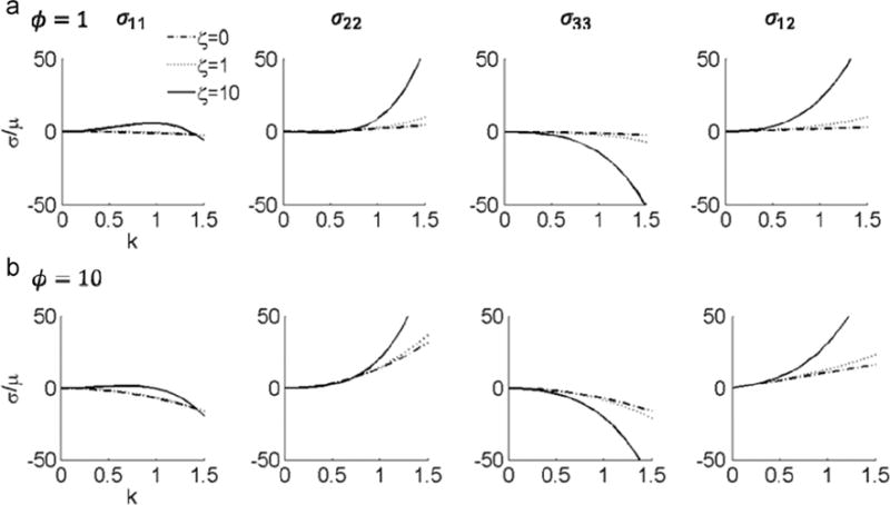
Stress response to simple shear displacement transverse to the fiber direction for ζ =0, ζ =1, and ζ =10. (a) ϕ=1, and (b) ϕ=10.
If plane stress condition is assumed (σ33 = 0), the Cauchy stress tensor σ is
| (33) |
If the strain energy function is written in terms of k (Eqs. (4), (9) and (31))
| (34) |
then
| (35) |
From Eqs. (33) and (34), we observe that: (i) σ11, σ22 and σ33 are even functions of k; (ii) σ12 is an odd function of k; (iii) both ζ and ϕ are included in the stress and strain energy term.
3.2.3. General simple shear in the (x1; x2))plane
If simple shear is applied in the (x1; x2) plane, with shearing direction in an angle θ to the x1 axis (Fig. 2f), then we set up the material coordinates following (Horgan and Saccomandi, 2005; Merodio and Ogden, 2005; Qiu and Pence, 1997):
| (36) |
where the shearing direction is parallel to axis. The deformation gradient F, and the right Cauchy-Green tensor C in the coordinates are the same as Eq. (24). Using Eq. (36) to transform F and C into (x1; x2; x3) coordinates
| (37) |
The pseudo-invariants are
| (38) |
It is easy to verify that , which captures the shearing information when k is nonzero(Merodio and Ogden, 2005). increases with k when θ is 0, , , (Fig. 7). When θ is , is a concave function, with an inflection point at k = 1. The normalized Cauchy stress in terms of material parameters ζ and ϕ and the shearing direction θ is shown in Appendix A. A plot of the Cauchy stress components σ11, σ22, σ33 and σ12 against the amount of shear k with and shows that the stress response could be non-monotonic (Fig. 8 and Fig. 9). The stress responses are monotonic when ζ is 0 or 1 and ϕ is 1. However, when ζ and ϕ become larger, especially when ζ=ϕ=10, the non-monotonic effect appears in all stress components. The nonzero components of Cauchy stress tensor in plane stress condition are also shown in Appendix A.
Fig. 7.
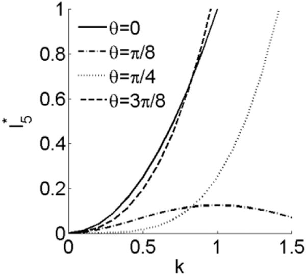
vs. k when shearing direction angle θ with respect to x1 is 0, , , . is the same when θ is 0 and .
Fig. 8.
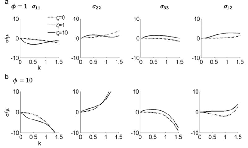
Stress response to in-plane shear displacement with shearing direction θ=π/4, for ζ =0, ζ =1, and ζ =10. (a) ϕ=1, and (b) ϕ=10.
Fig. 9.
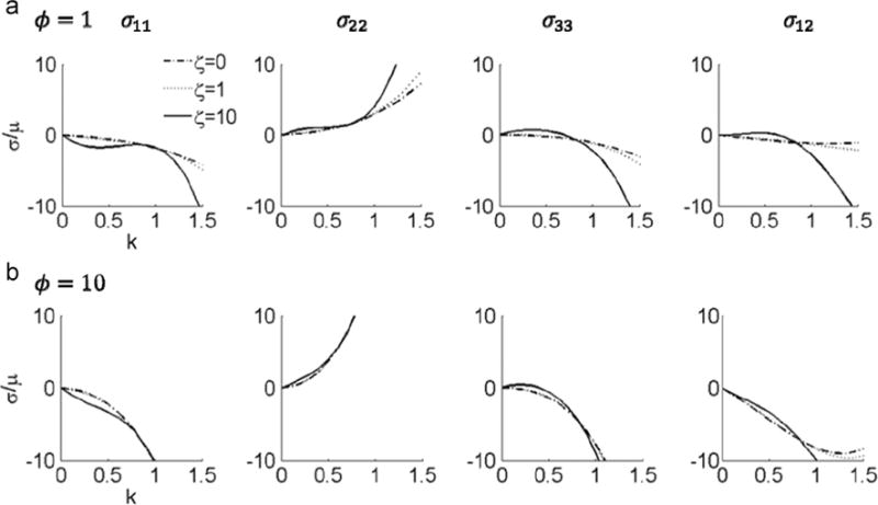
Stress response of in-plane shear displacement with shearing direction θ=3π/8, for ζ =0, ζ =1, and ζ =10. (a) ϕ=1, and (b) ϕ=10.
4. Example of data fitting
Transversely isotropic material models have been applied to study ligament and tendon tissues which have distinct fiber directions (Dourte et al., 2008; Henninger et al., 2015; Lake et al., 2010). Many tensile and biaxial tests have been done (Davis and De Vita, 2012; Henninger et al., 2015; Szczesny et al., 2012). Typical tests such as stretch along the fiber direction are usually of primary interest for ligaments and tendons. Therefore, we used data from uniaxial stretch of tendon to show the model behavior with one of the anisotropic invariants.
As an example of fitting the model of Feng et al. (2013), we fit the mechanical tests of Davis and De Vita (2012), who applied uniaxial stretch along the fiber direction of rat tail tendon fascicles. The tensile test is similar to Fig. 2a. A fitting of the data from the uniaxial stretch provides a first estimate of μ=107.66 MPa, and ζ=0.91 (Fig. 10).
Fig. 10.
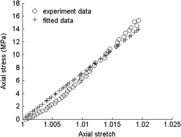
Experimental and fitted data of rat tail tendon fascicles under tensile loading along the fiber direction.
5. Discussion
5.1. Anisotropic behavior
The stress responses when the material is stretched transverse and parallel to the fiber direction (Fig. 11a, b) confirms the fiber reinforcement effect when ζ>0. The shear stress increases in a nonlinear fashion when the material is sheared transverse to the fiber direction (Fig. 11c, d). Inspection of the shear stress component σ12 in Eqs. (26) and (32) shows that the shear stresses in the two cases (shear displacement parallel or perpendicular to the fiber direction) differs by 2ζk3. Thus anisotropic behavior under finite shear is partly a result of fiber stretch, analogous to the Poynting effect.
Fig. 11.
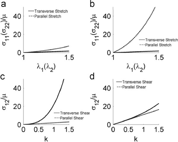
Illustration of the anisotropic behavior of the model: stress vs. stretch ratio for (a) ζ=1 and (b) ζ=10 when the material is stretched transverse/parallel to the fiber direction; and comparison of shear stress in simple shear for (c) ζ=10, ϕ=1 and (d) ζ=1, ϕ=10 when the material is sheared transverse/parallel to the fiber direction.
5.2. Strengths and limitations of transversely isotropic constitutive models
5.2.1. Uniaxial stretch in the fiber direction
Using the F(I4) model Qiu and Pence (1997) showed that when the material is loaded along fiber direction
| (39) |
Using a strain energy function analogous to the G(I5) model, Merodio and Ogden (2005) showed that when loaded in tension along fiber direction
| (40) |
Eq. (39) is identical with Eq. (19) ( is unaffected by fiber stretch). Similar results were also observed in a transversely isotropic model with F(I4) only, proposed by Horgan and Saccomandi (2005). In Eq. (40), it is clear that I5 contributes to the uniaxial response, σ11.
5.2.2. Uniaxial stretch transverse to the fiber direction
The relation between fiber stretch λ1 and λ2 in Eq. (21) is seen in the F(I4) model and the G(I5) model, from which
| (41) |
Both the F(I4) and G(I5) models have limited shortening along the fiber direction (λ1 in Fig. 3d) when stretching infinitely perpendicular to the fiber direction (λ2 in Fig. 3d). The asymptotic behavior of the H(I4; I5) model is the same as that of the F(I4) model.
5.2.3. Simple shear displacement in the fiber direction
In plane stress conditions, when ϕ = 0 the Cauchy stress tensor for the H(I4; I5) model is identical to that of the F(I4) model. If ϕ>0, each stress component is larger than that of the F(I4) model. By comparing the stress response with those from the G(I5) model:
| (42) |
we observe that the magnitudes of both σ11 and σ12 increase monotonically as k increases (σ11 is an even function and σ12 is an odd function). In Eqs. (26) and (28), we observe that the stress components and strain energy function are only related to ϕ, the parameter characterizing fiber matrix interaction. Similarly, in the G(I5) model, all stress components contain γ (Eq. (42)) which is the parameter related with fiber shear.
5.2.4. Simple shear displacement transverse to fiber direction
Similar to the case of simple shear in fiber direction, the Cauchy stress is the same when ϕ=0 but larger when ϕ>0, compared to the F(I4) model, due to fiber-matrix interactions. If we compare with the Cauchy stress tensor in a similar analysis with respect to the G(I5) model:
| (43) |
then, for plane stress, we see from Eqs. (33) and (43) that for both models: (i) σ11; σ22 and σ33 are even functions; (ii) σ12 is an odd function; (iii) σ11, σ22, and σ12 increase monotonically as k increases. However, if not in plane stress, neither σ11 nor σ22 are monotonic (Fig. 6), due to the negative term involving ζ.
5.2.5. Simple shear displacement in an arbitrary direction
Analysis of I4, I5, and C12 with respect to k and θ has been performed by Merodio and Ogden (2005). One difference worth noting is that when the fiber direction θ = π/8, I5 is convex (Merodio and Ogden, 2005) and is concave (Fig. 7) with respect to k. This illustrates the interaction between I4 and I5 when in general shear deformation. The current model confirms that differences in the direction of shear displacement can have a large influence on the stress responses (Figs. 8 and 9). A similar effect was also presented in the G(I5) model presented by Merodio and Ogden (2005). When ϕ = 0, the Cauchy stress components in Eqs. (A.5)–(A.7) are identical to the F(I4) model, but larger when ϕ>0. Compared with the results of arbitrary shear from the G(I5) model, we observe a similar pattern of σ11, σ22, and σ12 with respect to k.
5.3. Effect of anisotropic invariants in different loading conditions and implications for mechanical tests
To characterize transversely isotropic materials, it is usually necessary to estimate model parameters via mechanical tests. Although inverse methods can be used to estimate model parameters, a straightforward estimate of the model parameters via fitting experiment data is still desirable (Zhang et al., 2015). We examined the effect of each invariant by comparing the stress components from Eq. (9) to the responses of the model lacking one of the anisotropic invariants (I4 or I5):
| (44) |
The corresponding mechanical tests that are best to capture the invariant and model parameters are discussed.
5.3.1. Effect of I4 and implications for model fitting
In both uniaxial and equal biaxial tensile tests, we observe that all the stress components are only affected by parameter ζ. If the I4 term was omitted, for uniaxial stretch along the fiber direction and equal biaxial stretch, the error of σ/μ would be the same (Eqs. (19) and (23)):
| (45) |
In simple shear deformation when fiber is along the fiber direction, we observe that the stress components are not affected by I4. However, if the shear deformation is transverse to the fiber direction in the plane of (x1; x2), omitting I4 can cause error. The error depends linearly on ζ and is a non-linear function of the shear deformation, k (Eq. (32)):
| (46) |
Thus, when estimating the parameter ζ, or any parameters scaling the I4 invariant, uniaxial or biaxial stretch tests are sensible.
5.3.2. Effect of I5 and implications for model fitting
The effects of I5 in shear are captured by the modified invariant . If is not included in the model, and shear parallel to the fiber direction, the error of stress is proportional to both the parameter ϕ and the shear amplitude, k (Eq. (26)):
| (47) |
Similar analysis can be applied to simple shear deformation transverse to the fiber direction, and an analytical solution of the stress error in terms of parameter ϕ can be obtained from Eq. (32):
| (48) |
With respect to estimating parameter ϕ, considering Eq. (26), it is recommended to use shear tests parallel to the fiber direction for data fitting.
5.3.3. Remarks on mechanical testing
In estimating the five parameters of the general transversely isotropic material form (Eq. (1)), Criscione et al. (2001) developed a novel invariant sets separating physical attributes of strain. These mutually orthogonal invariants provide a unique advantage in the experimental determination of the energy functions (Criscione et al., 2001, 2000, 2002). In this study, the specific strain energy form of Eq. (9) has only three parameters. We have shown that under uniaxial loading, either along, or perpendicular to the fiber direction, or during equibiaxial stretch, only the invariant I4 is needed to model the material behavior. In shear deformation parallel to the fiber direction, only the invariant is needed to model the material behavior. Therefore, each individual parameter can be fitted separately using different mechanical testing methods. However, in shear deformation transverse to the fiber direction, both fiber stretch and fiber–matrix interactions are involved, and both invariants are needed to describe the model behavior, as they are when shear deformation is in an arbitrary direction in the (x2; x3) plane.
6. Conclusions
In this study, we explored the response to large deformations of a transversely isotropic model with both I4 and I5 invariants. A comparison of the model behavior to that of transversely isotropic models with only I4 invariant showed similar responses to stretch parallel or perpendicular to the fiber direction. However, the model with both invariants showed distinctly different behavior under shear deformation.
Analytical solutions exhibited clear nonlinear anisotropic behavior in both stretch and shear deformation. The material model exhibited the expected increase in tensile stiffness in the fiber direction, as well as a larger shear modulus when sheared in the plane containing fibers, relative to shear in the plane of isotropy. Nonlinear stiffening was seen for shear displacement perpendicular to the fiber direction. This behavior is useful for modeling and simulations of many soft biological tissues such as brain white matter, muscle, and tendon.
Analytical solutions of the model with both I4 and I5 invariants indicated that individual parameters, such as ζ and ϕ, could be characterized separately by tensile and shear tests. Typical mechanical testing procedures such as biaxial (Sacks, 2000; Sacks, 1999), rheometric (Hrapko et al., 2008) or shear testing (Namani et al., 2012; Rashid et al., 2013) can be utilized to characterize the parameters for specific soft tissues with transversely isotropic behavior. Parameter fitting based on data acquired from these mechanical tests can be used for first approximation of the model parameters. Although some simple mechanical tests can be fully modeled using only one invariant, loading conditions such as shear transverse to the fiber direction can be described only if both are included.
Acknowledgments
The authors would like to thank Dr. Larry A. Taber, Dr. Barna Szabo, Dr. Yunfei Shi, Dr. Spencer Lake, and Dr. Chunghao Lee for helpful discussions. We acknowledge support from Jiangsu Province (Grant BK20140356, YF), the Chinese National Natural Science Foundation (Grant 61503267, YF), the SRF for ROCS, SEM (Grant K511701515, YF), the NIH (Grants R01 NS055951 (PVB) and R01 HL109505 (GMG)), the NIH and NSF jointly though grant NSF U01 EB016422 (GMG), the NSF (Grant CMMI-1332433, PVB), and the Chinese Ministry of Education through a Changjiang Scholar Award (GMG).
Appendix A
The Cauchy stress components of the general simple shear in the (x1; x2) plane can be obtained from Eqs. (8) and (38). We normalized each stress component with respect to shear modulus μ. With short-handed notations c = cos θ, s = sin θ for simplicity, the corresponding normalized Cauchy stress components are
| (A.1) |
| (A.2) |
| (A.3) |
| (A.4) |
With plane stress condition (σ33 = 0), the nonzero components of Cauchy stress tensor σ are
| (A.5) |
| (A.6) |
| (A.7) |
References
- Babaei B, Abramowitch SD, Elson EL, Thomopoulos S, Genin GM. A discrete spectral analysis for determining quasi-linear viscoelastic properties of biological materials. J R Soc Interface/R Soc. 2015a;12 doi: 10.1098/rsif.2015.0707. [DOI] [PMC free article] [PubMed] [Google Scholar]
- Babaei B, Davarian A, Pryse KM, Elson EL, Genin GM. Efficient and optimized identification of generalized Maxwell viscoelastic relaxation spectra. J Mech Behav Biomed Mater. 2015b;55:32–41. doi: 10.1016/j.jmbbm.2015.10.008. [DOI] [PMC free article] [PubMed] [Google Scholar]
- Criscione C, Douglas JS, Hunter ACW. Physically based strain invariant set for materials exhibiting transversely isotropic behavior. J Mech Phys Solids. 2001;49:871–897. [Google Scholar]
- Chatelin S, Deck C, Willinger R. An anisotropic viscous hyperelastic constitutive law for brain material finite-element modeling. J Biorheol. 2012:1–12. [Google Scholar]
- Criscione JC, Humphrey JD, Douglas AS, Hunter WC. An invariant basis for natural strain which yields orthogonal stress response terms in isotropic hyperelasticity. J Mech Phys Solids. 2000;48:2445–2465. [Google Scholar]
- Criscione JC, McCulloch AD, Hunter WC. Constitutive framework optimized for myocardium and other high-strain, laminar materials with one fiber family. J Mech Phys Solids. 2002;50:1681–1702. [Google Scholar]
- Davis FM, De Vita R. A nonlinear constitutive model for stress relaxation in ligaments and tendons. Ann Biomed Eng. 2012;40:2541–2550. doi: 10.1007/s10439-012-0596-2. [DOI] [PubMed] [Google Scholar]
- Destrade M, Horgan CO, Murphy JG. Dominant negative Poynting effect in simple shearing of soft tissues. J Eng Math. 2015;95:87–98. [Google Scholar]
- Destrade M, Mac Donald B, Murphy JG, Saccomandi G. At least three invariants are necessary to model the mechanical response of incompressible, transversely isotropic materials. Comput Mech. 2013;52:959–969. [Google Scholar]
- Dourte LM, Kuntz AF, Soslowsky LJ. Twenty-five years of tendon and ligament research. J Orthop Res: Off Publ Orthop Res Soc. 2008;26:1297–1305. doi: 10.1002/jor.20646. [DOI] [PubMed] [Google Scholar]
- Feng Y, Okamoto RJ, Namani R, Genin GM, Bayly PV. Measurements of mechanical anisotropy in brain tissue and implications for transversely isotropic material models of white matter. J Mech Behav Biomed. 2013;23:117–132. doi: 10.1016/j.jmbbm.2013.04.007. [DOI] [PMC free article] [PubMed] [Google Scholar]
- Gasser TC, Ogden RW, Holzapfel GA. Hyperelastic modelling of arterial layers with distributed collagen fibre orientations. J R Soc Interface. 2006;3:15–35. doi: 10.1098/rsif.2005.0073. [DOI] [PMC free article] [PubMed] [Google Scholar]
- Henninger HB, Valdez WR, Scott SA, Weiss JA. Elastin governs the mechanical response of medial collateral ligament under shear and transverse tensile loading. Acta Biomater. 2015;25:304–312. doi: 10.1016/j.actbio.2015.07.011. [DOI] [PMC free article] [PubMed] [Google Scholar]
- Holzapfel GA. Nonlinear Solid Mechanics. Vol. 75. Wiley John & Sons; 2000. p. 235. [Google Scholar]
- Horgan CO, Murphy JG. Reverse Poynting effects in the torsion of soft biomaterials. J Elast. 2015;118:127–140. [Google Scholar]
- Horgan CO, Saccomandi G. A new constitutive theory for fiber-reinforced incompressible nonlinearly elastic solids. J Mech Phys Solids. 2005;53:1985–2015. [Google Scholar]
- Hrapko M, van Dommelen JAW, Peters GWM, Wismans J. Characterisation of the mechanical behaviour of brain tissue in compression and shear. Biorheology. 2008;45:663–676. [PubMed] [Google Scholar]
- Humphrey JD. Continuum Mechanics, Cardiovascular Solid Mechanics. Springer; New York: 2002. pp. 68–106. [Google Scholar]
- Jacquemoud C, Bruyere-Garnier K, Coret M. Methodology to determine failure characteristics of planar soft tissues using a dynamic tensile test. J Biomech. 2007;40:468–475. doi: 10.1016/j.jbiomech.2005.12.010. [DOI] [PubMed] [Google Scholar]
- Lake SP, Miller KS, Elliott DM, Soslowsky LJ. Tensile properties and fiber alignment of human supraspinatus tendon in the transverse direction demonstrate inhomogeneity, nonlinearity, and regional isotropy. J Biomech. 2010;43:727–732. doi: 10.1016/j.jbiomech.2009.10.017. [DOI] [PMC free article] [PubMed] [Google Scholar]
- Lu J, Zhang L. Physically motivated invariant formulation for transversely isotropic hyperelasticity. Int J Solids Struct. 2005;42:6015–6031. [Google Scholar]
- Merodio J, Ogden RW. Instabilities and loss of ellipticity in fiber-reinforced compressible non-linearly elastic solids under plane deformation. Int J Solids Struct. 2003a;40:4707–4727. [Google Scholar]
- Merodio J, Ogden RW. Material instabilities in fiber-reinforced nonlinearly elastic solids under plane deformation. Arch Mech. 2003b;55 [Google Scholar]
- Merodio J, Ogden RW. Mechanical response of fiber-reinforced incompressible non-linearly elastic solids. Int J Non-Linear Mech. 2005;40:213–227. [Google Scholar]
- Morrow DA, Haut Donahue TL, Odegard GM, Kaufman KR. Transversely isotropic tensile material properties of skeletal muscle tissue. J Mech Behav Biomed Mater. 2010;3:124–129. doi: 10.1016/j.jmbbm.2009.03.004. [DOI] [PMC free article] [PubMed] [Google Scholar]
- Murphy JG. Transversely isotropic biological, soft tissue must be modelled using both anisotropic invariants. Eur J Mech A—Solid. 2013;42:90–96. [Google Scholar]
- Namani R, Feng Y, Okamoto RJ, Jesuraj N, Sakiyama-Elbert SE, Genin GM, Bayly PV. Elastic characterization of transversely isotropic soft materials by dynamic shear and asymmetric indentation. J Biomech Eng. 2012;134:061004. doi: 10.1115/1.4006848. [DOI] [PMC free article] [PubMed] [Google Scholar]
- Ning XG, Zhu QL, Lanir Y, Margulies SS. A transversely isotropic viscoelastic constitutive equation for Brainstem undergoing finite deformation. J Biomech Eng—Trans ASME. 2006;128:925–933. doi: 10.1115/1.2354208. [DOI] [PubMed] [Google Scholar]
- Nolan DR, Gower AL, Destrade M, Ogden RW, McGarry JP. A robust anisotropic hyperelastic formulation for the modelling of soft tissue. J Mech Behav Biomed. 2014;39:48–60. doi: 10.1016/j.jmbbm.2014.06.016. [DOI] [PubMed] [Google Scholar]
- Ogden RW, Saccomandi G, Sgura I. Fitting hyperelastic models to experimental data. Comput Mech. 2004;34:484–502. [Google Scholar]
- Pierce DM, Ricken T, Holzapfel GA. A hyperelastic biphasic fibre-reinforced model of articular cartilage considering distributed collagen fibre orientations: continuum basis, computational aspects and applications. Comput Methods Biomech Biomed Eng. 2013;16:1344–1361. doi: 10.1080/10255842.2012.670854. [DOI] [PubMed] [Google Scholar]
- Polignone DA, Horgan CO. Cavitation for incompressible anisotropic nonlinearly elastic spheres. J Elast. 1993;33:27–65. [Google Scholar]
- Qiu GY, Pence TJ. Remarks on the behavior of simple directionally reinforced incompressible nonlinearly elastic solids. J Elast. 1997;49:1–30. [Google Scholar]
- Rashid B, Destrade M, Gilchrist MD. Mechanical characterization of brain tissue in simple shear at dynamic strain rates. J Mech Behav Biomed. 2013;28:71–85. doi: 10.1016/j.jmbbm.2013.07.017. [DOI] [PubMed] [Google Scholar]
- Sacks M. Biaxial mechanical evaluation of planar biological materials. J Elast. 2000;61:199–246. [Google Scholar]
- Sacks MS. A method for planar biaxial mechanical testing that includes in-plane shear. J Biomech Eng. 1999;121:551–555. doi: 10.1115/1.2835086. [DOI] [PubMed] [Google Scholar]
- Sansour C. On the physical assumptions underlying the volumetric-isochoric split and the case of anisotropy. Eur J Mech A—Solid. 2008;27:28–39. [Google Scholar]
- Schröder J, Neff P, Balzani D. A variational approach for materially stable anisotropic hyperelasticity. Int J Solids Structures. 2005;42:4352–4371. [Google Scholar]
- Spencer AJM. Continuum Theory of the Mechanics of Fibre-Reinforced Composites, CISM International Centre for Mechanical Sciences. 1. Springer-Verlag; Wien: 1984. p. 284. [Google Scholar]
- Swedberg AM, Reese SP, Maas SA, Ellis BJ, Weiss JA. Continuum description of the Poisson’s ratio of ligament and tendon under finite deformation. J Biomech. 2014;47:3201–3209. doi: 10.1016/j.jbiomech.2014.05.011. [DOI] [PMC free article] [PubMed] [Google Scholar]
- Szczesny SE, Peloquin JM, Cortes DH, Kadlowec JA, Soslowsky LJ, Elliott DM. Biaxial tensile testing and constitutive modeling of human supraspinatus tendon. J Biomech Eng. 2012;134 doi: 10.1115/1.4005852. 21004-NaN. [DOI] [PMC free article] [PubMed] [Google Scholar]
- Taber LA. Nonlinear Theory of Elasticity: Applications in Biomechanics. World Scientific; River Edge, NJ: 2004. [Google Scholar]
- Tan EPS, Ng SY, Lim CT. Tensile testing of a single ultrafine polymeric fiber. Biomaterials. 2005;26:1453–1456. doi: 10.1016/j.biomaterials.2004.05.021. [DOI] [PubMed] [Google Scholar]
- Thomopoulos S, Genin GM. Tendon and ligament biomechanics. Orthop Biomech. 2012;49 [Google Scholar]
- Velardi F, Fraternali F, Angelillo M. Anisotropic constitutive equations and experimental tensile behavior of brain tissue. Biomech Model Mechanobiol. 2006;5:53–61. doi: 10.1007/s10237-005-0007-9. [DOI] [PubMed] [Google Scholar]
- Weiss JA, Maker BN, Govindjee S. Finite element implementation of incompressible, transversely isotropic hyperelasticity. Comput Methods Appl Mech Eng. 1996;135:107–128. [Google Scholar]
- Zhang W, Feng Y, Lee CH, Billiar KL, Sacks MS. A generalized method for the analysis of planar biaxial mechanical data using tethered testing configurations. J Biomech Eng. 2015;137:064501. doi: 10.1115/1.4029266. [DOI] [PMC free article] [PubMed] [Google Scholar]


