

Abstract
Gastrointestinal stimulator implants have recently shown positive results in helping obese patients lose weight. However, to place the implant, the patient currently needs to undergo an invasive surgical procedure. Our team is aiming for a less invasive procedure to stimulate the stomach with a gastrostimulator. Attempts covered fully endoscopic implantation and, more recently, we have focussed on a single incision laparoscopic procedure. Whatever the chosen implantation solution, the electronic design of the implant system shares many challenges. This paper covers the work achieved to meet these.
Key Words: cortical electrical stimulation, stimulator characterization, stimulator model, electrode model, output impedance
Obesity has reached epidemic proportions with 2.1 billion overweight adults (Body Mass Index above 25) and 600 million obese adults (BMI above 30) worldwide.1-3 Obesity is commonly associated with major health problems and each year, obesity is responsible for millions of deaths.2-4 Bariatric surgery can be efficient in dealing with this issue but they are invasive operations performed either by multi-incision laparoscopy or even open surgery. Besides, they represent a large portion of annual health-care expenditures and are limited to patients whose BMI is superior to 35.5 Gastrostimulation has been demonstrated to induce weight loss in humans.6-8 However, current gastrostimulators are bulky and are implanted by multi-incision laparoscopy, a relatively expensive and invasive procedure. This project aims to implant the device through a less invasive procedure. Our designs have covered fully endoscopic procedure and, more recently, a single incision laparoscopic procedure. Whatever the chosen implantation solution, the electronic design of these gastrostimulators shares many challenges. From an engineering point of view, compared to currently available stimulators, we are aiming to:
reduce the dimensions and weight of the device while protecting it from its environment,
provide a stable anchoring,
provide a reliable implantation method to place and attach the device.
This paper presents the design and implementation of these novel gastrostimulators with validation on a test bench and ex-vivo
Materials and Methods
A. Electronic design
The stimulation protocol is based on that of the Enterra by Medtronic, which has already achieved good results with electrodes near the pylorus in humans,7,8 and at the pylorus in dogs.9 The protocol consists of sending trains of current pulses for two seconds every five seconds. Each train is composed of 5 mA pulses, lasting 330 μs, repeated every 25 ms. Fig. 1 shows a block diagram of the implant, including a rechargeable battery, a voltage boost (to raise the battery voltage), a microcontroller (for the timing and circuit synchronisation) and the stimulation circuit. Briefly, the current source is based on an operational amplifier driving the gate of a transistor. A microcontroller is used to drive the amplifier at the desired frequency. We expect in situ impedance ranging from 200 to 800 Ω 10-14 A 2.2 μF blocking capacitor will ensure a null mean charge. A depletion transistor is used to limit the discharge current to at most 20% of the stimulation current. During the stimulation phase, the depletion transistor is blocked and the current goes through the electrodes. During the discharge period, the capacitor discharges through the stomach impedance and the depletion transistor. Finally, a boost circuit powered by a 3.5 V battery supplies the power to the circuit. The layout was drawn on a 16 mm diameter substrate. The stimulation occurs at the pyloric sphincter, which was chosen to anchor the device. Two cylinders linked by a flexible body form the implant and are designed to be endoscopically placed on each side of the pylorus. One cylinder hosts the electronics and delivers the stimulation through surface electrodes (see Fig. 2). The other contains the power supply.
Fig 1.

Block diagram of the implant
Fig 2.

Anchoring method of implant at pylorus
B. Choice of materials
To minimise the device’s overall weight and volume, we have opted to protect the electronics by encapsulation with silicone rubber. In the case that the implant is placed in the stomach, it should also resist its acidic environment. This method is well-established for human implants,15 but has never been used for devices operating in the stomach, where the very low pH presents a new challenge. The success of this protection relies on the long-term stability of the bond between the encapsulant and the substrate on which the circuit is built.16 Therefore, several couples of substrate and adhesive were tested following PEK Donaldson’s method.17
The long-term stability of the adhesive bond between several couples of substrate and adhesive immersed in simulated gastric liquid was the topic of a previous publication.18 Two silicone rubbers were tested on typical implant substrates at worst-case stomach pH. Lap-shear tests showed the MED4-4220/alumina couple offered the best adhesion with a mean time to failure (MTF) of 30 days at 100°C, resulting in a large predicted MTF at body temperature (7 years). The MED4-4220/FR4 couple also had a high MTF of 25.1 days (6 years). FR4 substrate was chosen to manufacture prototypes of the implant as FR4 substrates can be ordered directly from usual commercial suppliers.
C. Manufacturing of the implant
Cleanliness during the encapsulation process strongly influences the implant’s lifetime.16 Briefly, the cleaner the circuit and the substrate, the higher the osmotic gradient, should water vapour, which will rapidly permeate the encapsulation layer, find a condensation site. Liquid water formations would therefore be limited, and what would form would be highly resistive, hence limiting further loss of adhesion, and corrosion. Therefore, the devices were thoroughly cleaned using isopropanol and alkaline cleaning solution, and rinsed in flowing de-ionised water. A dedicated mould has been built to encapsulate the implant. The design of the mould allows a protection layer of silicone rubber of 2 mm above the components and of 0.5 mm above the substrate on the side without components. The encapsulation was realised using a vacuum centrifuge. The design of the mould allows the 3 × 3 mm surface electrodes to remain uncovered by silicone rubber. The encapsulate implant, which is 17 mm diameter and 5.5 mm thick, allows endoscopic passage through the mouth.
The battery was dip-coated with Dow Corning 3140 silicone rubber and the procedure was repeated until the layer of the silicone rubber was sufficiently thick. Each new affixed layer of silicone rubber was degassed and dried before the next dip. DC3140 was selected for dip-coating as it forms a thin layer and dries in a few minutes in a humid environment at room temperature. This silicone rubber is, however, not authorised for human implantation. It was used only for this prototyping stage and no adhesion tests were performed between DC3140 and the material of the battery case.
Low temperature sterilisation using gas plasma technology (Sterrad sterilisation) was used for the implant and the battery, avoiding a potential melding of the silicone rubber and degradation of the battery. Steam sterilisation (autoclave) was used for all the material not based on silicone rubber, and that could withstand the elevated temperature
Results
A. Stimulation protocol and load range
To validate the stimulation protocol, an implant was used in continuous mode (trains repeated without interruption) with a load between 200 and 800 Ω. The implant delivers 5 mA pulses, 330 μs wide with a period of 25 ms. The trains last 2 s and are repeated every 5 second, giving 12 bursts per minute. Fig. 3 shows two successive trains of pulses (blue curve) and the power supply voltage (green curve). The behaviour of the implant was validated with a load modelled by a resistor connected between the electrodes. We started with a 200 Ω load, increased in steps of 200 Ω. The implant worked properly from 200 to 1200 Ω, i.e. in a larger range that the one required (between 200 and 800 Ω): correct pulses were delivered and a complete discharge of the current was achieved within the 25 ms. From 1400 Ω, the stimulation waveform is affected, with longer pulses duration and lower stimulating current.
Fig 3.

Monitoring of the pulses train
B. Power requirement
The power consumed by the implant is due to the microcontroller (71 %), the output stage (27 %) and the amplifier (2%). Note that the output stage includes a boost DC/DC converter to increase the battery voltage (around 3.3 V) to the 8 V required for the stimulation. The chosen boost (LT3464) uses a discontinuous mode.
1. Output stage consumption (stimulation phase)
Fig. 4 shows that during a stimulation pulse, the instantaneous current from the battery reaches peaks of 75 mA. The boost is therefore working in a discontinuous mode, as expected. Therefore, during pulse delivery, an average current of 16 mA is drawn from the battery (see red curve on Fig. 4).
Fig 4.
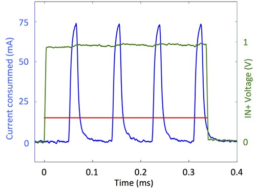
Current peaks and average current consumed during stimulation: the green curve is the input voltage of the amplifier, the blue curve represents the instantaneous current consumption and red curve is the average current consumption computed over the current peaks.
With its output voltage of 3.5 V (directly measured at the battery output) the battery outputs a power of 56 mW. The output voltage and output current of the boost are respectively 8 V and 5 mA, hence the power delivered is 40 mW, leading to an efficiency of 71% for the boost during stimulation.
The discontinuous mode of the boost induces important current peaks demand to the battery cell. Unfortunately commercially available implantable battery cells are not able to deliver such important peaks. The resulting output voltage drop can go below the minimum operating voltage of 2.1 V and cause stimulation to abort, as shown in Fig. 5. An additional capacitor is placed in parallel with the battery to smooth the current spikes.
Fig 5.
2nd stimulation aborted due to voltage drops at the battery cell without added capacitor
2. Output stage consumption (quiet phase)
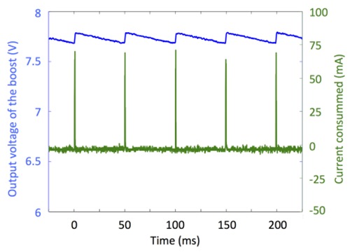
Fig. 6 shows that the instantaneous current consumption of the boost also reaches peaks up to 75 mA, repeated at 20 Hz.
Fig 6.

Output voltage of the boost (blue curve) and current consumption (green curve) during quite phase
3. Implant consumption and lifetime
The implant total average current equals 370 μA. It is mainly due to the microcontroller (264 μA) and the output stage (84 μA during stimulation and 17 μA during rest). Note that quiescent currents of the components were too small to measure and were therefore derived from their datasheets.
Commercially available batteries from EaglePicher, Greatbach, Quallion and Saft were considered. And we found energetic densities no higher than 1595 mWh/cm3. Using this kind of battery, the implant lifetime would reach 51 days per cubic centimetre
C. Minimum required voltage
Since the implant is powered by a battery cell, the input power voltage is constantly decreasing. Fig. 7 shows the behaviour of the implant when the battery voltage decreases. When the battery voltage falls below 2.1 V no pulse is delivered anymore. At 2.1 V, the microcontroller is not capable of delivering the desired output values. At 2 V, the boost is not capable of working properly. The implant stopped working without inducing any damages
Fig 7.

Effect of the decrease of the battery cell voltage (purple) on the stimulation (blue) and the boost voltage (red).
D. Ex-vivo validation
The stimulator was tested ex-vivo on an animal model to prove the functionality of the stimulator and verify the correct propagation of stimuli. The stimulator was surgically implanted in a dog cadaver. Needle recording electrodes (Biopac – Stim Ndl Electrode, BNC – ELSTM2) were implanted near the stimulation site and connected to an oscilloscope (Tektronix TDS 1002). Printed FR4 substrates were ordered from Eurocircuits and recessed surface electrodes were used. The stimulator was successfully attached to the stomach. Stimulation pulses were observed using the oscilloscope (Fig. 8). This confirms the functionality of the electronic design and a good contact between the implant’s electrodes and the tissue.
Fig 8.

Measured pulses during the stimulation of the dog’s cadaver stomach
Recordings were realised with the needle electrodes positioned near the stimulation site. The exact position of the electrodes was not measured as this test did not aim to study the amplitude of the pulses. Correct trains of pulses, i.e. at the correct frequency, were observed near the stimulation site (see Fig. 8). This is indicative of a good contact between the implant electrodes and the stomach tissue, good propagation of the pulses and that the implant works properly in an ex-vivo environment
Discussion
We presented design and implementation of a gastrostimulator, allowing to reduce the dimensions and weight of the devices while still protecting them from the low pH stomach environment mimicked in a bench test. The method was validated on a test bench and ex-vivo. In-vivo validation of the stimulator has also been achieved on several dogs and will be detailed in a future extended article.
Future steps will assess the effect of the gastric stimulation in vivo. Active stimulators will be surgically implanted in dogs to assess the weight loss during stimulation. Different stimulation protocols will be tested during the experiment. The impact on the gastric slow waves, specific hormones and the amount of food ingested will be monitored to assess the physiological impact of the selected stimulation protocol.
Acknowledgement
The authors thank Mr. Bruno Tartini and Mr. Geoffrey Vanbienne for their contribution to the lap-shear tests.
Contributor Information
Anne Vanhoestenberghe, Email: a.vanhoest@ucl.ac.uk.
Vincent Huberty, Email: Vincent.Huberty@erasme.ulb.ac.be.
Martin Hiernaux, Email: Martin.Hiernaux@endotools.be.
Nicolas Cauche, Email: Nicolas.Cauche@ulb.ac.be.
Nicolas Julémont, Email: njulemon@ulb.ac.be.
Adrien Debelle, Email: addebell@ulb.ac.be.
François Huberland, Email: Francois.Huberland@ulb.ac.be.
Vicente Acuña, Email: Vicente.Acuna.Otarola@ulb.ac.be.
Carmen Godfraind, Email: Carmen.Godfraind@ulb.ac.be.
Jacques Devière, Email: Jacques.Deviere@erasme.ulb.ac.be.
Alain Delchambre, Email: Alain.Delchambre@ulb.ac.be.
Pierre Mathys, Email: pmathys@ulb.ac.be.
Antoine Nonclercq, Email: anoncler@ulb.ac.be.
References
- 1.Finucane MM, Stevens GA, Cowan MJ, et al. National, regional, and global trends in body-mass index since 1980: systematic analysis of health examination surveys and epidemiological studies with 960 country-years and 9.1 million participants. Lancet. 2011;377(9765):557-67. doi: 10.1016/S0140-6736(10)62037-5. [DOI] [PMC free article] [PubMed] [Google Scholar]
- 2.Dobbs R., Sawers C., Thompson, et al. Overcoming obesity: An initial economic analysis. McKinsey Global Institute; 2014. [Google Scholar]
- 3.Ng M, Fleming T, Robinson M, et al. Global, regional, and national prevalence of overweight and obesity in children and adults during 1980 – 2013 : a systematic analysis for the Global Burden of Disease Study. Lancet. 2014. Aug 30;384(9945):766-81. doi: 10.1016/S0140-6736(14)60460-8. [DOI] [PMC free article] [PubMed] [Google Scholar]
- 4.Drieskens S, Van der Heyden J, Demarest S, Tafforeau J. Is the different time trend (1997-2008) of the obesity prevalence among adults in the three Belgian regions associated with lifestyle changes? Archives of Public Health/Archives Belges de Santé Publique, 2014;72:18 doi.org/10.1186/2049-3258-72-18. [DOI] [PMC free article] [PubMed] [Google Scholar]
- 5.Weiner JP, Goodwin SM, Chang H-Y, et al. Impact of Bariatric Surgery on Health Care Costs of Obese Persons: A 6-Year Follow-up of Surgical and Comparison Cohorts Using Health Plan Data. JAMA Surg 2013;148:555-62. doi: 10.1001/jamasurg.2013.1504. [DOI] [PubMed] [Google Scholar]
- 6.Hasler WL. Methods of gastric electrical stimulation and pacing: a review of their benefits and mechanisms of action in gastroparesis and obesity. Neurogastroenterol Motil 2009;21:229-43. doi: 10.1111/j.1365-2982.2009.01277.x. [DOI] [PubMed] [Google Scholar]
- 7.Cigaina V. Long-term follow-up of gastric stimulation for obesity: the Mestre 8-year experience. Obes Surg. 2004;14 Suppl 1:S14-22. [DOI] [PubMed] [Google Scholar]
- 8.Shikora SA. “What are the yanks doing?” the US experience with implantable gastric stimulation (IGS) for the treatment of obesity—update on the ongoing clinical trials. Obes Surg. 2004. Sep;14 Suppl 1:S40-8. [DOI] [PubMed] [Google Scholar]
- 9.Xu X, Zhu H, Chen JDZ. Pyloric electrical stimulation reduces food intake by inhibiting gastric motility in dogs. Gastroenterology. 2005. Jan;128(1):43-50. [DOI] [PubMed] [Google Scholar]
- 10.Ayinala S, Batista O, Goyal A, et al. Temporary gastric electrical stimulation with orally or PEG-placed electrodes in patients with drug refractory gastroparesis. Gastrointest Endosc. 2005. Mar;61(3):455-61. http://doi.org/10.1016/S0016-5107(05)00076-3 [DOI] [PubMed] [Google Scholar]
- 11.Deb S, Tang S-J, Abell TL, et al. An endoscopic wireless gastrostimulator (with video). Gastro-intestinal Endoscopy, 2012;75:411-5, 415.e1. http://doi.org/10.1016/j.gie.2011.09.052 [DOI] [PMC free article] [PubMed] [Google Scholar]
- 12.Elfvin A, Andersson S, Abrahamsson, et al. Percutaneous implantation of gastric electrodes – A novel technique applied in animals and patients. Neurogastroenterol Motil 2007;19:103-9. http://doi.org/10.1111/j.1365-2982.2006.00858 .x [DOI] [PubMed] [Google Scholar]
- 13.Familoni BO, Abell TL, Nemoto D, Voeller G, Johnson B. Electrical Stimulation at a Frequency Higher than Basal Rate in Human Stomach. Dig Dis Sci 1997;42:885-91. http://doi.org/ 10.1023/A:1018804128695 [DOI] [PubMed] [Google Scholar]
- 14.McCallum RW, Lin Z, Forster J, Roeser K, Hou Q, Sarosiek I. Gastric Electrical Stimulation Improves Outcomes of Patients With Gastroparesis for up to 10 Years. Clin Gastroenterol Hepatol 2011;9:314-9.e1. doi: 10.1016/j.cgh.2010.12.013. [DOI] [PubMed] [Google Scholar]
- 15.Brindley GS. The first 500 sacral anterior root stimulators: implant failures and their repair. Paraplegia 1995;33:5-9. doi:10.1038/sc.1995.3 [DOI] [PubMed] [Google Scholar]
- 16.Vanhoestenberghe A, Donaldson N. Corrosion of silicon integrated circuits and lifetime predictions in implantable electronic devices. J Neural Eng 2013. Jun;10(3):031002 doi: 10.1088/1741-2560/ 10/3/031002. [DOI] [PubMed] [Google Scholar]
- 17.Donaldson PEK. Aspects of silicone rubber as encapsulant for neurological prostheses. Part 4: Two-part rubbers. Med Biol Eng Comput 1997;35:283-6. [DOI] [PubMed] [Google Scholar]
- 18.Lonys L, Vanhoestenberghe A, Julémont N, et al. Silicone rubber encapsulation for an endoscopically implantable gastrostimulator. Med Biol Eng Comput 2015;53:319–29. http://doi.org/10.1007/s 11517-014-1236-9. [DOI] [PubMed] [Google Scholar]