Abstract
We study the effect of turnover of cross-linkers, motors, and filaments on the generation of a contractile stress in a network of filaments connected by passive cross-linkers and subjected to the forces exerted by molecular motors. We perform numerical simulations where filaments are treated as rigid rods and molecular motors move fast compared to the time scale of an exchange of cross-linkers. We show that molecular motors create a contractile stress above a critical number of cross-linkers. When passive cross-linkers are allowed to turn over, the stress exerted by the network vanishes due to the formation of clusters. When both filaments and passive cross-linkers turn over, clustering is prevented and the network reaches a dynamic contractile steady state. A maximum stress is reached for an optimum ratio of the filament and cross-linker turnover rates. Taken together, our work reveals conditions for stress generation by molecular motors in a fluid isotropic network of rearranging filaments.
The cell cortical cytoskeleton is essential in processes involving cell shape changes [1, 2].In the cortex, myosin molecular motors are assembled in a bipolar filamentous structure which binds to actin filaments and generates forces by consuming the chemical energy of the hydrolysis of adenosine triphosphate. The action of myosin motors result in the generation of an active, contractile stress whose spatial distribution in the cortex plays a key role in cellular morphogenetic processes [3–5].
In living cells, passive and active cross-linkers and actin filaments are continuously exchanged between the cortex and the cytosol [1]. As a result, cytoskeletal networks can release elastic stresses stored in the network and undergo large-scale flows. Significant progress has been achieved to understand stress generation in networks with permanent filaments and fixed or unbinding cross-linkers, through in vitro studies and a theoretical analysis of actomyosin network [6–15]. It is unclear, however, what is the role of turnover in stress generation and how filament networks can simultaneously rearrange and exert a permanent internal active stress. In vivo experiments suggest that the rate of turnover is a major determinant of force generation by actomyosin networks [16, 17].
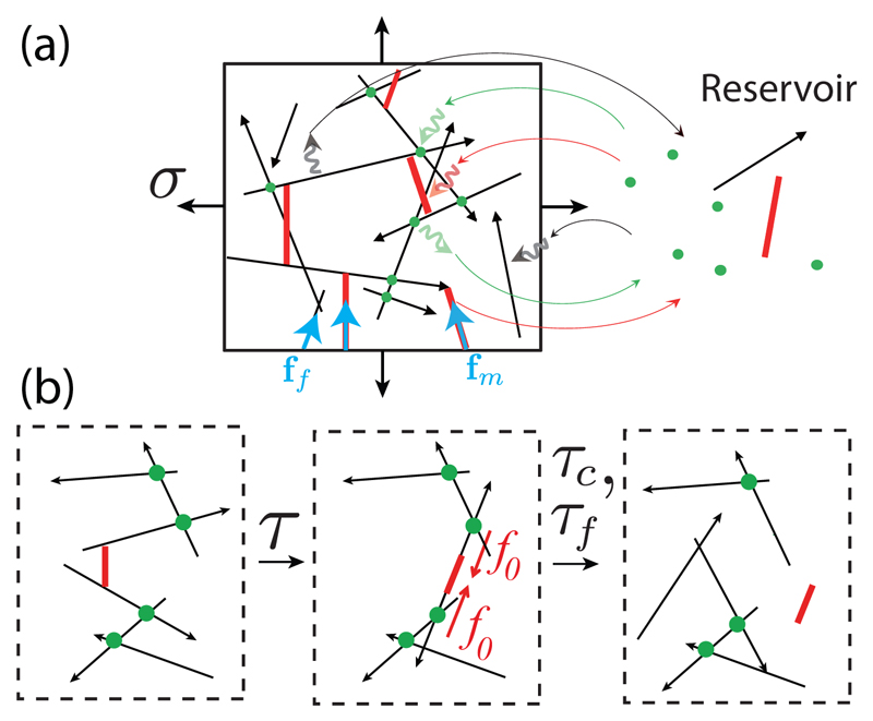
We ask here how the rate of turnover of passive cross-linkers and actin filaments influence the active stress generated by motors in the network. We study a simplified mechanical model for a cytoskeletal network in two dimensions whose constituents are turning over [Fig. 1(a)]. Filaments and motors are treated as rigid rods. Filaments have a polarity represented by arrows in Fig. 1. Passive cross-linkers are assumed to be pointlike and constrain the position of the filaments on which they are attached. Filaments are able to rotate freely around the cross-linker position and around motor heads. Motor heads exert an active force fm with a constant magnitude |fm| = f0 on filaments, oriented toward the reverse direction of the arrow (the minus end of actin filaments).
Fig. 1.
(a) Schematic illustration of a 2D cytoskeletal network (left). Filaments are represented by black arrows, motors by red bars, and cross-linkers by green dots. The network exerts a stress σ on the boundaries of the box, arising from tensions acting within the filaments (ff) and within the motors (fm). Motors move towards the arrowhead of filaments (for actin, the arrowhead corresponds to the barbed end). Network components stochastically exchange with a reservoir (right). (b) Motors move on filaments and rearrange the network on a time scale τ. Cross-linkers and actin filaments turn over on longer time scales τc > τ and τf > τ.
To obtain forces acting on filaments, we introduce the effective mechanical potential, U = W + λ · g(xf,i, nf,i, xm,k, nm,k), where is the work due to motor active forces, with Ski i being the position of the kth motor head on the ith filament relative to the filament center of mass, and the sum is performed for all of the pairs of filaments (i) and motors (k) connected with each other. In addition, geometrical constraints arise from the conditions that cross-linkers and motor heads are firmly attached to filaments, and that motor filaments have a fixed length. Lagrange multipliers λ impose these constraints, g(xf,i, nf,i, xm,k, nm,k) = 0, where xf,i and nf,i (xm,k and nm,k) indicate the center of mass position and orientation unit vector of the ith filament (kth motor). The motion of motors is taken into account by writing that the position of attachment of the kth motor Ski relative to the center of mass of the filament i follows the dynamic equation
| (1) |
with μ being a scalar friction coefficient arising from translational friction between the motor heads and the filament [18–20]. Motors have a typical velocity υm = f0/μ, and we introduce a reference time scale τ = lfμ/2f0. We neglect viscous forces arising from the fluid around the network compared to motor-filament friction, and the position and orientation of filaments xf,i, nf,i and motors xm,k, nm,k are relaxed instantaneously.
To fix ideas, cortical actomyosin networks in a cell have a mesh size ξ ∼ 20 – 250 nm [21, 22] and the typical cell diameter is several tens of micrometers. We therefore expect actin filaments to have a length lf of the order 0.1 −1 μm, smaller than their persistence length lp = 16 μm [23]. Myosins move on actin filaments with velocity υm ∼ 0.1 − 3 μm/s [24, 25]. The characteristic time for myosins to move on a filament is τ ∼ lf/υm ∼ 0.03 − 10 s. To compare this time scale to the effect of viscous stresses arising in the solvent of viscosity η, we note that the velocity of a filament in the network subjected to a force f0 is ∼ f0 ln (ξ/rf)/(ηlf) from slender-body theory [26] taking into account the hydrodynamic screening effect [27], giving a time scale , with rf ≃ 5 nm being the radius of a filament. Taking the force exerted by a myosin f0 ∼ 6 − 12 pN, η ≃ 10−3 Pa·s for water, τυ ∼ 10−4 s ≪ τ. Finally, we expect the characteristic times τc and τf of the cross-linker and actin filament turnover to be of the order of 10 s- 1 min [28, 29], slow compared to these timescales, such that τc > τ and τf > τ.
Configuration with one motor and two filaments
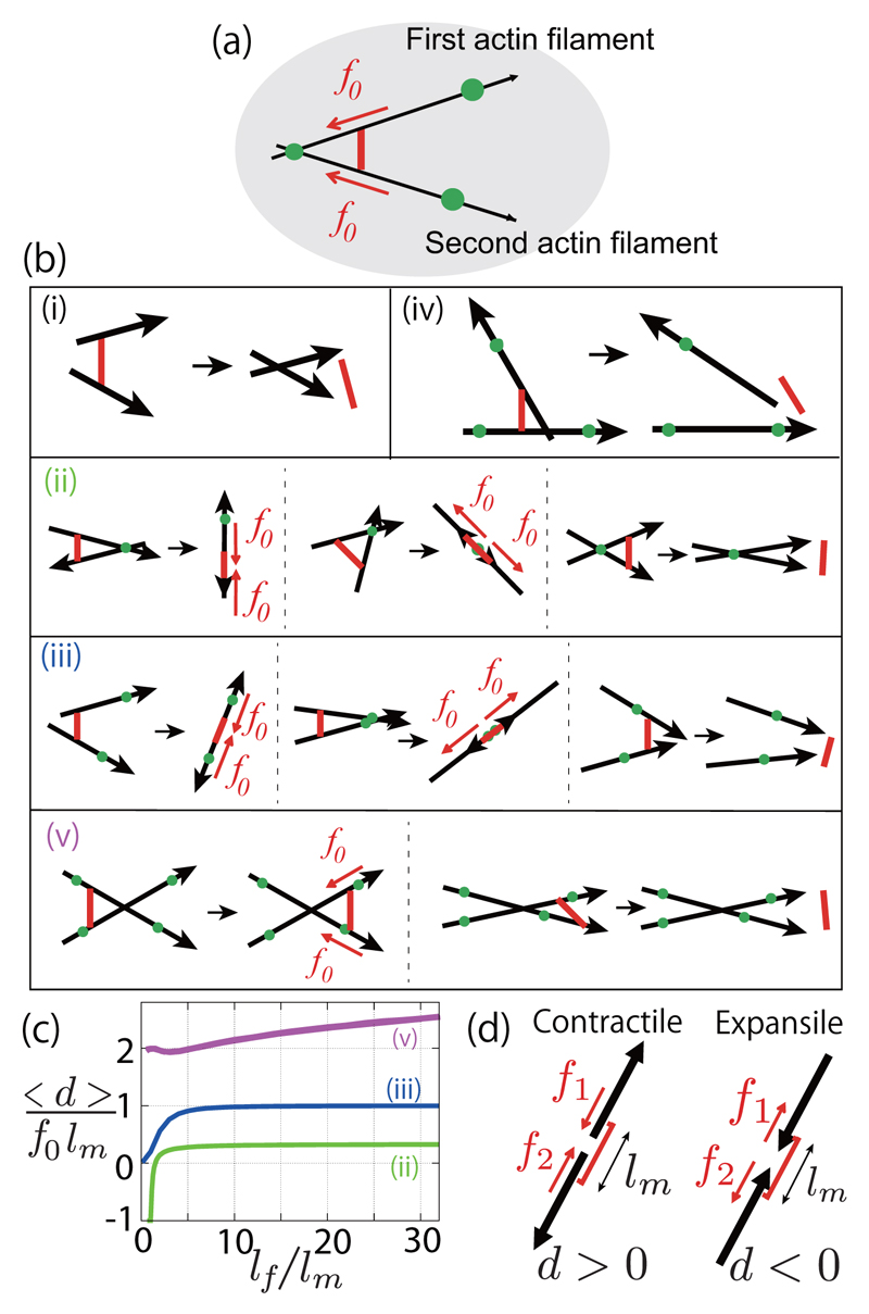
We start by discussing the dynamics of configurations involving one motor attached to two filaments [Fig. 2(a)]. The two filaments can be connected to a cross-linker, itself connected to the external network, here considered to be fixed in space. Depending on the positions of the cross-linkers, the two filaments can be completely free [Fig. 2(b)(i)], cross-linked to each other [Fig. 2(b)(ii)], or to the external network [Fig. 2(b)(iii)-(v)]. By averaging over possible initial configurations [30], we evaluate whether motors form on average positive or negative force dipoles at steady state [Fig. 2(c)]. The motor force dipole is d = (lm/2)n12·(f1 − f2),with lm being the length of the motor, n12 the unit vector giving the motor orientation, and f1 and f2 are the forces exerted by the motor ends on the filaments [see Fig. 2(d) and Supplemental Material [30]].
Fig. 2.
Contractile and expansile configurations for one motor and two filaments. (a) Two filaments are attached by fixed cross-linkers to the external network. (b) Possible initial configurations for one motor, two filaments, and one or several cross-linkers, and final configurations. (c) Average strength of the contractile force dipole generated by the molecular motor 〈d〉 in the final configurations (ii), (iii), (v) where the motor does not detach, as a function of the filament length lf. (d) Contractile (force dipole d > 0) and expansile (d < 0) configurations.
In cases shown in Figs. 2(b)(i) and 2(b)(iv), filaments are moved relative to each other until the motor detaches, so that a motor-induced force dipole acts on a transient time τ, which can be neglected in the quasistatic limit τ ≪ τc [Fig. 2(b)]. In the cases shown in Figs. 2(b)(ii), 2(b)(iii), and 2(b)(v), filaments relax to a steady configuration where the motor exerts a constant force dipole, always positive on average in the cases shown in Figs. 2(c)(iii) and 2(c)(v). In the case shown in Fig. 2(c)(v), f1 and f2 include the forces exerted by the motor themselves and by geometrical constraints [30]. As shown in Ref. [9], the bias towards contractile states arises from instabilities of expansile configurations [30]. The average force dipole 〈d〉 vanishes for pointlike motors, lm → 0 [14].
Numerical simulations of networks with turnover
We next numerically simulated a network of Nf filaments, Nm motor rods, and Nc passive cross-linkers in a square box of width W with periodic boundaries (Fig. 1). The frame of the box is not allowed to deform. The geometrical constraints g are enforced by stiff linear springs. Initial conditions are obtained by randomly positioning filaments. Turnover is introduced by stochastically removing cross-linkers, motors, and filaments from the network with rates 1/τc, 1/τm and 1/τf. For simplicity, turnover rates of cross-linkers are taken here independent of the forces they sustain. Note that the load dependency of cross-linking has been shown to influence network clustering [13]. Filaments, motors, and passive cross-linkers are added in random positions in the network with on rates , , and .
We evaluate the components of the stress tensor σij (i, j = x or y) acting on the boundary of the box [Fig. 1(a)]. The total stress is given by , with obtained by summing forces acting within the filaments and from forces acting within motor rods crossing the boundary of the box (Fig. 1). In a linear elastic or viscous material, in the absence of large-scale deformation and where 〈·〉 denotes averaging over positions in the box [30]. In a nonlinearly elastic material however, [30]. At steady state, the average stress acting within the motors is given by (see Ref. [31] and the Supplemental Material [30])
| (2) |
where n, d and c denote the orientation, the motor-induced force dipole strength, and the concentration of bound motors. When the dipoles are isotropically oriented, , with σm = c〈d〉/2.
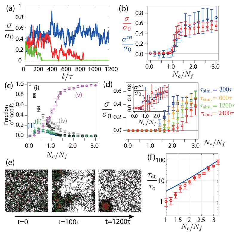
We first performed simulations without a turnover of filaments. We focus on the isotropic component of the stress σ ≡ (σxx + σyy)/2. Without cross-linker turnover, the system reaches a stationary state where the stress σ fluctuates around a finite positive value [Fig. 3(a)]. For a small number of cross-linkers (Nc → 0), no stress is generated, σ = 0, as motors are taken here to be identical. For nonidentical motors, a small isotropic stress can also be generated in the absence of cross-linkers [30]. Above a critical value of the number of cross-linkers , a transition occurs and a positive contractile stress appears in the system [Fig. 3(b)]. When , filaments aggregate in clusters and hence σ ∼ 0, suggesting that the transition is associated with the network connectivity (see movies M1 and M2 in the Supplemental Material [30]). Such a transition to contractility as a function of the number of cross-linkers has been reported in in vitro reconstituted networks [10, 34], as well as network clustering [35]. The average stress within the motors σm is plotted in Fig. 3(b). The stress σm is larger than the total stress for a large number of cross-linker Nc > Nf, implying that the filament network is under compression (σf < 0). For large Nc, the configurations shown in Fig. 3(c)(v) dominate in the network. The saturating value of σm/σ0 ∼ 0.6 is, nevertheless, smaller than the average force dipole obtained by averaging all possible filament orientations 〈d〉/(2f0lm) ∼ 1.0 [Fig. 2(c)]; this is because some configurations do not relax to equilibrium on the time scale of myosin turnover.
Fig. 3.
Stress in a network of motors and filaments, with and without cross-linker turnover. (a) Time evolution of the normalized stress σ/σ0 for τc−1 = 0, Nc = 1.2Nf (blue), τc = 100τ, Nc = 1.6 Nf (red) and τc = 100τ, Nc = 1.2Nf (green) (σ0 = f0lmNm/W2). (b) Steady-state isotropic stress σ (circles) and motor stress σm (diamonds) as a function of the cross-linkers number Nc for τc−1 = 0. (c) Fraction of different configurations in Figs. 2(i)-2(v) at steady state as a function of the cross-linker number Nc for τc−1 = 0. (d) Isotropic stress σ as a function of the cross-linker number Nc, for a finite cross-linker lifetime τc = 100τ, and for several simulation times (τsim. = 300, 600, 1200 and 2400τ). Stress within the motors σm is shown in the inset for τsim. = 300 and 2400τ. (e) Snapshots of a simulated network with cross-linker turnover (Nc = 1.2Nf, τc = 100τ). (f) Stress decay time τst as a function of the cross-linker number Nc with cross-linker turnover (τc = 100τ). Solid line, theoretical prediction (see the main text). Other parameters are Nf = 1000, Nm = 100, τf−1 = 0, , lf = 2lm, W = 10lm,τm = 100τ, and .
When cross-linkers are allowed to turn over, the average stress first reaches a positive value before decaying to zero [Fig. 3(a), red and green curves], even though the stress within the motors σm is still nonzero [Fig. 3(d)]. The decay of the stress correlates with the collapse of the network in an isolated cluster, where filaments accumulate [see Fig. 3(e) and movie M3 in the Supplemental Material [30]]. To evaluate the decay time scale τst, we fitted an exponentially decreasing function σ(t) = A exp(−t/τst) to the simulation results. τst increases exponentially with Nc for large Nc [Fig. 3(f)]. The time scale τst t corresponds to the relaxation Maxwell time on which the network becomes fluid due to turnover of passive cross-linkers enabling network rearrangements. With this picture, we estimate
| (3) |
With , which accounts for τst for large values of Nc/Nf [Fig. 3(f)]. To obtain Eq. (3), we assume that filaments with at least one cross-linker are fixed, and only filaments with no cross-linker attachment can rearrange. We then compute the first passage time at which a filament is free from cross-linkers, starting from a configuration where the filament is attached with only one cross-linker [30]. Thus, networks with cross-linker turnover can sustain only a transient stress, on a time scale that increases with cross-linker concentration [36].
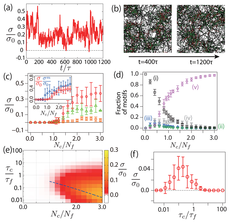
We now turn to simulations where both filaments and cross-linkers turn over. Remarkably, the network then evolves towards a steady state with a nonzero positive stress [Figs. 4a and 4b]. Introducing filament turnover prevents the clustering mechanism observed with cross-linker turnover (see movies M4 and M5 in the Supplemental Material [30]). As in the previous case, a transition from a noncontractile to a contractile network appears when the number of cross-linkers Nc is increased [Fig. 4(c)]. The stress σ deviates again from the average stress within the motors σm [Fig. 4(c), inset]. The dependency of the fraction of configurations as a function of Nc is qualitatively similar to the case without filament turnover [Fig. 4(d)].
Fig. 4.
Stress in a network with filament turnover. (a) Time evolution of the stress in a network with cross-linkers and filament turnover for τf = 100τ, τc = 100τ and Nc/Nf = 1.6. (b) Snapshots of the network evolution corresponding to (a). (c) Steady-state stress σ as a function of the number of cross-linkers for τc = τf = 100τ (circles), τc = τf = 10τ (triangles) and τc = τf = τ (squares). (Inset) Steady-state stress σ (circles) and motor stress σm (diamonds) for τc = τf = 100τ. (d) Fraction of different configurations (i)–(v) at steady state, as a function of Nc (τc = 100τ, τf = 100τ). (e) Heat map for contractile stress σ as a function of Nc and τc/τf (τc = τ). The broken line indicates τf = τst. (f) Stress as a function of the ratio of filament and cross-linker turnover rate (τc = τ, Nc = 1.6Nf). Other parameters are as in Fig. 3, except that and .
We then varied the cross-linker number Nc and filament turnover time scale τf to obtain a phase diagram of stress generation [Fig. 4(e)]. The stress reaches a maximum for intermediate values of the filament turnover time scale τf ∼ τst [broken line in Fig. 4(e), and Fig. 4(f)]: for slow filament turnover τf ≫ τst, the network collapses in clusters due to cross-linker turnover, while for fast filament turnover τf ≪ τst, filaments are removed before motors reach a configuration where they can exert a force dipole in the network.
An optimal ratio of filament and cross-linker turnover times is therefore needed for contractile stress generation. Interestingly, experimentally measured values of turnover of actin and cross-linker times in the cell cortex, τf ∼ 15–45 s and τc ∼ 7–14 s [1] yield a ratio of turnover time scale τc/τf ∼ 0.15–1, which lies in the region of optimum stress generation near the transition cross-linker density in Fig. 4(f). It will be interesting to investigate stress generation in in vitro experiments where cross-linkers and filaments are allowed to turn over [37]. Future work will also have to investigate the role of motor multivalency, and cross-linker and motor angular elasticity in stress generation.
Supplementary Material
Acknowledgments
We thank Matthew Smith for the helpful discussions. This work was supported partly by the JSPS Institutional Program for Young Researcher Overseas Visits (T. H.), the Postdoctoral Research Fellowship of the Alexander von Humboldt foundation (T. H.), the JSPS Core-to-Core Program (T. H.), the Max Planck Gesellschaft (G. S.), and the Francis Crick Institute which receives its core funding from Cancer Research UK, the UK Medical Research Council, and the Wellcome Trust (G. S).
Footnotes
PACS numbers: 87.16.Ln, 87.16.Ka, 87.16.Nn, 87.16.A-
References
- [1].Salbreux G, Charras G, Paluch E. Actin cortex mechanics and cellular morphogenesis. Trends Cell Biol. 2012;22:536. doi: 10.1016/j.tcb.2012.07.001. [DOI] [PubMed] [Google Scholar]
- [2].Joanny J-F, Prost J. Active gels as a description of the actin-myosin cytoskeleton. HFSP J. 2009;3:94. doi: 10.2976/1.3054712. [DOI] [PMC free article] [PubMed] [Google Scholar]
- [3].Mayer M, Depken M, Bois JS, Jülicher F, Grill SW. Anisotropies in cortical tension reveal the physical basis of polarizing cortical flows. Nature (London) 2010;467:617. doi: 10.1038/nature09376. [DOI] [PubMed] [Google Scholar]
- [4].Behrndt M, Salbreux G, Campinho P, Hauschild R, Oswald F, Roensch J, Grill SW, Heisenberg C-P. Forces driving epithelial spreading in zebrafish gastrulation. Science. 2012;338:257. doi: 10.1126/science.1224143. [DOI] [PubMed] [Google Scholar]
- [5].Murrell M, Gardel ML. Actomyosin sliding is attenuated in contractile biomimetic cortices. Mol Biol Cell. 2014;25:1845. doi: 10.1091/mbc.E13-08-0450. [DOI] [PMC free article] [PubMed] [Google Scholar]
- [6].Kruse K, Jülicher F. Actively Contracting Bundles of Polar Filaments. Phys Rev Lett. 2000;85:1778. doi: 10.1103/PhysRevLett.85.1778. [DOI] [PubMed] [Google Scholar]
- [7].Liverpool TB, Marchetti MC, Joanny J-F, Prost J. Mechanical response of active gels. Europhys Lett. 2009;85:18007. [Google Scholar]
- [8].e Silva MS, Depken M, Stuhrmann B, Korsten M, MacKintosh FC, Koenderink GH. Active multistage coarsening of actin networks driven by myosin motors. Proc Natl Acad Sci USA. 2011;108:9408. doi: 10.1073/pnas.1016616108. [DOI] [PMC free article] [PubMed] [Google Scholar]
- [9].Dasanayake NL, Michalski PJ, Carlsson AE. General Mechanism of Actomyosin Contractility. Phys Rev Lett. 2011;107:118101. doi: 10.1103/PhysRevLett.107.118101. [DOI] [PMC free article] [PubMed] [Google Scholar]
- [10].Köhler S, Bausch AR. Contraction mechanisms in composite active actin networks. PLoS One. 2012;7:e39869. doi: 10.1371/journal.pone.0039869. [DOI] [PMC free article] [PubMed] [Google Scholar]
- [11].Lenz M, Gardel ML, Dinner AR. Requirements for contractility in disordered cytoskeletal bundles. New J Phys. 2012;14:033037. doi: 10.1088/1367-2630/14/3/033037. [DOI] [PMC free article] [PubMed] [Google Scholar]
- [12].Lenz M, Thoresen T, Gardel ML, Dinner AR. Contractile Units in Disordered Actomyosin Bundles Arise from F-Actin Buckling. Phys Rev Lett. 2012;108:238107. doi: 10.1103/PhysRevLett.108.238107. [DOI] [PMC free article] [PubMed] [Google Scholar]
- [13].Alvarado J, Sheinman M, Sharma A, MacKintosh FC, Koenderink GH. Molecular motors robustly drive active gels to a critically connected state. Nat Phys. 2013;9:591. [Google Scholar]
- [14].Lenz M. Geometrical Origins of Contractility in Disordered Actomyosin Networks. Phys Rev X. 2014;4:041002. [Google Scholar]
- [15].Oelz DB, Rubinstein BY, Mogilner A. A combination of actin treadmilling and cross-linking drives contraction of random actomyosin arrays. Biophys J. 2015;109:1818. doi: 10.1016/j.bpj.2015.09.013. [DOI] [PMC free article] [PubMed] [Google Scholar]
- [16].Guha M, Zhou M, Wang Y-L. Cortical actin turnover during cytokinesis requires myosin II. Curr Biol. 2005;15:732. doi: 10.1016/j.cub.2005.03.042. [DOI] [PubMed] [Google Scholar]
- [17].Tinevez J-Y, Schulze U, Salbreux G, Roensch J, Joanny J-F, Paluch E. Role of cortical tension in bleb growth. Proc Natl Acad Sci USA. 2009;106:18581. doi: 10.1073/pnas.0903353106. [DOI] [PMC free article] [PubMed] [Google Scholar]
- [18].Tawada K, Sekimoto K. A physical model of ATPinduced actin-myosin movement in vitro. Biophys J. 1991;59:343. doi: 10.1016/S0006-3495(91)82228-7. [DOI] [PMC free article] [PubMed] [Google Scholar]
- [19].Imafuku Y, Emoto Y, Tawada K. A protein friction model of the actin sliding movement generated by myosin in mixtures of MgATP and MgGTP in vitro. J Theor Biol. 1999;199:359. doi: 10.1006/jtbi.1999.0963. [DOI] [PubMed] [Google Scholar]
- [20].Jülicher F, Prost J. Cooperative Molecular Motors. Phys Rev Lett. 1995;75:2618. doi: 10.1103/PhysRevLett.75.2618. [DOI] [PubMed] [Google Scholar]
- [21].Morone N, Fujiwara T, Murase K, Kasai RS, Ike H, Yuasa S, Usukura J, Kusumi A. Three-dimensional reconstruction of the membrane skeleton at the plasma membrane interface by electron tomography. J Cell Biol. 2006;174:851. doi: 10.1083/jcb.200606007. [DOI] [PMC free article] [PubMed] [Google Scholar]
- [22].Charras GT, Hu C-K, Coughlin M, Mitchison TJ. Reassembly of contractile actin cortex in cell blebs. J Cell Biol. 2006;175:477. doi: 10.1083/jcb.200602085. [DOI] [PMC free article] [PubMed] [Google Scholar]
- [23].Ott A, Magnasco M, Simon A, Libchaber A. Measurement of the persistence length of polymerized actin using fluorescence microscopy. Phys Rev E. 1993;48:R1642. doi: 10.1103/physreve.48.r1642. [DOI] [PubMed] [Google Scholar]
- [24].Ishikawa R, Sakamoto T, Ando T, Higashi-Fujime S, Kohama K. Polarized actin bundles formed by human fascin-1: Their sliding and disassembly on myosin II and myosin V in vitro. J Neurochem. 2003;87:676. doi: 10.1046/j.1471-4159.2003.02058.x. [DOI] [PubMed] [Google Scholar]
- [25].Kubalek EW, Uyeda TQ, Spudich JA. A dictyostelium myosin II lacking a proximal 58-kDa portion of the tail is functional in vitro and in vivo. Mol Biol Cell. 1992;3:1455. doi: 10.1091/mbc.3.12.1455. [DOI] [PMC free article] [PubMed] [Google Scholar]
- [26].Batchelor GK. Slender-body theory for particles of arbitrary cross-section in Stokes flow. J Fluid Mech. 1970;44:419. [Google Scholar]
- [27].Richter D, Binder K, Ewen B, Stuehn B. Screening of hydrodynamic interactions in dense polymer solutions: A phenomenological theory and neutron-scattering investigations. J Phys Chem. 1984;88:6618. [Google Scholar]
- [28].Mukhina S, Wang Y-L, Murata-Hori M. Alphaactinin is required for tightly regulated remodeling of the actin cortical network during cytokinesis. Dev Cell. 2007;13:554. doi: 10.1016/j.devcel.2007.08.003. [DOI] [PMC free article] [PubMed] [Google Scholar]
- [29].Reichl EM, Ren Y, Morphew MK, Delannoy M, Effler JC, Girard KD, Divi S, Iglesias PA, Kuo SC, Robinson DN. Interactions between myosin and actin crosslinkers control cytokinesis contractility dynamics and mechanics. Curr Biol. 2008;18:471. doi: 10.1016/j.cub.2008.02.056. [DOI] [PMC free article] [PubMed] [Google Scholar]
- [30].See Supplemental Material, which includes Refs. [9, 11, 31–33], for details of derivations and additional simulation results.
- [31].Simha RA, Ramaswamy S. Hydrodynamic Fluctuations and Instabilities in Ordered Suspensions of Self-Propelled Particles. Phys Rev Lett. 2002;89:058101. doi: 10.1103/PhysRevLett.89.058101. [DOI] [PubMed] [Google Scholar]
- [32].Gardiner CW. Stochastic Methods. Springer-Verlag; Berlin: 1985. [Google Scholar]
- [33].Pury PA, Cáceres MO. Mean first-passage and residence times of random walks on asymmetric disordered chains. J Phys A. 2003;36:2695. [Google Scholar]
- [34].Bendix PM, Koenderink GH, Cuvelier D, Dogic Z, Koeleman BN, Brieher WM, Field CM, Mahadevan L, Weitz DA. A quantitative analysis of contractility in active cytoskeletal protein networks. Biophys J. 2008;94:3126. doi: 10.1529/biophysj.107.117960. [DOI] [PMC free article] [PubMed] [Google Scholar]
- [35].Köhler S, Schaller V, Bausch AR. Structure formation in active networks. Nat Mater. 2011;10:462. doi: 10.1038/nmat3009. [DOI] [PubMed] [Google Scholar]
- [36].Jung W, Murrell MP, Kim T. F-actin cross-linking enhances the stability of force generation in disordered actomyosin networks. Comput Part Mech. 2015;2:317. [Google Scholar]
- [37].Shah EA, Keren K. Symmetry breaking in reconstituted actin cortices. eLife. 2014;3:e01433. doi: 10.7554/eLife.01433. [DOI] [PMC free article] [PubMed] [Google Scholar]
Associated Data
This section collects any data citations, data availability statements, or supplementary materials included in this article.


