Abstract
Endovascular intervention using traditional neurovascular stents and densely braided flow diverters (FDs) have become the preferred treatment strategies for traditionally challenging intracranial aneurysms (IAs). Modeling stent and FD deployment in patient-specific aneurysms and its flow modification results prior to the actual intervention can potentially predict the patient outcome and treatment optimization. We present a clinically focused, streamlined virtual stenting workflow that efficiently simulates stent and FD treatment in patient-specific aneurysms based on expanding a simplex mesh structure. The simplex mesh is generated using an innovative vessel-specific initialization technique, which uses the patient’s parent artery diameter to identify the initial position of the simplex mesh inside the artery. A novel adaptive expansion algorithm enables the acceleration of deployment process by adjusting the expansion forces based on the distance of the simplex mesh from the parent vessel. The virtual stenting workflow was tested by modeling the treatment of two patient-specific aneurysms using the Enterprise stent and the Pipeline Embolization Device (commercial FD). Both devices were deployed in the aneurysm models in a few seconds. Computational fluid dynamics analyses of pre- and post-treatment aneurysmal hemodynamics show flow reduction in the aneurysmal sac in treated aneurysms, with the FD diverting more flow than the Enterprise stent. The test results show that this workflow can rapidly simulate clinical deployment of stents and FDs, hence paving the way for its future clinical implementation.
Keywords: Cerebral aneurysm, endovascular device, Pipeline Embolization Device, Enterprise stent, simplex mesh, flow diverter
Introduction
Endovascular intervention by coil embolization is currently the prevalent treatment modality of intracranial aneurysms (IAs) surpassing the traditional open-skull surgery. However, in giant, wide-necked and fusiform aneurysms coil-mass effect and herniation prevent the use of coils alone during the intervention. For such aneurysms, neurovascular stents are usually used in conjunction with coils (Biondi et al. 2007), where stents are deployed across the aneurysm orifice in the parent vessel to prevent coil herniation, while coils induce embolization inside the aneurysm. Furthermore, a radically different concept for treating these traditionally difficult aneurysms is flow diversion using a densely braided self-expandable stent known as flow diverter (FD) (Byrne et al. 2010). One or more FDs are deployed across the aneurysm orifice to divert blood flow away from the aneurysm to induce blood stasis and subsequent thrombotic occlusion of the aneurysm as well as the reconstruction of the parent vessel (Lanzino et al. 1999). Despite increasing success of these endovascular intervention strategies, post-treatment complications such as recanalization following stent-assisted coiling (Biondi, et al. 2007, Piotin et al. 2010, Raymond et al. 2003) and failure to occlude as well as delayed subarachnoid hemorrhage following FD treatment have been reported (Byrne, et al. 2010, Siddiqui et al. 2012). Therefore it is crucial to gain a better understanding of the intervention and develop means to predict treatment outcome before the actual intervention.
Since both stents and FDs alters aneurysmal flow, treatment outcome is dependent on their hemodynamic modification, which in turn is highly dependent on the devices used, how they are deployed, as well as the aneurysm and the vessel geometry. Hemodynamic factors such as intra-aneurysmal flow velocity, inflow rate and wall shear stress are clinically shown to correlate with IA treatment outcomes (Mut et al. 2015, Kulcsar et al. 2012). To increase treatment success and minimize complications, it is highly desirable for neurointerventionalists to have the ability to simulate various intervention strategies in patient-specific computational models and predict the post-treatment aneurysmal flow dynamics a priori. Hence, there is a need for a virtual stenting method that can rapidly deploy stents and FDs in patient-specific aneurysms in silico, and aid neurointerventionalists to prospectively evaluate different intervention strategies during treatment planning.
The existing virtual stenting methods fall into 3 categories: (1) Direct placement methods, which simply bends a uniform stent tube to fit inside the parent vessel (Kim, et al. 2008, Fu et al. 2010, Tremmel et al. 2010), are not suitable for treatment planning due to grossly unrealistic stent or FD geometry and poor stent-wall apposition. (2) Finite element method based techniques (Ma et al. 2012, Ma et al. 2013, Ma et al. 2014, Xiang et al. 2014), which more realistically simulate the mechanical processes in the deployment procedure come at high computation costs that prohibit them from use in routine clinical treatment planning. (3) Simplified expansion methods use computationally efficient algorithms to expand a surrogate stent surface within the parent vessel (Appanaboyina, et al. 2009, Larrabide, et al. 2012) and are most promising as clinical planning tools. Among these, the simplified expansion methods offer the highest potential for future clinical implementation (Bernardini et al. 2011); however they encounter problems in complex patient-specific geometries. In the earliest expansion approach a cylindrical surface was geometrically inflated in the parent vessel, where the surface crossed the vessel wall in patient-specific geometries, thus requiring a negative force to bring it back to within the vessel (Appanaboyina et al. 2009). Larrabide et al. overcame this problem by expanding a simplex mesh structure instead of a geometrical surface, and incorporating simplified forces among the stent struts and between the stent struts and the parent vessel in their modeling (Larrabide et al. 2012). However, concerns have been raised on the lack of accuracy of this method in complex tortuous vessel geometries (Spranger et al. 2014). In these cases the differences due to the expansion of a simplex mesh instead of the actual stent struts are magnified. None of the existing virtual stenting methods have been adopted clinically.
To bring virtual stenting to the clinical practice, two hurdles have to be overcome: the algorithm should be able to handle complex, tortuous cerebral vessel geometry, and the workflow should be computationally efficient for prospective clinical application. To this end, we develop a virtual stenting algorithm that incorporates two novel features –vessel-specific initialization and adaptive expansion – and integrate it onto a virtual stenting workflow that aims at facilitating treatment planning of endovascular interventions. In this paper we present a technical description of the workflow and test the workflow retrospectively on two patient-specific IA cases.
Methods
The virtual stenting workflow is built on the concept of a simplex mesh, a generalized deformable structure that can expand depending on the relative position of its mesh points. The workflow consists of 3 operations on the simplex mesh (1) initialization, (2) expansion in the vessel, and (3) stent pattern mapping. The workflow was tested on two patient-specific aneurysm geometries, by deploying commercial stents and FDs on these geometries Computational fluid dynamic (CFD) analyses was then performed on these cases to obtain pre- and post-treatment hemodynamics.
Virtual Stenting Workflow
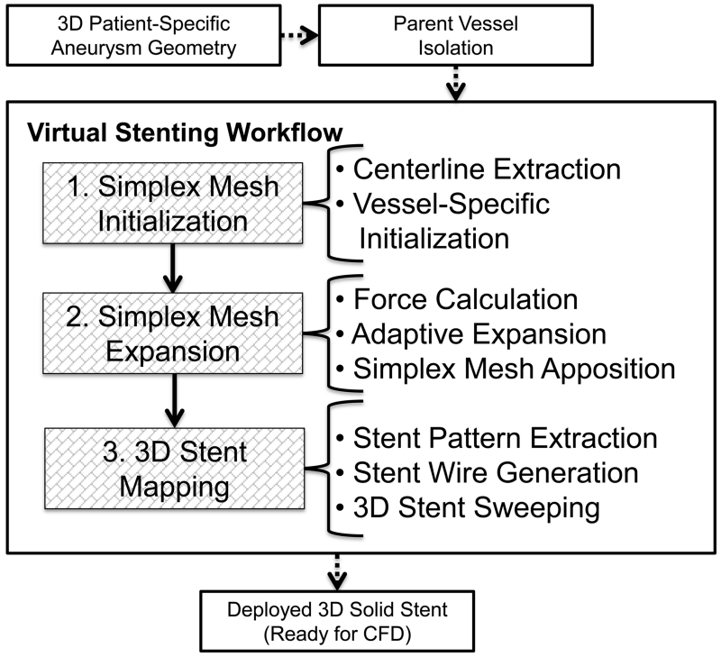
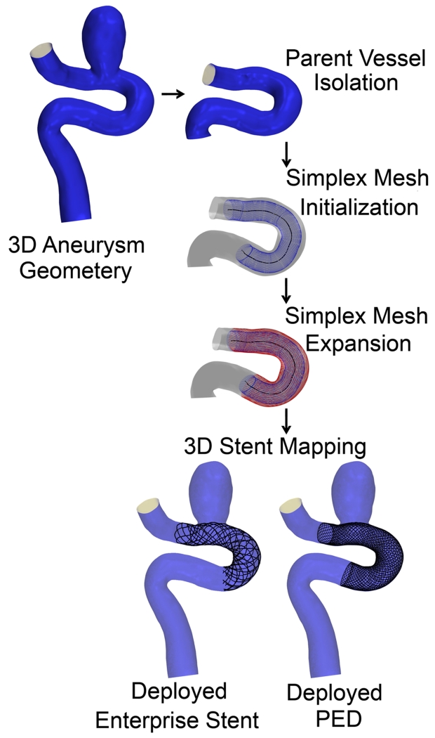
Before the workflow starts, the parent vessel is isolated from the aneurysm using Vascular Modeling Toolkit (vmtk), (Antiga et al. 2006). Then the workflow is applied to the parent vessel in three steps as shown in Figure 1. A simplex mesh is first generated using a novel vessel-specific initialization technique (Step 1). This simplex mesh is then expanded until it apposes to the vessel wall (Step 2) using a novel adaptive expansion algorithm. After the expansion stops, the stent or FD pattern is mapped on the deployed simplex mesh to obtain the stent or FD (Step 3).
Figure 1.
Virtual stenting workflow flowchart.
Step 1: Simplex Mesh Initialization
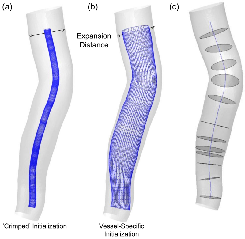
In the first step, a simplex mesh is generated in the parent vessel to represent the stent surface prior to its expansion. Traditionally, a crimped mesh (a skinny mesh) with a small uniform diameter is placed along the centerline of the parent vessel during initialization as shown in Figure 2(a). Although conceptually straightforward, starting with a crimped mesh is computationally expensive to expand the mesh from peri-centerline to the vessel wall (expansion is described in Step 2), since the vast majority of expansion iterations cover the free expansion of the simplex mesh that does not interact with the vessel until close to the wall. These iterations could be eliminated to save computation time.
Figure 2.
Two type of simplex mesh initializations: (a) The commonly used ‘crimped’ or small-radius initialization of simplex mesh and (b) vessel-specific initialization of simplex mesh. (c) Centerline and maximum inscribed sphere cross-sections in the vessel, used while placing the simplex mesh during initialization.
To this end, we introduce a novel approach to vessel-specific simplex mesh initialization in patient-specific aneurysm geometries to achieve improved efficiency. The idea is illustrated in Figure 2(b). Simplex mesh initialized using vessel-specific initialization skips the majority of expansion iterations inherent with the crimped simplex mesh initialization. As shown in Figure 2(c), first the maximum inscribed sphere diameter inside the parent vessel along its centerline is extracted. Then a series of circles at corresponding cross sections along the vessel centerline are placed. The circles are then connected to obtain the simplex mesh. This vessel specific initialization is computationally efficient, leaving the actual expansion to only a fraction of distance from the wall.
Step 2: Simplex Mesh Expansion
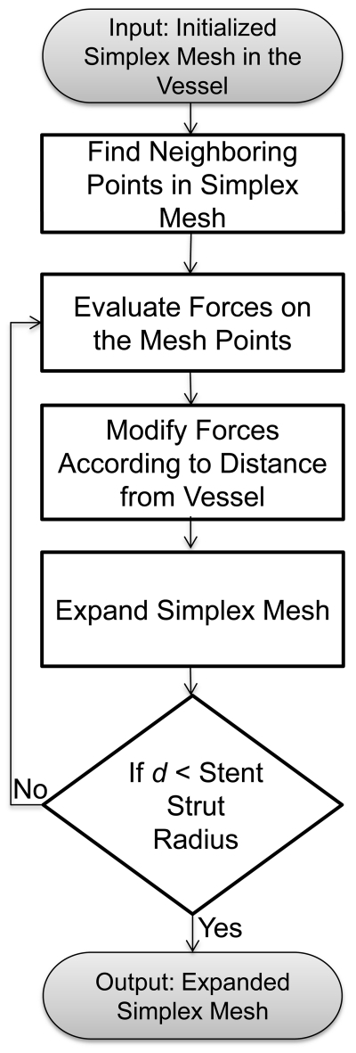
Next, the initialized simplex mesh is expanded based on the concept of a deformable simplex mesh structure (Delingette 1999). The flowchart of the algorithm is shown in Figure 3.
Figure 3.
Simplex mesh expansion algorithm.
The motion of the simplex mesh expansion is governed by a second-order partial differential equation (Larrabide, et al. 2012, Montagnat et al. 2005) :
where pi is the position of a simplex mesh point, fint and fext are internal and external forces, respectively. α and β are the weighting factors for internal and external forces. In each iteration, the imbalance between these forces drives the simplex mesh expansion. The first term on the left side represents acceleration of the simplex mesh, while the second term represents a damping force with γ being the damping coefficient. This equation is discretized as:
where t is the current iteration step, t – 1 is the previous iterations and pi (i = 1,2,3,…) is a simplex point. Both fint and fext are calculated on each simplex mesh point pi and varied according to the position of pi inside the parent vessel. The internal force fext on a simplex mesh point pi is calculated based on its position relative to the neighbors in simplex mesh structure, represented by angle force and length force. The external force fext depends on the location of pi inside parent vessel. The definitions of fint and fext have been previously defined (Larrabide, et al. 2012). To stabilize this discretized equation, values of the coefficients must be within certain ranges (Appanaboyina, et al. 2009) : 0 ≤α≤ 0.5, 0 ≤β≤ 1 and 0 ≤γ≤ 1. The values that we chose were α = β = 0.02 and γ = 0.5, which gave the most realistic expansion results for multiple test cases.
To eliminate the possibility of simplex mesh crossing the vessel wall during expansion and to further speedup the expansion, a response loop, adaptive expansion is embedded in the algorithm, in which forces (both external and internal) are modified in each iteration to adapt to the current location of the simplex mesh. First a coefficient φi is evaluated that keeps track of the distance between each simplex mesh point pi and the vessel wall (di):
where is the ratio of the distance in the current iteration (t) over the distance in the previous iteration (t – 1). The initial value of φi is equal to 1. As the mesh expands, φi decreases progressively. φi is embedded in the expansion algorithm in force term according to equation:
where and are total forces in two consecutive iterations.
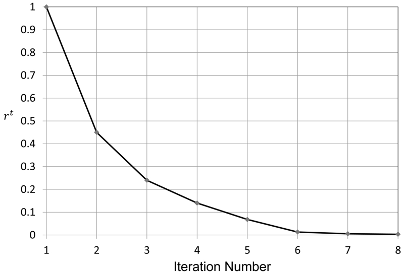
The introduction of φi in force terms maximizes the speed of the expansion. When the simplex mesh is far from the vessel wall, φi has a higher value, resulting in large expansion force which accelerates the expansion. During later iteration steps when the simplex mesh gets closer to the vessel wall, the value of φi decreases, resulting in smaller subsequent expansion forces giving slower acceleration at small distances. We define a ratio parameter at every simplex mesh point to illustrate the effect of adaptive expansion. The ratio parameter rt is defined as the distance of the simplex mesh from the vessel wall normalized by the initial distance d1:
The parameter rt is plotted against iteration number in Figure 4, which shows that the simplex mesh initially covers large distances and the expansion is fast. When the simplex mesh is close to the vessel wall, the expansion slows down. Progressively decreasing expansion forces eventually result in containment of the simplex mesh inside the parent vessel during its expansion.
Figure 4.
Normalized distance of the simplex mesh from vessel wall plotted against the iteration number.
Step 3: 3D Stent Mapping
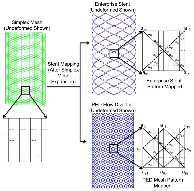
After the simplex mesh is deployed in the vessel, the specific stent is generated onto its surface in two steps: (1) mapping the stent pattern, which consists of wire curves; (2) sweeping the wire curves into 3D stent structures. In the first step, the stent vertex coordinates on the deployed simplex mesh are determined according to the stent pattern. Then the vertex coordinates are connected to form distinct wire curves. In the second step, these wires curves are swept into 3D strut structures to generate the 3D solid stent. For clarity, this process is illustrated in Figure 5 on an idealized, undeformed simplex mesh. In the patient-specific virtual stenting workflow, the stent mapping is performed on already deployed and distorted simplex mesh.
Figure 5.
Stent mapping pattern on the deployed simplex mesh, illustrated on an idealized cylinder. To illustrate the Enterprise stent model (top), Wire 1 (solid line in insert) is obtained from joining vertex coordinates a11, a22,…, a99, and Wire 2 (dashed line in insert) is obtained from joining vertex coordinates a19, a28,…, a91. Wire 1 and Wire 2 are repreated 8 times to obtain a total of 16 wires. For the PED pattern (bottom), Wire 1 and Wire 2 are obtained in the same manner and repeated 24 times to produce a total of 48 wires.
As examples, mapping patterns for one porous stent and one FD are coded: (1) the Enterprise Vascular Reconstruction Device, commonly referred to as the Enterprise stent (Codman Neurovascular, Raynham, MA), and (2) the Pipeline Embolization Device, commonly referred to as the PED (Covidien, Irvine, CA). Both devices are widely used clinically for IA treatment. The Enterprise stent is a porous laser-cut stent with a rectangular cross-section of 38.1 μm × 78.7 μm. It is modeled as overlaying 16 wires to obtain the required mapping pattern on the simplex mesh structure, as illustrated in Figure 5. The PED is a densely braided FD with 48 distinct circular wires of diameter 30 μm each. The PED is obtained by extracting 48 wires from the deployed simplex mesh according to the mapping pattern illustrated in Figure 5.
To obtain the 3D structure for stents, vertex coordinates are obtained by implementing mapping patterns on the deployed simplex mesh. These coordinates are then connected to obtain wire curves in an in-house python code based on the software Abaqus/Explicit 6.12 (SIMULIA, Providence, RI). Wire curves are then swept into 3D structures with appropriate geometry and dimensions matching the real devices. The Enterprise stent is swept using a rectangular cross-sectional base, while the PED is swept using a circular base at the cross-section in the CAD program Creo Parametric 2.0 (PTC, Needham, MA). 3D wire structures are placed inside the original untrimmed 3D aneurysm geometry and used for CFD analysis (the bottom box in Figure 1). The virtual stenting workflow codes were developed in MATLAB (R2013a, The Mathworks, Natick, MA).
Aneurysm Geometries
As test beds, two representative patient-specific 3D aneurysm models were chosen to apply the virtual stenting workflow. These include a sidewall aneurysm on the internal carotid artery (ICA) (Aneurysm I), and a wide-necked fusiform aneurysm on the basilar artery (BA) (Aneurysm II). An Enterprise stent and a PED were deployed on both aneurysm models and CFD was performed to evaluate hemodynamics.
CFD Modeling
CFD simulations were performed on Aneurysms I and II using STAR-CCM+ (CD-adapco, Melville, NY). The second-order finite volume solver was used to solve the flow governing Navier-Stokes equations under the conditions of steady-state, incompressible and laminar flow. The aneurysm wall was simplified as rigid and blood was treated as a Newtonian fluid with a density of 1056 kg/m3 and a viscosity of 0.0035 Pa-s. Inlet velocities were estimated based on location of each artery and set to be 0.35 m/s for Aneurysm I (ICA) and 0.29 m/s for Aneurysm II (BA). Flow-split outlet condition was specified at the outlets in both simulations. Inflow reduction inside the aneurysm dome was calculated at the neck plane.
Results
Virtual Stenting Results
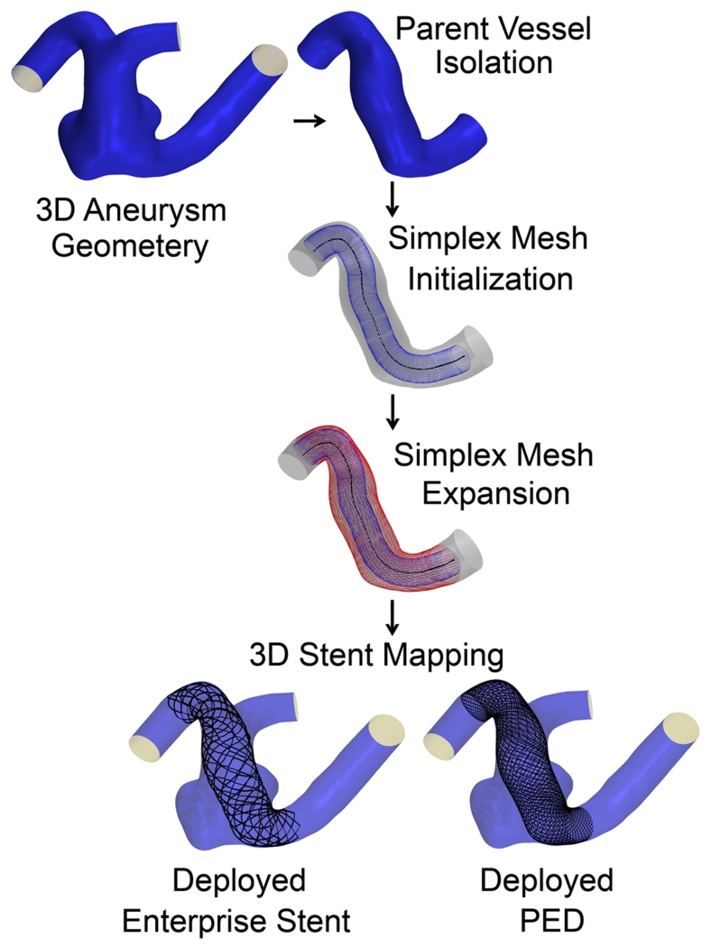
To illustrate the streamlined virtual stenting workflow, step-by-step results of the application of the workflow on Aneurysms I and II are illustrated in Figures 6 and 7. First a simplex mesh was initialized using vessel-specific initialization. Then the simplex mesh was expanded using the expansion algorithm. Finally the Enterprise stent and the PED patterns on the simplex mesh were mapped, and the wires were swept into 3D structures to obtain the final deployed Enterprise stent and PED geometries.
Figure 6.
Step-by-step results for the application of the virtual stenting workflow on Aneurysm I.
Figure 7.
Step-by-step results for the application of the virtual stenting workflow on Aneurysm II.
Table 1 documents the time required for each step and the overall time of running the virtual stenting workflow. Aneurysm II required 37% longer time than Aneurysm I for simplex mesh expansion, because its fusiform geometry required a longer stent to cover the aneurysmal region, thereby more simplex mesh nodes to expand. Furthermore, compared with the Enterprise stent PED required 50% and 80% longer time to map in Aneurysm I and II, respectively. This was because the PED has 48 wires while the Enterprise stent has 16 wires only.
Table 1.
Time performance during each step of virtual stenting workflow on Aneurysms I and II.
| Aneurysm I | Aneurysm II | |||
|---|---|---|---|---|
| Initialization | 0.32 sec | 0.33 sec | ||
| Expansion | 13.2 sec | 18.1 sec | ||
| Stent Mapping | Enterprise Stent | PED | Enterprise Stent | PED |
| 0.61 sec | 0.92 sec | 0.52 sec | 0.94 sec | |
| Total Time | 14.13 sec | 14.44 sec | 18.95 sec | 19.37 sec |
CFD Results
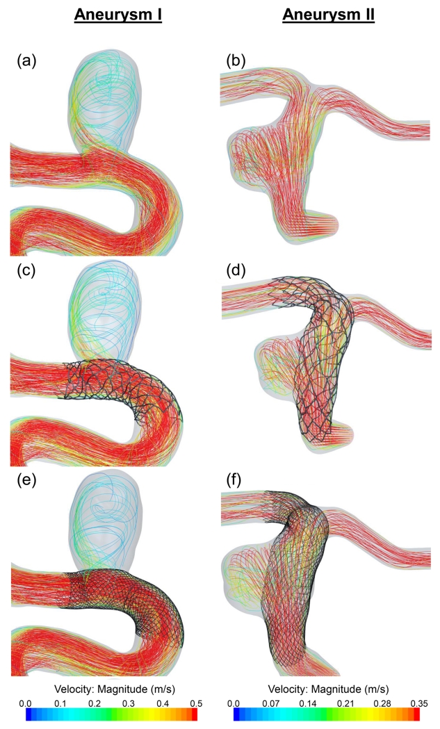
Figure 8 shows flow streamlines results for untreated aneurysms (a, b), after treatment by the Enterprise stent (c, d) and the PED (e, f). Both Aneurysms I and II show reduced streamlines into the aneurysmal sac after treatment; however, the PED diverted more flow away from the aneurysm than the Enterprise stent. Before treatment, Aneurysm I was subjected to jet impingement at the distal wall of the neck region. This jet was diminished by the PED as well as by the Enterprise stent. The inflow rate in Aneurysm I was reduced by 21% due to the PED and 12% due to the Enterprise stent. For Aneurysm II, the inflow rate was reduced by 19% and 11% respectively.
Figure 8.
CFD results showing flow streamlines on Aneurysms I and II. (a), (b): Untreated aneurysms. (c), (d): After implanting an Enterprise stent. (e), (f): After implanting a PED.
Discussion
Currently a number of virtual intervention tools are available (Ma, et al. 2012, Appanaboyina, et al. 2009, Larrabide, et al. 2012, Spranger, et al. 2014, Cebral et al. 2005, Damiano et al. 2015) but none has been adopted by the clinicians, largely because these tools lack the computational efficiency and an easy streamlined structure to be translated to the clinical settings, or are not accurate enough to represent the actual deployed stents in patient-specific aneurysms. The current study addresses this problem by developing a virtual stenting tool for neurovascular stents and flow diverters aimed at potential clinical use.
The virtual stenting algorithm in this study advances existing simplified expansion methods by solving the problem of deployment in tortuous vessels and striking a balance between efficiency and accuracy. Vessel-specific initialization uses patient-specific artery lumen diameter, and generates a patient vessel-specific simplex mesh for the aneurysm geometry. Vessel-specific initialization enables the expansion algorithm to tackle complex tortuous geometries. Furthermore, the expansion algorithm uses adaptive expansion to expand the simplex mesh, which incorporates the relative location of the simplex mesh inside the parent vessel during expansion. The forces are modified in each iteration step to regulate the acceleration of the simplex mesh during expansion. Adaptive expansion also decreases the computation time by reducing the number of steps required for expansion. Moreover, a workflow is developed to integrate the expansion into a computational framework and streamline the entire stent modeling procedure. This positions the workflow for easy clinical implementation.
Although the workflow is developed primarily for application in IAs, it can be applied to other similar medical applications. In abdominal aortic aneurysm, the workflow can be used to deploy stent grafts by mapping the graft pattern on the simplex mesh. But this workflow cannot be used in modeling traditional stents, where the purpose is to expand the arteries by using stents, since the blood vessel is assumed rigid in this workflow.
A limitation of the current study is that material properties and deployment of actual stents are not incorporated in the modeling. Instead, a generic simplex mesh is used, which may result in unrealistic stent deformation and eventual inaccurate stent wire positioning, especially in tortuous cerebral arteries. Also, the mapping of Enterprise stent pattern on the simplex mesh is an approximation of the actual Enterprise stent structure. To evaluate the effects of these limitations, detailed validation of the virtual stenting workflow will be performed. Although the efficiency of the virtual stenting workflow has been quantified in the current study, future studies will aim at the quantification of its accuracy. For post-treatment hemodynamic validation, results will be compared with in vitro experimental study using particle image velocimetry in future studies. This validation will assess the accuracy of the virtual stenting workflow and its potential usefulness as a tool in clinical treatment planning.
Conclusion
A streamlined virtual stenting workflow for in silico neurovascular stent deployment is developed in this study. Novel features like vessel-specific initialization of simplex mesh and adaptive expansion empowers the workflow with a high-efficiency reliable performance in complex patient-specific cerebral arterial geometry, as indicated by its test on two patient-specific IA cases. This shows that the workflow is promising for clinical integration and facilitating treatment planning.
Acknowledgments
This work was supported by the National Institutes of Health (1R01 NS 091075-01) and National Science Foundation of China (Grants 81220108007 and 81171079). The authors would like to acknowledge Vincent Tutino for assistance in preparation of figures, and Robert Damiano and Rahul Sanal for technical assistance.
References
- Biondi A, Janardhan V, Katz JM, Salvaggio K, Riina HA, Gobin YP. Neuroform stent-assisted coil embolization of wide-neck intracranial aneurysms: Strategies in stent deployment and midterm follow-up. Neurosurgery. 2007;61:460–469. doi: 10.1227/01.NEU.0000290890.62201.A9. [DOI] [PubMed] [Google Scholar]
- Byrne JV, Beltechi R, Yarnold JA, Birks J, Kamran M. Early experience in the treatment of intra-cranial aneurysms by endovascular flow diversion: A multicentre prospective study. PLoS ONE. 2010;5:e12492. doi: 10.1371/journal.pone.0012492. [DOI] [PMC free article] [PubMed] [Google Scholar]
- Lanzino G, Wakhloo AK, Fessler RD, Hartney ML, Guterman LR, Hopkins LN. Efficacy and current limitations of intravascular stents for intracranial internal carotid, vertebral, and basilar artery aneurysms. Journal of Neurosurgery. 1999;91:538–546. doi: 10.3171/jns.1999.91.4.0538. [DOI] [PubMed] [Google Scholar]
- Piotin M, Blanc R, Spelle L, Mounayer C, Piantino R, Schmidt PJ, Moret J. Stent-assisted coiling of intracranial aneurysms clinical and angiographic results in 216 consecutive aneurysms. Stroke. 2010;41:110–115. doi: 10.1161/STROKEAHA.109.558114. [DOI] [PubMed] [Google Scholar]
- Raymond J, Guilbert F, Weill A, Georganos SA, Juravsky L, Lambert A, Lamoureux J, Chagnon M, Roy D. Long-Term Angiographic Recurrences After Selective Endovascular Treatment of Aneurysms With Detachable Coils. Stroke. 2003;34:1398–1403. doi: 10.1161/01.STR.0000073841.88563.E9. [DOI] [PubMed] [Google Scholar]
- Siddiqui AH, Abla AA, Kan P, Dumont TM, Jahshan S, Britz GW, Hopkins LN, Levy EI. Panacea or problem: flow diverters in the treatment of symptomatic large or giant fusiform vertebrobasilar aneurysms. Journal of Neurosurgery. 2012;116:1258–1266. doi: 10.3171/2012.2.JNS111942. [DOI] [PubMed] [Google Scholar]
- Mut F, Raschi M, Scrivano E, Bleise C, Chudyk J, Ceratto R, Lylyk P, Cebral JR. Association between hemodynamic conditions and occlusion times after flow diversion in cerebral aneurysms. Journal of Neurointerventional Surgery. 2015;7:286–290. doi: 10.1136/neurintsurg-2013-011080. [DOI] [PubMed] [Google Scholar]
- Kulcsar Z, Augsburger L, Reymond P, Pereira VM, Hirsch S, Mallik AS, Millar J, Wetzel SG, Wanke I, Rufenacht DA. Flow diversion treatment: intra-aneurismal blood flow velocity and WSS reduction are parameters to predict aneurysm thrombosis. Acta neurochirurgica. 2012;154:1827–1834. doi: 10.1007/s00701-012-1482-2. [DOI] [PubMed] [Google Scholar]
- Ma D, Dargush GF, Natarajan SK, Levy EI, Siddiqui AH, Meng H. Computer modeling of deployment and mechanical expansion of neurovascular flow diverter in patient-specific intracranial aneurysms. Journal of Biomechanics. 2012;45:2256–2263. doi: 10.1016/j.jbiomech.2012.06.013. [DOI] [PubMed] [Google Scholar]
- Ma D, Dumont TM, Kosukegawa H, Ohta M, Yang X, Siddiqui AH, Meng H. High Fidelity Virtual Stenting (HiFiVS) for Intracranial Aneurysm Flow Diversion: In Vitro and In Silico. Annals of Biomedical Engineering. 2013;41:2143–2156. doi: 10.1007/s10439-013-0808-4. [DOI] [PMC free article] [PubMed] [Google Scholar]
- Ma D, Xiang J, Choi H, Dumont TM, Natarajan SK, Siddiqui AH, Meng H. Enhanced Aneurysmal Flow Diversion Using a Dynamic Push-Pull Technique: An Experimental and Modeling Study. American Journal of Neuroradiology. 2014 doi: 10.3174/ajnr.A3933. [DOI] [PMC free article] [PubMed] [Google Scholar]
- Xiang J, Ma D, Snyder KV, Levy EI, Siddiqui AH, Meng H. Increasing flow diversion for cerebral aneurysm treatment using a single flow diverter. Neurosurgery. 2014 Sep;75:286–294. doi: 10.1227/NEU.0000000000000409. discussion 294. Epub 2014/05/29. [DOI] [PubMed] [Google Scholar]
- Bernardini A, Larrabide I, Morales HG, Pennati G, Petrini L, Cito S, Frangi AF. Influence of different computational approaches for stent deployment on cerebral aneurysm haemodynamics. Interface Focus. 2011;1:338–348. doi: 10.1098/rsfs.2011.0004. [DOI] [PMC free article] [PubMed] [Google Scholar]
- Appanaboyina S, Mut F, Lohner R, Putman C, Cebral J. Simulation of intracranial aneurysm stenting: Techniques and challenges. Computer Methods in Applied Mechanics and Engineering. 2009;198:3567–3582. [Google Scholar]
- Larrabide I, Kim M, Augsburger L, Villa-Uriol MC, Rufenacht D, Frangi AF. Fast virtual deployment of self-expandable stents: method and in vitro evaluation for intracranial aneurysmal stenting. Medical Image Analysis. 2012;16:721–730. doi: 10.1016/j.media.2010.04.009. [DOI] [PubMed] [Google Scholar]
- Spranger K, Ventikos Y. Which Spring is the Best? Comparison of Methods for Virtual Stenting. Biomedical Engineering, IEEE Transactions on. 2014;61:1998–2010. doi: 10.1109/TBME.2014.2311856. [DOI] [PubMed] [Google Scholar]
- Antiga L, Steinman D. VMTK: Vascular Modeling Toolkit. 2006 http://wwwvmtkorg.
- Delingette H. General Object Reconstruction Based on Simplex Meshes. International Journal of Computer Vision. 1999;32:111–146. [Google Scholar]
- Montagnat J, Delingette H. 4D deformable models with temporal constraints: application to 4D cardiac image segmentation. Medical Image Analysis. 2005;9:87–100. doi: 10.1016/j.media.2004.06.025. [DOI] [PubMed] [Google Scholar]
- Cebral JR, Lohner R. Efficient simulation of blood flow past complex endovascular devices using an adaptive embedding technique. Biomedical Engineering, IEEE Transactions on. 2005;24:468–476. doi: 10.1109/tmi.2005.844172. [DOI] [PubMed] [Google Scholar]
- Damiano RJ, Ma D, Xiang J, Siddiqui AH, Snyder KV, Meng H. Finite element modeling of endovascular coiling and flow diversion enables hemodynamic prediction of complex treatment strategies for intracranial aneurysm. Journal of Biomechanics. 2015 doi: 10.1016/j.jbiomech.2015.06.018. Epub 2015/07/15. [DOI] [PMC free article] [PubMed] [Google Scholar]


