Abstract
The blood flow pathway within a device, together with the biomaterial surfaces and status of the patient’s blood, are well-recognized factors in the development of thrombotic deposition and subsequent embolization. Blood flow patterns are of particular concern for devices such as blood pumps (i.e. ventricular assist devices, VADs) where shearing forces can be high, volumes are relatively large, and the flow fields can be complex. However, few studies have examined the effect of geometric irregularities on thrombus formation on clinically relevant opaque materials under flow. The objective of this study was to quantify human platelet deposition onto Ti6Al4V alloys, as well as positive and negative control surfaces, in the region of defined crevices (~50–150 µm in width) that might be encountered in many VADs or other cardiovascular devices. To achieve this, reconstituted fresh human blood with hemoglobin-depleted red blood cells (to achieve optical clarity while maintaining relevant rheology), long working optics, and a custom designed parallel plate flow chamber were employed. The results showed that the least amount of platelet deposition occurred in the largest crevice size examined, which was counterintuitive. The greatest levels of deposition occurred in the 90 µm and 53 µm crevices at the lower wall shear rate. The results suggest that while crevices may be unavoidable in device manufacturing, the crevice size might be tailored, depending on the flow conditions, to reduce the risk of thromboembolic events. Further, these data might be used to improve the accuracy of predictive models of thrombotic deposition in cardiovascular devices to help optimize the blood flow path and reduce device thrombogenicity.
Keywords: platelets, thrombosis, red blood cell ghosts, crevices, disturbed flow, microscopy
Introduction
Many blood-contacting medical devices remain associated with thrombotic and thromboembolic events that result in morbidity, mortality, and ultimately, a deterrent to the broader adoption of these technologies. [1–5] The blood flow pathway within a device, together with the biomaterial surface and status of the patient’s blood, is a well-recognized factor in the development of thrombotic deposition and subsequent embolization. [6] For instance, regions of flow separation, recirculation, and stagnation are known to lead to increased platelet deposition [7–10], and such flow conditions may occur near cardiac valves, arterial stents, and vascular grafts due to the disturbances introduced by the specific device architecture. [10–14] Blood flow patterns are of particular concern for devices such as blood pumps (i.e. ventricular assist devices, VADs) where shearing forces can be high, volumes are relatively large, and the flow fields can be complex.
Geometric irregularities, such as steps and crevices, within the flow path of continuous flow VADs serve as a nidus for thrombus formation. [7] Manufacturers make a great effort to reduce the presence of such features within their devices prior to implantation through precise machining and polishing. However, VADs are comprised of multiple parts that serve to create the blood contacting surfaces, so the introduction of internal steps and crevices is unavoidable at some level. There is also the possibility that surface imperfections can be introduced during the operation of some devices, for instance when a non-fixed VAD impeller collides with a housing surface and creates a scratch. [15]
Understanding how surface irregularities affect the development of thrombotic deposition on clinically relevant biomaterials would provide a useful tool for improving the blood flow path design and materials selection process for VADs and other blood-contacting medical devices. Such data could be used directly or in the development of mathematical models that seek to predict thrombotic deposition risk for a given biomaterial/geometry combination. To date, the use of flow visualization technologies such as particle image velocimetry (PIV) have become routine in blood pump design, as has the early evaluation of candidate biomaterials by acute blood contact under well-defined flow conditions or simple mixing. [6] There have been a limited number of in vitro studies that have examined real-time platelet deposition onto biomaterials in regions of disturbed flow. [16, 17] These reports did not evaluate geometries associated with device joints or surface imperfections and generally evaluated disturbances on a much larger scale. Further, these reports did not evaluate the opaque metallic materials used in the rotary blood pumps in common clinical use today. The objective of this report was to quantify human platelet deposition onto Ti6Al4V alloys, as well as positive and negative control surfaces, in the region of crevices (~50–150 µm in width) that might be encountered in many VADs or other cardiovascular devices. To achieve this, reconstituted fresh human blood with hemoglobin-depleted red blood cells (RBC ghosts, to achieve optical clarity while maintaining relevant rheology), long working optics, and a custom designed parallel plate flow chamber were employed.
Materials and Methods
Blood analog preparation
Fresh whole blood was collected after informed consent from 12 healthy donors (7 male, 5 female), who had refrained from taking any platelet altering medications 14 days prior to collection, with a mean age of 27±6 years in accordance with Institutional Review Board guidelines. Platelet rich plasma (PRP) was collected by centrifuging citrated blood (collected into 5 mL Vacutainer tubes, [0.105M] citrate, BD, Franklin Lakes, NJ, USA) at 250×g for 15 min. Platelets were fluorescently labeled by the addition of quinacrine dihydrochloride (0.5 µM final concentration, Sigma-Aldrich, St. Louis, MO, USA) to the PRP. Since the PRP was taken from healthy donors it was assumed to have normal blood protein levels. Packed RBCs (type O-, Valley Biomedical Products & Services, Inc., Winchester, VA, USA) were utilized to create RBC ghosts through an established protocol [18] RBC ghosts were used to provide optical clarity. In order to investigate real-time platelet deposition onto opaque surfaces the objective must be focused through the perfusate in the flow channel. However due to the opaque nature of native RBCs, this visualization technique is not possible with the utilization of whole blood. The blood analog used as the perfusate was made by mixing the fluorescently labeled PRP with the RBC ghosts to produce a final hematocrit of 25% (25% of the total volume consisted of RBC ghosts and 75% consisted of PRP) and a final platelet concentration of 2.7 ± 0.30 × 10⁸ per mL.
Parallel plate flow chamber
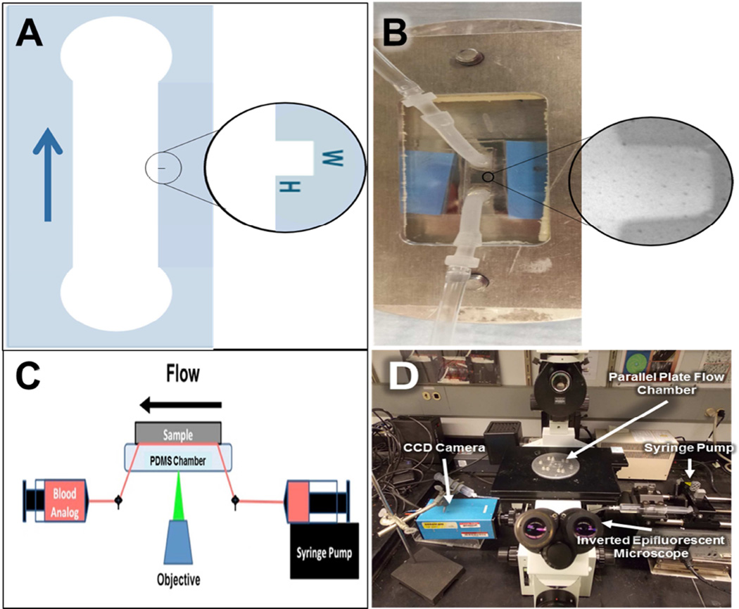
A custom parallel plate chamber was designed for this study. Flow channels containing crevices of defined dimensions were prepared from polydimethylsiloxane (PDMS) using a photo-etched silicon mold. The perfusion apparatus is shown in Figure 1. The main flow channel is 3 × 8 mm and includes one of three crevice dimensions (53 ± 7 × 122 ± 4 µm2 (n=7), 90 ± 12 × 122 ± 4 µm2 (N=7), or 137 ± 10 × 122 ± 4 µm2 (N=80). The height of the flow channel is 100 µm. Silicon tubing (Silcon® Med-X Tubing; United States Plastic Corporation, Lima, Ohio, USA) was connected to the PDMS channel as inlet and outlet connectors. A titanium alloy sample (Ti6Al4V; LaunchPoint Technologies Inc., Goleta, CA, USA) acted as the bottom plate of the chamber. Ti6Al4V was selected for study since it is employed by several current and experimental VADs for blood-contacting surfaces. [19] Platelet deposition on rat tail, type I collagen coated glass coverslips (Neuvitro Corporation, Vancouver, WA, USA; N=5) and a TiAl6V4 surface that had been modified with methacryloyloxyethyl phosphorylcholine polymer (MPC-Ti6Al4V, N=5) were employed as positive and negative thrombogenic control surfaces respectively. The control surfaces were employed in perfusions utilizing the 90 µm wide crevice. MPC-TI6AL4V was prepared in the authors’ laboratory using previously reported protocols [20]. The type I collagen coated cover slips were supplied by Neuvitro Inc. using their standard professional collagen coating procedure. Briefly, the coverslips were washed for 2 hr and then rinsed 6 times with sterile water for 30 min each, and then treated with 100% ethanol for 2 hr and 70% concentrated nitric acid for 24 hr. After rinsing the coverslips 6 times for 1 hr each, the G3 digital bio-coating system (Neuvitro) was utilized to coat them with 1mg/mL rat tail type 1 collagen for 24 hr at 4°C. The coverslips were rinsed twice in sterile water for 10 min and allowed to dry in the fume hood for 12 hr. A secondary coating was applied for 24 hr at 4°C and the coverslips were sterilized by radiation. A simple clamping mechanism held the plates together and acrylic shim stock was placed between the plates to provide a precisely defined channel height (Figure 1B). The flow within this chamber was assumed to be one-dimensional laminar parallel plate flow (Reynolds numbers between 0.1 and 0.4) [21, 22].
Figure 1.
Experimental Setup. A) Schematic of the flow path utilized in this study with magnified view of the rectangular crevice. The arrow indicates the direction of flow B) Photograph of parallel plate chamber with magnified view of the rectangular crevice. C) Schematic of the experimental layout. D) Photograph of the actual experimental layout.
Blood analog perfusion and image acquisition
All non-test surfaces were passivated by incubation with 1% bovine serum albumin (BSA, microbiological grade powder; MP Biomedicals, LLC, Solon, OH, USA) in PBS for 20 min prior to perfusion. The whole blood analog was collected into a 20 mL polystyrene syringe (BD Biosciences) and pushed through the parallel plate flow chamber by syringe pump (Harvard Apparatus, Holliston, Massachusetts, USA) for 10 min at flow rates of 0.125 and 0.310 mL/min (wall shear rates of 400 sec−1 and 1000 sec−1 respectively at the center of the channel). These wall shear rates were selected because they are representative of regions within VADs that often contain undesired steps and crevices. A wide range of wall shear rates are produced within the pumps of continuous flow VADs, including supra-physiological wall shear rates of >25,000 s-1 (shear stress >100 N m-2). [23–25] However, these high levels of shear are localized almost exclusively to the tips of the impeller blades. The wall shear rates represented in this study are characteristic of those regions most susceptible to platelet deposition, including the inlet and outlet connectors, upstream and downstream of the stators, and along the outer wall of centrifugal VADs. [23–25] Platelet deposition was visualized within the crevices, in real time, using an inverted epifluorescence microscope (Olympus IX FLA, Olympus Corporation, Shinjuku, Tokyo, Japan) with a 40× super long working distance objective (PlanFL, phase contrast, working distance 6.5 mm – 8.3 mm, numerical aperture 0.55; Olympus Corporation) and a 103W HBO short arc mercury lamp light source (OSRAM GmbH, Munich, Germany). Images were acquired every 0.4 sec beginning at one min after the start of perfusion using a CCD camera (PCO-TECH Inc., Romulus, Michigan, USA).
Fluorescent image analysis
The percent of the surface covered by deposited platelets was computed through established protocols. [18] Images were also analyzed to determine the probability of platelets adhering to a specific region within the crevice and the average intensity of the adherent platelets utilizing ImageJ (NIH, Bethesda, MD, USA) and custom designed MatLab (MathWorks, Inc., Natick, MA, USA) programs. Briefly, to calculate the probability of platelet adhesion, images were converted from grayscale to binary. All pixels that were brighter than a predetermined threshold were rendered white (platelets) and given a value of 1, whereas all pixels below that threshold were rendered black and given the value of 0. At discrete time points, the corresponding values of the pixels from each test were summed and divided by the total number of experiments. Intensity color maps were generated by averaging the intensity of the deposited platelets at discrete time points.
Computational Simulation
A model of flow within the crevices was developed to determine the shear rates within the crevices. Blood was treated as a linear fluid with dynamic viscosity of 3.0cP and density of 1060 kg/m3. The numerical simulations were performed using open source CFD software, OpenFOAM® (OpenCFD 2011). The geometries were discretized as hexahedral meshes using ICEM. In each of the cases, mesh-dependence studies were performed to assure insensitivity to the mesh size. Numerical results were visualized with ParaView, a post-processing utility for the solution of continuum mechanics problems. [26] The inflow rate was 310 µl/min and 125 µl/min. All the numerical results reached steady state condition.
Statistical analysis
All data are presented as mean ± standard error of the mean. Data were analyzed by two-way, repeated measures ANOVA with specific post- hoc testing using the Bonferroni correction. SPSS v23 (IBM Corp, Armonk, NY) was used for all statistical analyses.
Results
Probability of acute platelet adhesion
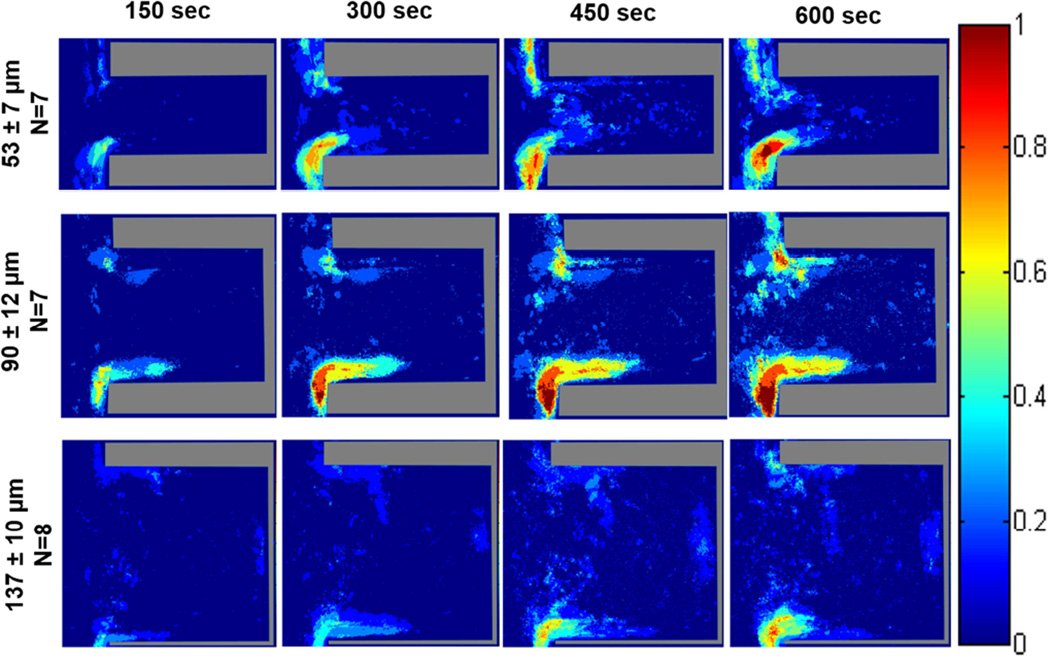
The probability maps generated from the acquired fluorescent images of platelet deposition within the various crevice sizes on TI6Al4V are displayed in Figures 2 and 3. In all color map images, flow in the main channel was directed downward. When the blood analog was perfused at a wall shear rate of 400 sec−1, the region with the greatest probability of adhesion for all three crevice sizes occurred at the distal corner, nearest the main channel (Figure 2). This region increased in area over time. After 10 min of perfusion a region on the proximal corner, nearest the main channel of the 53 µm and 90 µm crevices also contained a high probability of platelet adhesion (>75%). Adhesion was least likely to occur in the largest crevice (137 µm).
Figure 2.
Color maps depicting the local probability of platelet deposition within each crevice size, over time, at a perfusion rate of 125 µL/min and a wall shear rate of 400 sec−1. The direction of flow is down for the main channel, outside of the crevice.
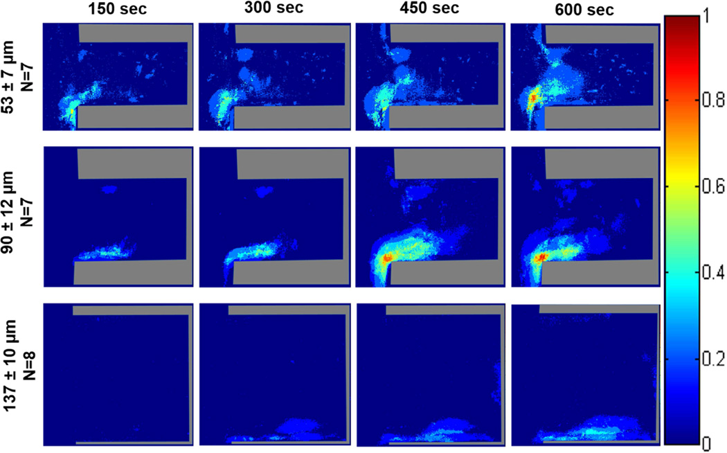
Figure 3.
Color maps depicting the probability of platelets depositing within each crevice size, over time, at a perfusion rate of 310 µL/min and a wall shear rate of 1000 sec−1. The direction of flow is down for the main channel, outside of the crevice.
Increasing the wall shear rate to 1000 sec−1 resulted in the greatest probability of platelet adhesion again being located at the distal corner, nearest the main channel for the 53 and 90 µm crevices (Figure 3). However this region did decrease in size with the increase in wall shear rate. Within the 137 µm crevice, the platelets mainly adhered along the distal wall with a maximum probability of adhesion <50%.
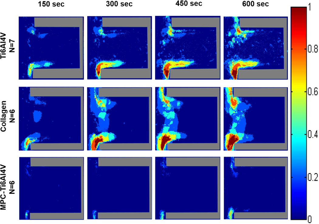
When comparing different surfaces at both wall shear rates, the greatest adhesion occurred on the type I collagen with regions having a high probability (>75%) of platelet adhesion being located at both the distal and proximal corner, nearest the main channel. Similar to Ti6Al4V, these regions of platelet adhesion increased with time. MPC-Ti6Al4V was the least thrombogenic with a maximum probability of platelet adhesion <30% in the limited region where this occurred (Figures 4 and S1). Upon increasing the wall shear rate from 400 to 1000 sec−1, platelets were more likely to adhere along the distal wall of MPC-Ti6Al4V instead of at the distal corner.
Figure 4.
Color maps depicting the probability of platelets depositing on each material, over time, at a perfusion rate of 125 µL/min and a wall shear rate of 400 sec−1. Crevice size of 90 ± 12 µm. The direction of flow is down for the main channel, outside of the crevice.
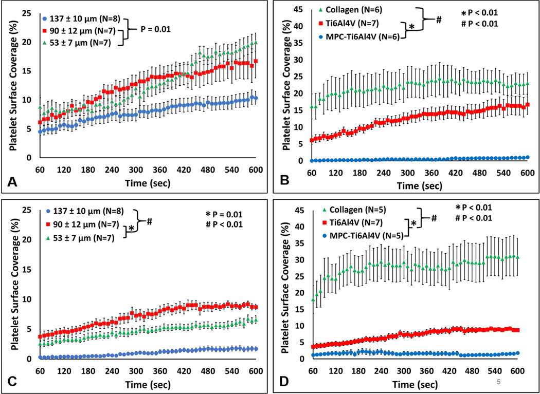
The fluorescent images were further analyzed to determine the percent of the analyzed blood contacting surface covered by adherent platelets over time (Figure 5). At the 400 sec−1 wall shear rate, the 53 µm and 90 µm crevice had significantly greater adhesion compared to the 137 µm crevice, with a platelet surface coverage of 19.9 ± 1.6%, 16.7 ± 2.9% and 10.4 ± 1.4% respectively. (P=0.01, Figure 5A). Comparing the materials, collagen had the greatest surface coverage with 23.1 ± 3.2% after 10 min of perfusion and MPC-Ti6Al4V had the least amount of adherent platelets with a maximum surface coverage of 1.1 ± 0.2 % (P<0.01, Figure 5B).
Figure 5.
The percent of the surface covered by deposited platelets. A) The effect of crevice size on platelet surface coverage at a wall shear rate of 400 sec−1. B) The effect of material on platelet surface coverage at a wall shear rate of 400 sec−1. Crevice size of 90 ± 12 µm. C) The effect of crevice size on platelet surface coverage at a wall shear rate of 1000 sec−1. D) The effect of material on platelet surface coverage at a wall shear rate of 1000 sec−1. Crevice size of 90 ± 12 µm.
Increasing the wall shear rate to 1000 sec−1 significantly decreased the percent platelet coverage within the 53 µm, 90 µm and the 137 µm (P<0.01, Figure S3). However, the increase in wall shear rate did not result in a significant change in adhesion for the collagen and MPC-Ti6Al4V samples (Figure 5C). At the higher wall shear rate, the 137 µm crevice had least amount of platelet deposition compared to the other crevice sizes at 1.7 ± 1.1% (P<0.01). The 90 µm crevice had significantly greater platelet coverage at 8.7 ± 0.5% compared to the 137 µm and 53 µm crevices (1.7 ± 1.1% and 6.6 ± 0.6% respectively, P<0.01).
Average intensity of deposited platelets
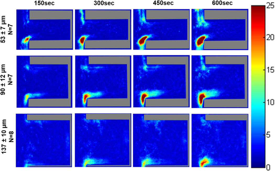
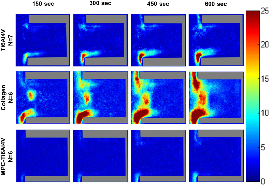
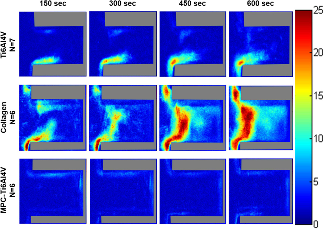
Color maps depicting the average fluorescence intensity from deposited platelets on Ti6Al4V (Figure 6 and Figure S2) and the control materials (Figure 7 and Figure 8) within the crevices were generated to provide a 3-dimensional approximation of thrombus formation, assuming that stacked platelets led to higher local fluorescence intensity.[27] The maximum intensity was set to 25, which was the maximum relative intensity measured when the collagen crevices were completely occluded. The greatest platelet deposition occurred on the collagen surface and the 90 µm crevice often became completely occluded after 10 min of perfusion. The images were thus normalized to the greatest average intensity exhibited by those collagen control surfaces that were completely occluded. At both wall shear rates the region of high platelet deposition (intensity >15; maximum intensity =25) occurred at the distal corner of the crevice nearest the main channel in the 53 and 90 µm crevices. However these regions of high platelet deposition were smaller in size when the blood analog was perfused at a higher wall shear rate. Platelets were least likely to deposit in the 137 µm crevice, and when the wall shear rate was increased to 1000 sec−1 for this crevice size, the average intensity decreased to <15.
Figure 6.
Color maps depicting the average intensity of the platelet deposition within each crevice size, over time, at a perfusion rate of 125 µL/min and a wall shear rate of 400 sec−1. The direction of flow is down for the main channel, outside of the crevice.
Figure 7.
Color maps depicting the average intensity of the platelet deposition on each material, over time, at a perfusion rate of 125 µL/min and a wall shear rate of 400 sec−1. The direction of flow is down for the main channel, outside of the crevice.
Figure 8.
Color maps depicting the average intensity of the platelet deposition on each material, over time, at a perfusion rate of 310 µL/min and a wall shear rate of 1000 sec−1. Crevice size of 90 ± 12 µm and the direction of flow is down for the main channel, outside of the crevice.
The greatest platelet deposition occurred on the type I collagen samples. The intensity images revealed that large thrombi formed along the entire entrance of the crevice, on the collagen coverslip. The least amount of deposition occurred on the MPC-Ti6Al4V samples with an average intensity <10.
Computational Simulation
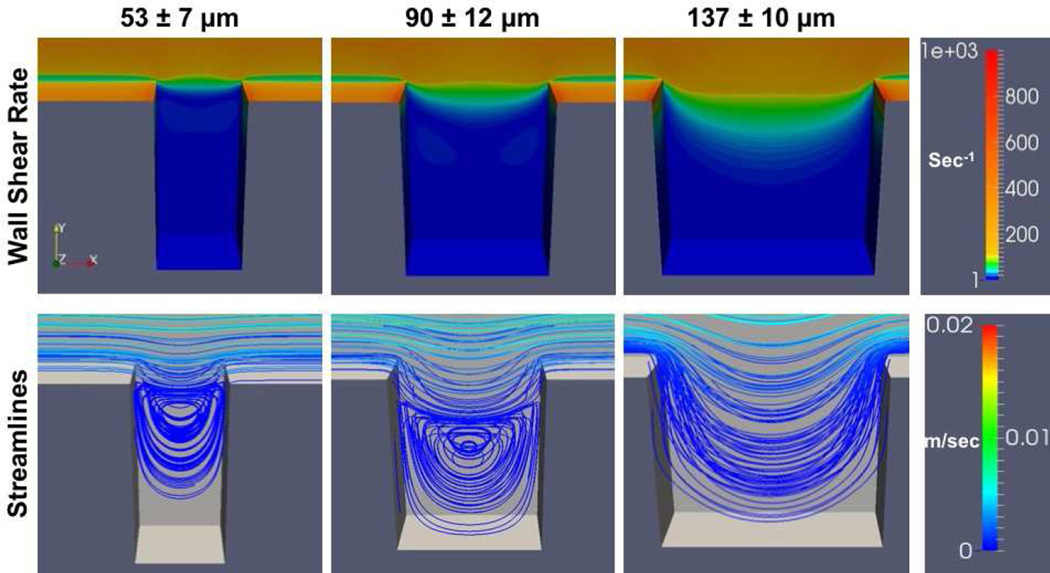
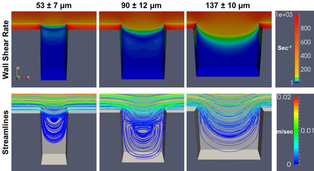
At both flow rates the greatest wall shear rates generated were located at the distal and proximal corners of the crevice closest to the main flow path (Figures 9 and 10). The wall shear rate decreased as fluid moved from the main channel into the crevices. Flow separation created a region of lower wall shear rate between the main flow channel and the mouth of the crevice. Within the 53 µm and 90 µm crevices, at both shear rates, the velocity streamlines indicated two flow regimes: the primary flow path that curves into the crevice from the main channel flow at the proximal corner, rejoining at the distal corner, and a secondary vortex that forms further within the crevice. Whereas for 137 µm, only the primary flow path that curves into the crevice was found.
Figure 9.
Computational simulation of the wall shear rates and flow fields within the crevices. The parameters are presented for the surface of the test material (i.e. the back wall in the image). Wall shear rate at the center of the main flow channel is 400 sec−1
Figure 10.
Computational simulation of the wall shear rates and flow fields within the crevices. The parameters are presented for the surface of the test material (i.e. the back wall in the image). Wall shear rate at the center of the main flow channel is 1000 sec−1
Representative real-time perfusion videos
Representative accelerated videos of platelets depositing within the crevices for different materials and the two wall shear rates are available in the Supplemental Material (Videos S1–S7). Unlike the computational flow simulations, the two flow regimes (the primary flow path that curves into the crevice from the main channel flow at the proximal corner and rejoins the main channel flow at the distal corner, and a secondary vortex that forms further within the crevice) are visible within all three crevice sizes and both wall shear rates. The diameter of the vortex decreased in size with the decrease in crevice width. In the 53 µm and 90 µm crevices (Videos S1 and S2), the platelets initially adhered to the distal corner, nearest the main channel, and grew upward toward the center of the crevice. As the thrombi grew and partially occluded the crevice, the vortex was disturbed and the flow within the crevice became more unstable. When the wall shear rate was increased to 1000 sec−1, the stability of the thrombi decreased and more embolization events were observed (Videos 3S and 4S). Only a few embolization events were noted within the 137 µm crevice or on the MPC-Ti6Al4V at both wall shear rates (Videos S5 and S6).
Discussion
Biomaterial-centered thrombosis and its subsequent thromboembolism remain of high relevance as designers seek to improve the blood biocompatibility of future generation VADs and other cardiovascular devices. Recent reports have shown an unexpected increase in thromboembolic events in patients who have received two of the most popular continuous flow VADs (HeartMate II, Thoratec, Pleasanton, CA; HVAD, HeartWare, Framingham, MA) [28–30], leading the US Food and Drug Administration to issue a safety communication stating that the potential risk associated with the use of these devices is greater than originally reported at the time of regulatory approval. [29] The timeliness of a more thorough investigation into the potential triggers for thrombotic deposition in VADs is thus clear, and this challenge extends to several other blood-contacting medical devices.
The fluid flow pathway within a blood-wetted medical device is an important determinant of the likelihood for thrombus development and subsequent embolization. According to Virchow’s triad, it is one of the three major factors that affect thrombosis along with surface and the status of the blood. [31] Therefore, it is important to consider blood flow patterns when designing cardiac devices and selecting blood contacting biomaterials. Several studies have used PIV to characterize fluid flow within irregular geometries, such as bifurcations, steps, and crevices, and in specific cardiovascular devices in order to identify regions that could potentially promote thrombus formation.[7,32–35] Studies using this method have been able to ascertain potentially hazardous flow patterns (i.e. recirculation and stagnation). However, platelet-sized particles [34, 35] or red blood cells in platelet poor plasma [7,32] are used in this technique as the tracing particles instead of biologically active platelets.
Many microfluidic devices have been designed to investigate the effect of the blood flow pathway on the development of thrombi. Unlike PIV, this technique utilizes active platelets to characterize how disturbed flow contributes to platelet adhesion and aggregation.[14, 35,36] The majority of these studies examine platelet deposition onto collagen-coated or uncoated glass coverslips after backward steps, sudden expansions, or stenosis.[9,13, 36,37]
Few studies have examined how complex flow paths affect the adhesion or deposition of platelets onto a biomaterial.[16, 17] Goodman et al. [16] used an experimental flow cell consisting of polyethylene tubing with sudden constrictions. Heparinized human blood was perfused through flow cells and thrombus growth was observed with video-microscopy. It was found that there were three regions of substantial platelet deposition; at the point of contraction, at the point of expansion, and at the flow reattachment point. Schaller et al. [17] developed a stagnation flow chamber to examine how flow stagnation and a continuum of wall shear rates affected platelet adhesion onto glass coverslips that were thinly coated with commercial polyurethanes or adsorbed von-Willebrand factor as their test materials. Although these techniques provide a way to examine real-time platelet deposition onto biomaterials, the flow conditions are not related to the defects or design attributes of many cardiovascular devices
Previous PIV studies of sudden expansions and constrictions revealed that the highest concentration of platelet sized particles was in the corners, where there were regions of recirculating flow.[7, 16] These results would suggest that the greatest platelet deposition would have been located towards the back of the crevices where the secondary vortices formed. However, it was found here that the regions of greatest deposition occurred on the distal corners of the crevices toward the main channel. This may have occurred because the distal corner is the first area the platelets impact, and the secondary flow vortex pattern increases the cumulative time that platelets can interact with this area. Once platelets adhere and activate within this region, they release their granules and initiate biochemical pathways that result in a local flux of platelet agonists, creating a positive feedback loop that promotes further deposition. Ha et el. [36] and Taylor et al. [38] found that platelet deposition onto collagen initially occurred on the edge of a sudden expansion but then progressed into the corner. The crevices are similar to a sudden expansion followed quickly by a sudden constriction. This creates two distinct flow paths: the secondary flow vortex pattern and the primary flow path that curves into the crevice from the main channel flow at the proximal corner and then rejoins the main channel flow at the distal corner. This primary flow path would transport platelets away from the crevice after some potential interaction with the distal corner, and may be why the thrombus does not grow into the bottom of the crevice.
Cardiovascular device manufacturers generally try to minimize the size of discontinuities and crevices within their devices to intuitively reduce their potential to promote thrombus formation. However, in the size range examined, it was found that the largest crevice was the least thrombogenic. Through the simulations (Figures 9 and 10), the wall shear rates in and near the crevice were modestly larger for the larger crevice cases, and at the same time less platelet deposition was observed from the experiments. This may be reasonable in that shear-related convection (cleaning) could reduce the local concentration of secreted and formed platelet agonists, reduce local platelet residence time and thus reduce local deposition. The dissimilarity between the velocity streamlines produced by the simulation and the flow path qualitatively observed in the video from the 137 µm crevice (Video S5) may be due to the non-Newtonian nature of the blood analog which was not considered in the computational simulation. However, the real-time videos show that platelets tended to remain trapped in the vortices of the 53 and 90 µm crevices for an extended period of time when compared to the 137 µm crevice. Therefore although platelets in the 137 µm crevice were exposed to the disturbed flow patterns, artificial material, and biochemical agonist, it was for a shorter period of time when compared to the other crevice sizes, making it less likely they would activate and adhere.
The computational simulations and real-time flow with labeled platelets indicated that when the ratio of the width to depth (w/d) of the crevice was decreased, the areas of stagnation and recirculation increased. This phenomenon is well characterized in the literature [39], and such regions of recirculation and stagnation have been generally associated with platelet activation and adhesion. [7–10] One could hypothesize that reducing the depth of the crevice would decrease the thrombogenicity of the feature. Future studies using this crevice perfusion system could potentially validate this hypothesis.
Although this was an acute study, the real-time visualization method employed provides the ability to investigate the initiation and potentiation of thrombus deposition generated by irregular geometries with opaque materials. For example, the color maps and surface coverage analysis suggest that when one increases the shear rate to 1000 sec−1, platelet adhesion within the 53 µm crevice decreases. However, the videos show that the thrombi that form in the crevice are not stable. In Video S3 the thrombus that formed in the 53 µm crevice rotates with the secondary vortex. Often times this unstable thrombus would embolize, an effect not perceivable with endpoint analysis. This method also provides a way to investigate how the growth of thrombi affects the flow pattern within the crevice. As the deposition increases within the 53 µm and 90 µm crevices the flow becomes erratic, altering the shape of the secondary vortex.
The hemocompatibility of biomaterials is greatly influenced by the adsorption of plasma proteins to the surface. Several studies on polymeric surfaces have indicated that initial platelet adhesion is mediated by fibrinogen adsorbed in a recognized conformation that exposes GPIIb/IIIa binding sites, while GPIb is required for the development of vertical thrombus growth. [40–41] Although the mechanism for platelet adhesion to titanium alloys is not as well characterized, studies utilizing specific platelet inhibitors, suggest that platelet adhesion is also mediated by GPIIa/IIIb binding to surface adhered fibrinogen [42, 43] Future studies with the described crevice perfusion system could evaluate the impact of specific adhesion receptor blockade on the morphology and extent of crevice-associated platelet deposition.
The results from this study indicate that utilizing MPC-Ti6Al4V decreases platelet deposition within the crevices when compared to the unmodified titanium alloy. A reduction in fibrinogen absorption to the MPC modified surface may contribute to its decreased thrombogenicity. Fibrinogen absorption under static conditions onto both Ti6Al4 and a zwitterionic modified MPC-Ti6Al4V has been previously investigated by Ye at el. [20]. Comparing samples of MPC-modified and unmodified titanium alloy incubated in ovine fibrinogen for 3 hr showed that MPC-Ti6Al4V had significantly reduced fibrinogen adsorption compared to the unmodified titanium alloy. There are several limits to interpreting this result in that first a pure protein solution was used, so no Vroman effect was possible, and second, no fluid shear was present during the protein adsorption. Since the zwitterionic modification likely broadly reduced protein adsorption, and the data suggest that adsorbed proteins are facilitating the adhesion events, but it is not clear if this adhesion is primarily facilitated by fibrinogen, vWF, or other plasma proteins.
Several mathematical and computer models have been developed to try to predict platelet deposition and thrombus formation with simple flow paths.[16, 44] Some researchers have even incorporated flow over a step as part of their modeling.[44] However, the interpretation of these models is limited by the lack of experimental data characterizing the effects of steps and crevices, or the effect of common clinical biomaterials on thrombus formation. A robust predictive model of device thrombosis would reduce the time and resources spent in empirically seeking to design more blood-biocompatible cardiovascular devices. The methodology employed in this study and the type of data generated provides a means for the refinement and fitting of models that seek to simulate the thrombotic deposition process in blood-wetted devices
Some limitations of the current report are worth noting. Aside from the aforementioned acute nature of the blood perfusion experiments, the results are also limited by the 2D nature of the flow pathway. The biomaterial only comprised the bottom (imaged) surface of the flow chamber. The other surfaces of the channel were albumin-passivated PDMS, in an effort to minimize any effects from platelet deposition onto non-test material. Etching the flow path directly into a Ti6Al4V surface may be possible to create only one non-test surface, however etch techniques that were evaluated (data not shown) were not able to achieve the precision or tolerance necessary to make a crevice with smooth, well defined walls. Further, the use of a PDMS channel allowed multiple materials to be tested with a consistently shaped geometry. Another limitation was that only three crevice sizes were investigated. Limitations on the size range evaluated were the tolerance of the photo-etching technique employed and the field of view associated with the optical system. A rectangular geometry was chosen to represent an idealized crevice because the fluid flow within it has been well-characterized. [39] This isolated crevice is analogous to a “control volume” approach commonly used in engineering, in which the influences far from the region of interest are replaced by consequential boundary conditions surrounding the control volume and therefore this geometry is readily amenable to computational modeling.
For these studies sodium citrate was selected as the anticoagulant, which is necessary to permit blood handling after the blood draw and to prevent occlusion in the perfusion system. Heparin anticoagulation would be an alternative, albeit with some concern for heparin-mediated platelet activation. [45–46.] The use of citrate would be associated with reduced local thrombin generation. It is known that thrombin plays an important role in facilitating platelet deposition in similar perfusion studies, albeit without a crevice. [27] Anti-platelet medication was not utilized for the perfusion experiments. Anti-platelet medications have been incorporated in previous studies investigating mechanisms of platelet deposition [47, 48]. Tovar-Lopez et al. found that platelet aggregates formed downstream of a stenosis, even when the platelets were significantly inhibited by anti-platelet agents, suggesting that this aggregation was mediated mainly by mechanical effects of blood flow. Tovar-Lopez et al. exposed blood to shear rates of around 19,000 sec−1 at the stenosis whereas the study described in this manuscript only investigates main perfusion channel wall shear rates on the order of 1000 sec−1 [47] Although many VAD patients are prescribed an antiplatelet medication, typically aspirin, this is not a standard practice, and depends on the institution. In most centers, these patients are initially treated only with heparin after implantation. [49], followed by transition to coumadin. Thus, a blood analog that does not specifically contain anti-platelet agents has relevance in evaluating the acute in-vitro hemocompatibility of biomaterials and flow path geometries used in these devices.
The reconstituted blood perfusate used in this report included a dilute suspension of red blood cells (25% hematocrit). Although this is lower than the average hematocrit for healthy individuals, it is not atypical for patients implanted with VADs. Woolley et al. reported that the average hematocrit of continuous flow VAD patients was less than 30% for the first 30 days after implantation (N= 46). [50] In another study by Boyle et al. it was reported that patients who received a HeartMate II had an average hermatocrit of 30.7 % ranging from 27.5% to 33.7% at discharge (N=331). [51]
Conclusions
The employed temporal visualization method provides a viable means for quantifying the effect of common geometric irregularities found in cardiovascular devices on platelet deposition. Interestingly, the least amount of deposition occurred in the largest crevice size, while the most deposition occurred in the 90 µm and 53 µm crevices at the lower wall shear rate. The data suggest that the crevice size might be tailored, depending on the flow conditions, to reduce the risk of thromboembolic events. Further, these type of data could be applied to improve the accuracy of a predictive model of thrombotic deposition in VADs to help determine the tolerable limits of these features. Such limits could then be incorporated into the design of blood-wetted, implantable cardiovascular devices to improve hemocompatibility and reduce complications associated with thrombosis and thromboembolism.
Supplementary Material
Acknowledgments
The assistance of Fang Yang, Collin Edington, and Andrea Marten in the design and production of the crevice flow channels are acknowledged. We thank Dr. Sang-Ho Ye for providing the MPC-TI6AL4V coated samples. We thank Jackie Chen and Carnegie Mellon University’s Center for Bioimage Informatics for their assistance in developing the image analysis MatLab program, and the University of Pittsburgh’s Clinical and Translational Science Institute (CTSI) for assisting in donor recruitment.
Support was provided in part by the Cardiovascular Bioengineering Training Program (NIH Training Grant T32-HL076124), Cellular Approaches to Tissue Engineering and Regenerative Medicine (CATER, NIH Training Grant T32-EB001026), ARCS Foundation, NIH Contract No. HHSN268200448192C, NIH Grant R01 HL089456-01, and the McGowan Institute for Regenerative Medicine.
Footnotes
Publisher's Disclaimer: This is a PDF file of an unedited manuscript that has been accepted for publication. As a service to our customers we are providing this early version of the manuscript. The manuscript will undergo copyediting, typesetting, and review of the resulting proof before it is published in its final citable form. Please note that during the production process errors may be discovered which could affect the content, and all legal disclaimers that apply to the journal pertain.
References
- 1.Kirklin JK, Naftel DC, Kormos RL, Stevenson LW, Pagani FD, Miller MA, et al. Fifth INTERMACS annual report: risk factor analysis from more than 6,000 mechanical circulatory support patients. J Heart Lung Transplant. 2013;32:141–156. doi: 10.1016/j.healun.2012.12.004. [DOI] [PubMed] [Google Scholar]
- 2.Eckman PM, John R. Bleeding and Thrombosis in Patients With Continuous-Flow Ventricular Assist Devices. Circulation. 2012;125:3038–3047. doi: 10.1161/CIRCULATIONAHA.111.040246. [DOI] [PubMed] [Google Scholar]
- 3.Adzic A, Patel SR, Maybaum S. Impact of adverse events on ventricular assist device outcomes. Curr Heart Fail Rep. 2013;10:89–100. doi: 10.1007/s11897-012-0127-3. [DOI] [PubMed] [Google Scholar]
- 4.Slaughter MS. Hematologic effects of continuous flow left ventricular assist devices. J Cardiovasc Transl Res. 2010;3:618–624. doi: 10.1007/s12265-010-9222-6. [DOI] [PubMed] [Google Scholar]
- 5.Bluestein D, Chandran KB, Manning KB. Towards non-thrombogenic performance of blood recirculating devices. Ann Biomed Eng. 2010;38:1236–1256. doi: 10.1007/s10439-010-9905-9. [DOI] [PMC free article] [PubMed] [Google Scholar]
- 6.Wagner WR, Schaub RD, Sorensen EN, Snyder TA, Wilhelm CR, Winowich S, et al. Blood biocompatibility analysis in the setting of ventricular assist devices. J Biomater Sci Polym Ed. 2000;11:1239–1259. doi: 10.1163/156856200744183. [DOI] [PubMed] [Google Scholar]
- 7.Zhao R, Marhefka JN, Shu F, Hund SJ, Kameneva MV, Antaki JF. Micro-flow visualization of red blood cell-enhanced platelet concentration at sudden expansion. Ann Biomed Eng. 2008;36:1130–1141. doi: 10.1007/s10439-008-9494-z. [DOI] [PMC free article] [PubMed] [Google Scholar]
- 8.Karino T, Goldsmith HL. Aggregation of Human Platelets in an Annular Vortex Distal to a Tubular Expansion. Microvascular Research. 1979;17:217–237. doi: 10.1016/s0026-2862(79)80001-1. [DOI] [PubMed] [Google Scholar]
- 9.Karino T, Goldsmith HL. Adhesion of Human Platelets to Collagen on the Walls Distal to a Tubular Expansion. Microvascular Research. 1979;17:238–262. doi: 10.1016/s0026-2862(79)80002-3. [DOI] [PubMed] [Google Scholar]
- 10.Mandrusov E, Puszkin E, Vroman L, Leonard E. Separated Flows in Artificial Organs: A Cause of Early Thrombogenesis? ASAIO Journal. 1996;42:M506–M513. doi: 10.1097/00002480-199609000-00038. [DOI] [PubMed] [Google Scholar]
- 11.Ahn T, Shin E, Merhi Y, Thai P, Bilodeau L. Influence of stent expansion states on platelet deposition in an extracorporeal porcine arteriovenous shunt model using a multichannel perfusion chamber. J Korean Med Sci. 2001;16:31–38. doi: 10.3346/jkms.2001.16.1.31. [DOI] [PMC free article] [PubMed] [Google Scholar]
- 12.Alemu Y, Bluestein D. Flow-induced platelet activation and damage accumulation in a mechanical heart valve: numerical studies. Artif Organs. 2007;31:677–688. doi: 10.1111/j.1525-1594.2007.00446.x. [DOI] [PubMed] [Google Scholar]
- 13.Wootton DM, Markou CP, Hanson SR, Ku DN. A Mechanistic Model of Acute Platelet Accumulation in Thrombogenic Stenoses. Ann Biomed Eng. 2001;29:321–329. doi: 10.1114/1.1359449. [DOI] [PubMed] [Google Scholar]
- 14.YIin W, Alemu Y, Affeld K, Jesty J, Bluestein D. Flow-Induced Platelet Activation in Bileaflet and Monoleaflet Mechanical Heart Valves. Ann Biomed Eng. 2004;23:1058–1066. doi: 10.1114/b:abme.0000036642.21895.3f. [DOI] [PubMed] [Google Scholar]
- 15.Timms D, Hayne M, Tan A, Pearcy M. Evaluation of left ventricular assist device performance and hydraulic force in a complete mock circulation loop. Artif Organs. 2005;29:573–580. doi: 10.1111/j.1525-1594.2005.29093.x. [DOI] [PubMed] [Google Scholar]
- 16.Goodman PD, Barlow ET, Crapo PM, Mohammad SF, Solen KA. Computational Model of Device-Induced Thrombosis and Thromboembolism. Ann Biomed Eng. 2005;33:780–797. doi: 10.1007/s10439-005-2951-z. [DOI] [PubMed] [Google Scholar]
- 17.Schaller J, Kragh T, Reininger A, Goubergrits L, Kertzscher U, Spannagl M, et al. Biocompatibility Material Test for Cardiovascular Devices using Stagnation Point Flow. Biomedical Engineering / Biomedizinische Technik. 2013 doi: 10.1515/bmt-2013-4366. [DOI] [PubMed] [Google Scholar]
- 18.Jamiolkowski MA, Woolley JR, Kameneva MV, Antaki JF, Wagner WR. Real time visualization and characterization of platelet deposition under flow onto clinically relevant opaque surfaces. J Biomed Mater Res A. 2015;103:1303–1311. doi: 10.1002/jbm.a.35202. [DOI] [PMC free article] [PubMed] [Google Scholar]
- 19.Sin DC, Kei HL, Miao X. Surface coatings for ventricular assist devices. Expert Rev Med Devices. 2009;6:51–60. doi: 10.1586/17434440.6.1.51. [DOI] [PubMed] [Google Scholar]
- 20.Ye SH, Johnson CA, Jr, Woolley JR, Murata H, Gamble LJ, Ishihara K, et al. Simple surface modification of a titanium alloy with silanated zwitterionic phosphorylcholine or sulfobetaine modifiers to reduce thrombogenicity. Colloids Surf B Biointerfaces. 2010;79:357–364. doi: 10.1016/j.colsurfb.2010.04.018. [DOI] [PMC free article] [PubMed] [Google Scholar]
- 21.Schaub R, Kameneva M, Borovetz H, Wagner W. Assessing acute platelet adhesion on opaque metallic and polymeric biomaterials with fiber optic microscopy. J Biomed Mater Res A. 2000;49:460–468. doi: 10.1002/(sici)1097-4636(20000315)49:4<460::aid-jbm4>3.0.co;2-3. [DOI] [PubMed] [Google Scholar]
- 22.Kent NJ, Basabe-Desmonts L, Meade G, MacCraith BD, Corcoran BG, Kenny D, et al. Microfluidic device to study arterial shear-mediated platelet-surface interactions in whole blood: reduced sample volumes and well-characterised protein surfaces. Biomed Microdevices. 2010;12:987–1000. doi: 10.1007/s10544-010-9453-y. [DOI] [PubMed] [Google Scholar]
- 23.Song X, Throckmorton AL, Wood HG, Antaki JF, Olsen DB. Quantitative Evaluation of Blood Damage in a Centrifugal VAD by Computational Fluid Dynamics. J. Fluids Eng. 2004;126(3):410–418. [Google Scholar]
- 24.Wu J, Paden BE, Borovetz HS, Antaki JF. Computational fluid dynamics analysis of blade tip clearances on hemodynamic performance and blood damage in a centrifugal ventricular assist device. Artif Organs. 2010;34(5):402–411. doi: 10.1111/j.1525-1594.2009.00875.x. [DOI] [PMC free article] [PubMed] [Google Scholar]
- 25.Zhang Y, Zhan Z, Gui XM, Sun HS, Zhang H, Zheng Z, Zhou JY, Zhu XD, Li GR, Hu SS, Jin DH. Design optimization of an axial blood pump with computational fluid dynamics. ASAIO J. 2008;54(2):150–155. doi: 10.1097/MAT.0b013e318164137f. [DOI] [PubMed] [Google Scholar]
- 26.Henderson A, Ahrens J, Law C. The ParaView Guide. Clifton Park, NY: Kitware Inc.; 2004. [Google Scholar]
- 27.Wagner WR, Hubbell JA. Local thrombin synthesis and fibrin formation in an in vitro thrombosis model result in platelet recruitment and thrombus stabilization on collagen in heparinized blood. J Lab Clin Med. 1990;116:636–650. [PubMed] [Google Scholar]
- 28.Starling RC, Moazami N, Silvestry SC, Ewald G, Rogers JG, Milano CA, et al. Unexpected abrupt increase in left ventricular assist device thrombosis. N Engl J Med. 2014;370:33–40. doi: 10.1056/NEJMoa1313385. [DOI] [PubMed] [Google Scholar]
- 29.FDA. Serious Adverse Events with Implantable Left Ventricular Assist Devices (LVADs): FDA Safety Communication. 2015 Available at http://wwwfdagov/MedicalDevices/Safety/AlertsandNotices/ucm457327htm.
- 30.Kirklin JK, Naftel DC, Kormos RL, Pagani FD, Myers SL, Stevenson LW, et al. Interagency Registry for Mechanically Assisted Circulatory Support (INTERMACS) analysis of pump thrombosis in the HeartMate II left ventricular assist device. J Heart Lung Transplant. 2014;33:12–22. doi: 10.1016/j.healun.2013.11.001. [DOI] [PubMed] [Google Scholar]
- 31.Lowe GD. Virchow's triad revisited: abnormal flow. Pathophysiol Haemost Thromb. 2003;33:455–457. doi: 10.1159/000083845. [DOI] [PubMed] [Google Scholar]
- 32.Sherwood JM, Kaliviotis E, Dusting J, Balabani S. Hematocrit, viscosity and velocity distributions of aggregating and non-aggregating blood in a bifurcating microchannel. Biomech Model Mechanobiol. 2014;13:259–273. doi: 10.1007/s10237-012-0449-9. [DOI] [PubMed] [Google Scholar]
- 33.Wereley ST, Meinhart CD. Recent Advances in Micro-Particle Image Velocimetry. Annu Rev Fluid Mech. 2010;42:557–576. [Google Scholar]
- 34.Yang F, Kormos RL, Antaki JF. High-speed visualization of disturbed pathlines in axial flow ventricular assist device under pulsatile conditions. J Thorac Cardiovasc Surg. 2015 doi: 10.1016/j.jtcvs.2015.06.049. [DOI] [PMC free article] [PubMed] [Google Scholar]
- 35.Burgreen G, Antaki J, Wu J, Blanc Pl, Butler K. A computational and experimental comparison of two outlet stators for the Nimbus LVAD. Left ventricular assist device. ASAIO J. 1999;45:328–333. doi: 10.1097/00002480-199907000-00014. [DOI] [PubMed] [Google Scholar]
- 36.Ha H, Lee SJ. Hemodynamic features and platelet aggregation in a stenosed microchannel. Microvasc Res. 2013;90:96–105. doi: 10.1016/j.mvr.2013.08.008. [DOI] [PubMed] [Google Scholar]
- 37.Li M, Ku DN, Forest CR. Microfluidic system for simultaneous optical measurement of platelet aggregation at multiple shear rates in whole blood. Lab Chip. 2012;12:1355–1362. doi: 10.1039/c2lc21145a. [DOI] [PubMed] [Google Scholar]
- 38.Taylor JO, Witmer KP, Neuberger T, Craven BA, Meyer RS, Deutsch S, et al. In vitro quantification of time dependent thrombus size using magnetic resonance imaging and computational simulations of thrombus surface shear stresses. J Biomech Eng. 2014:136. doi: 10.1115/1.4027613. [DOI] [PubMed] [Google Scholar]
- 39.Dyke MV. An album of fluid motion. Stanford, CA: Parabolic Press; 1982. [Google Scholar]
- 40.Sheppeck RA, Bentz M, Dickson C, et al. Examination of the roles of glycoprotein Ib and glycoprotein IIb/IIIa in a platelet deposition on an artificial surface using clinical antiplatelet agents and monoclonal antibody blockade. Blood. 1991;78:673–680. [PubMed] [Google Scholar]
- 41.Lindon JN, McManama G, Kushner L, Merrill EW, Salzman EW. Does the Conformation of Adsorbed Fibrinogen Dictate Platelet Interactions with Artificial Surfaces. Blood. 1986;68(2):355–362. [PubMed] [Google Scholar]
- 42.Broberg M, Eriksson C, Nygren H. GpIIb/IIIa is the main receptor for initial platelet adhesion to glass and titanium surfaces in contact with whole blood. J Lab Clin Med. 2002 Mar;139(3):163–172. doi: 10.1067/mlc.2002.121604. [DOI] [PubMed] [Google Scholar]
- 43.Linneweber J, Dohmen PM, Kertzscher U, et al. Local glycoprotein IIb/IIIa receptor inhibitor delivery from the pump surface attenuates platelet adhesion in continuous flow ventricular assist devices. Artif Organs. 2008 Oct;32(10):792–799. doi: 10.1111/j.1525-1594.2008.00632.x. [DOI] [PubMed] [Google Scholar]
- 44.Tamagawa M, Kaneda H, Hiramoto M, Nagahama S. Simulation of thrombus formation in shear flows using Lattice Boltzmann Method. Artificial organs. 2009;33:604–610. doi: 10.1111/j.1525-1594.2009.00782.x. [DOI] [PubMed] [Google Scholar]
- 45.Golanski J, Pietrucha T, Baj Z, Greger J, Watala C. Molecular insights into the anticoagulant-induced spontaneous activation of platelets in whole blood-various anticoagulants are not equal. Thromb Res. 1996;83:199.55–216.55. doi: 10.1016/0049-3848(96)00129-6. [DOI] [PubMed] [Google Scholar]
- 46.Harding SA, Din JN, Sarma J, Jessop A, Weatherall M, Fox KA, Newby DE. Flow cytometric analysis of circulating platelet-monocyte aggregates in whole blood: Methodological considerations. Thromb Haemost. 2007;98:451–456. [PubMed] [Google Scholar]
- 47.Tovar-Lopez FJ, Rosengarten G, Nasabi M, Sivan V, Khoshmanesh K, Jackson SP, et al. An investigation on platelet transport during thrombus formation at micro-scale stenosis. PloS one. 2013;8:e74123. doi: 10.1371/journal.pone.0074123. [DOI] [PMC free article] [PubMed] [Google Scholar]
- 48.Nesbitt WS, Westein E, Tovar-Lopez FJ, Tolouei E, Mitchell A, et al. A shear gradient dependent platelet aggregation mechanism drives thrombus formation. Nat Med. 2009;15:665673. doi: 10.1038/nm.1955. [DOI] [PubMed] [Google Scholar]
- 49.Baumann Kreuziger LM, Kim B, Wieselthaler GM. Antithrombotic therapy for left ventricular assist devices in adults: a systematic review. J Thromb Haemost. 2015;13(6):946–955. doi: 10.1111/jth.12948. [DOI] [PubMed] [Google Scholar]
- 50.Woolley JR, Teuteberg JJ, Bermudez CA, Bhama JK, Lockard KL, Kormos RL, et al. Temporal leukocyte numbers and granulocyte activation in pulsatile and rotary ventricular assist device patients. Artif Organs. 2013;38:447–455. doi: 10.1111/aor.12200. [DOI] [PMC free article] [PubMed] [Google Scholar]
- 51.Boyle AJ, Russell SD, Teuteberg JJ, Slaughter MS, Moazami N, Pagani FD, et al. Low thromboembolism and pump thrombosis with the HeartMate II left ventricular assist device: analysis of outpatient anti-coagulation. J Heart Lung Transplant. 2009;28(9):881–887. doi: 10.1016/j.healun.2009.05.018. [DOI] [PubMed] [Google Scholar]
Associated Data
This section collects any data citations, data availability statements, or supplementary materials included in this article.


