We design a self-powered materials system that transduces chemical, mechanical, and electrical energy to perform computation.
Keywords: Materials that compute, pattern recognition, hybrid material, polymer gel, chemo-mechanical oscillations, Belousov-Zhabotinsky reaction, piezoelectric sensor and actuator
Abstract
Driven by advances in materials and computer science, researchers are attempting to design systems where the computer and material are one and the same entity. Using theoretical and computational modeling, we design a hybrid material system that can autonomously transduce chemical, mechanical, and electrical energy to perform a computational task in a self-organized manner, without the need for external electrical power sources. Each unit in this system integrates a self-oscillating gel, which undergoes the Belousov-Zhabotinsky (BZ) reaction, with an overlaying piezoelectric (PZ) cantilever. The chemomechanical oscillations of the BZ gels deflect the PZ layer, which consequently generates a voltage across the material. When these BZ-PZ units are connected in series by electrical wires, the oscillations of these units become synchronized across the network, where the mode of synchronization depends on the polarity of the PZ. We show that the network of coupled, synchronizing BZ-PZ oscillators can perform pattern recognition. The “stored” patterns are set of polarities of the individual BZ-PZ units, and the “input” patterns are coded through the initial phase of the oscillations imposed on these units. The results of the modeling show that the input pattern closest to the stored pattern exhibits the fastest convergence time to stable synchronization behavior. In this way, networks of coupled BZ-PZ oscillators achieve pattern recognition. Further, we show that the convergence time to stable synchronization provides a robust measure of the degree of match between the input and stored patterns. Through these studies, we establish experimentally realizable design rules for creating “materials that compute.”
INTRODUCTION
Prompted by recent developments in stimuli-responsive materials (1) and nonconventional computing (2–4), researchers are attempting to bridge these fields to create “materials that compute,” where the computer and the material are one and the same entity (5, 6). Ideally, these materials would perform functions such as sensing, communicating, and computing in a relatively autonomous manner, enabling them to operate without connections to an external power supply. One means of achieving these objectives is to integrate the capabilities of energy-transducing, soft materials, such as oscillating chemical gels, and modes of computation, such as oscillator-based computing (2), which can exploit these materials characteristics. The design of stand-alone “fabrics” that take input from the environment and then process and transmit information can facilitate the creation of new types of “smart” clothing and sensorial robotics, as well as expand the functionality of everyday objects (6).
Recently, we used theory and simulation to lay out design principles for one class of materials that compute (5). The fundamental unit in this system is composed of a polymer gel undergoing the Belousov-Zhabotinsky (BZ) oscillatory reaction and an overlaying piezoelectric (PZ) bimorph cantilever (see Fig. 1). In these studies, we exploited the inherent properties of the materials to achieve the desired autonomous functionality. Namely, the BZ gels oscillate periodically without the need for external stimuli; the rhythmic pulsations are fueled by the BZ reaction occurring within the polymer network (7). Moreover, PZs spontaneously generate a voltage when deformed and, conversely, undergo deformation in the presence of an applied voltage. By combining these attributes into a “BZ-PZ” unit and then connecting the units by electrical wires, we designed a device that senses, actuates, and communicates without an external electrical power source. Here, we show that the device can also be used to perform computation, ultimately enabling materials that compute.
Fig. 1. Two BZ-PZ oscillator units connected with electrical wires.

Each PZ cantilever consists of two identical layers of a polarized PZ material; the internal and external surfaces are covered with thin electrodes connected in parallel. Periodic volumetric changes in the self-oscillating BZ gels cause rhythmic bending of the PZ plates. The vector of polarization in PZ bending plates is oriented perpendicular to the plate surface (not shown). The colors orange and blue are used to distinguish the two parts of a bimorph PZ plate. The red and black solid lines show the electric wires connected to the external and internal electrodes, respectively. The green cubes depict the BZ gels.
The operation of the simplest BZ-PZ oscillator network is illustrated in Fig. 1, which depicts two units that are connected through electrical wires. In the course of the chemical oscillations, the BZ gels expand in volume and thereby cause the deflections ξ1 and ξ2 of the PZ cantilevers, which give rise to an electric voltage U. Because of the inverse PZ effect, the applied voltage will deflect the cantilevers, which act on the underlying BZ gels and thereby modify the chemomechanical oscillations in these gels. Thus, this coupling between the chemomechanical energy (from the BZ gels) and the electrical energy (from the deflected PZ cantilevers) enables the following functions: the components’ response to self-generated signals (sensing), the volumetric changes in the gel (actuation), and the passage of signals between the units (communication). For computation, the communication also leads to synchronization of the BZ gel oscillators (5).
Using our theoretical and numerical models, we studied synchronization behavior in BZ-PZ networks and demonstrated that networks involving just a few of these hybrid oscillators could exhibit a variety of stable modes of synchronization (5). With multiple BZ-PZ units, the oscillators can be wired into a network of arbitrary topology, formed, for example, from units that are connected in parallel or in series (see Fig. 2). The resulting transduction between chemomechanical and electrical energy creates signals that quickly propagate over long distances and thus permits remote coupled oscillators to communicate and synchronize. We now show that the synchronization behavior in BZ-PZ networks can be used for oscillator-based computing. Specifically, we use the synchronization modes of the coupled BZ-PZ oscillator network to perform pattern recognition.
Fig. 2. Multiple BZ-PZ oscillator units connected in serial (left) and parallel (right).
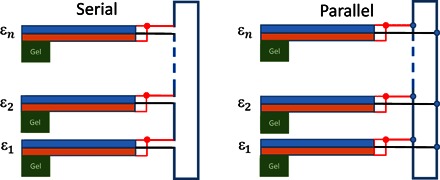
ε1, ε2, …, εn are the force polarities of the n connected units. The orange and blue rectangles depict the two layers of a bimorph PZ plate. The green rectangles depict the self-oscillating BZ gels. The red and black lines show the electrical connections to the respective external and internal electrodes in the PZ plates.
RESULTS
Theoretical modeling
The dynamic behavior of the BZ-PZ circuits (such as those in Figs. 1 and 2) can be captured by coupling the equations for the volumetric oscillations of the BZ gels to the equations for the bending elasticity of PZ beams (5). Each BZ gel is assumed to be immersed in a solution of BZ reactants under conditions required for the autonomous chemomechanical oscillations of the gel. Notably, millimeter-sized pieces of the gel can pulsate autonomously for hours (8). We emphasize that the chemical energy from the BZ reaction provides the external power source in this system. Namely, this energy powers the mechanical oscillations of the gel that, in turn, prompt the deflection of the PZ cantilever, which generates the electrical voltage. This process does not occur in the absence of the reagents necessary for the BZ reaction (for example, the chemicals in the solution and the catalyst in the gel). Moreover, the process will stop when the reagents are consumed. However, the system can be resuscitated by adding more BZ reagents to the solution (8). The gel size is taken to be sufficiently small that the diffusion of dissolved reactants throughout the gel occurs faster than variations of the reactant concentrations in the course of the oscillatory BZ reaction. We used a modification of the Oregonator model to describe the kinetics of the BZ reaction in terms of the concentrations of activator, u, oxidized catalyst, v, and volume fraction of polymer, φ (see the Supplementary Materials) (9, 10). In a system that consists of n units, the reaction kinetics for the BZ gel in each unit is given by (11, 12)
| (1) |
| (2) |
where i = 1, 2, …, n labels the units, and FBZ and GBZ are the reaction rates that depend on the concentrations ui, vi, and volume fraction of polymer φi (see the Supplementary Materials).
In a BZ gel, periodic variations in the concentration of oxidized catalyst, v, due to the BZ reaction affect the polymer-solvent interactions and drive the gel’s rhythmic expansion and contraction. Because small gels equilibrate in size faster than the time scale for one oscillation of the BZ reaction, a gel’s dimensions are determined by a balance among the elasticity of the network, osmotic pressure of the polymer, and force exerted by the cantilever; this balance is expressed as follows (5, 13)
| (3) |
The first term on the left-hand side of Eq. 3 is the elastic stress within the gel that is proportional to the gel cross-link density, c0, and depends on the gel’s degrees of swelling in the longitudinal, λi, and transverse, λ⊥, directions. The volume fraction of polymer is calculated as , where φ0 is the polymer volume fraction in the undeformed gel. The second term in the left-hand side of Eq. 3 is the pressure exerted on the gel by the cantilever, where and h0 are the compression force acting on the gel and the size of the undeformed gel cube, respectively. For simplicity, in Eq. 3, we assumed that the gel deformations are uniaxial, and thus, λ⊥ is set to a constant value. Finally, the right-hand side of Eq. 3 provides the osmotic pressure of the polymer that includes the contributions according to the Flory-Huggins theory, πFH, and due to the hydrating effect of the oxidized catalyst (see the Supplementary Materials). The strength of the hydrating effect is controlled by the interaction parameter χ∗.
The behavior of the PZ cantilevers can be described by quasi-static equations because the frequency of the chemomechanical oscillations (~ 10−2 Hz) is much lower than the eigenfrequency of a cantilever (~ 104 Hz). Applied to the cantilever in the unit i, these equations provide the deflection, ξi, and the electric charge, 𝒬Qi, of the PZ plate as linear functions of the bending force, Fi, exerted on the cantilever and the electric potential difference (voltage), Ui, between the electrodes (see Fig. 1) (14)
| (4) |
| (5) |
The coefficients m11, m12, and m22 depend on the cantilever dimensions, the material properties of the PZ, and the structure of the plate (see the Supplementary Materials). The cantilevers are considered to have a parallel bimorph structure, that is, they consist of two identical layers of a polarized PZ material with the internal and external surface electrodes connected in parallel (see Fig. 1). The cantilevers are taken to be sufficiently thin that they are deflected by the relatively soft, expanding gels (5).
The vector of polarization in the PZ bending plates is oriented perpendicular to the plate surface. The polarity of the voltage generated by the bending of the plate depends therefore on the mutual orientation of the vector of polarization and the bending force applied to the cantilever’s tip in the direction normal to the surface. Equations 4 and 5 capture the latter effect through the force polarity εi, which has a binary value: it is equal to +1 if the direction of the vector of polarization coincides with that of the applied force, or −1 if the polarization and force are in opposite directions.
Within a BZ-PZ unit, the chemomechanical oscillations in the BZ gel (Eqs. 1 to 3) and bending of the PZ cantilever (Eqs. 4 and 5) are coupled through the forces and displacements because and ξi = (λi − λ∗) h0, where λ∗h0 is the spatial offset between the gel and cantilever. In an isolated unit, the force acting on the gel depends only on the size of this gel, λi. It is assumed that the cantilever remains in contact with the gel throughout the entire cycle of gel swelling and deswelling so that ξi ≥ 0 in an isolated unit. Wiring multiple BZ-PZ units into a network leads to interactions among all the PZ cantilevers, and hence, the force acting on a given gel depends on the degrees of swelling (sizes) of all the gels in the system.
We assume that the connected units are identical and differ only in their force polarity. Then, the interaction between the BZ-PZ units depends only on the network topology. The strength of interaction can be determined by using Eqs. 4 and 5, as demonstrated by Yashin et al. (5) for the serial and parallel circuits in Fig. 2.
Given that Ui is the voltage across the ith unit, then for units connected in series, the sum of the voltages over all n units is equal to zero, that is, . In addition, for the serial connection, the charge on each unit is equal to the total charge in the system, that is, Qi = Q. With these relationships, we calculate that the bending force acting on the cantilever i can be written as
| (6) |
Here, is Hook’s law for a bending elastic plate, and is the coupling strength coefficient, which is small and depends only on material properties of the cantilevers (5).
For units connected in parallel, the system obeys the following constraints: Ui = U and . In this case, the bending force acting on each cantilever is
| (7) |
Equations 6 and 7 show that the bending force on a given cantilever contains contributions from all BZ-PZ units in the network. The cross terms on the right-hand sides of Eqs. 6 and 7 correspond to pairwise interactions, which depend on the force polarities, and are relatively weak because κ is small. The pairwise interactions in the serial and parallel circuits have the same magnitudes but are opposite in signs.
We previously observed that these coupled BZ-PZ oscillator networks can achieve both in-phase and antiphase synchronization, depending on the initial phases, connection type, and force polarity of each oscillator unit (5). By specifying these conditions, the network can exhibit particular modes of synchronization. Below, we discuss how the synchronization dynamics in the BZ-PZ could be used for pattern recognition tasks.
Pattern recognition with BZ-PZ oscillator networks
A number of schemes have been proposed for using networks of oscillators for pattern recognition tasks (2, 15–17). Of particular relevance to our studies is the oscillatory neural network (ONN) model (2), which has been implemented using electrical phase-locked loop circuits and microelectromechanical systems (3, 4). This model for a dynamical system yielded attractor basins at the minima of an appropriate energy function (that is, Lyapunov energy function) that could be obtained by adjusting the coupling parameters, through specified rules for updating the neural network (18). The networks described by this model can be used to store patterns that are represented by phase differences between the oscillators and to perform the functions of an associative memory (2). Specifically, an input pattern drives the dynamics of the network toward some modes of synchronization among the oscillators, and convergence to a particular mode constitutes recognition of a specific pattern from a set of stored patterns.
Inspired by the ONN model, we propose a similar computing paradigm for networks of coupled BZ-PZ oscillators. We specifically focus on BZ-PZ oscillators that are connected in series. Figure 3 illustrates how we transcribe a black-and-white image into this serially connected network. Each oscillator unit represents one pixel of the image, and we specify the polarity of the PZ cantilever in each unit according to the color of the image. In particular, we assign the polarity the value of +1 for a white pixel and −1 for a black pixel. Rastering through the n pixels in the image (going from left to right), we assign a value of the polarity to each of the n oscillators according to the color of the pixel. In the device, the desired force polarities can be achieved by flipping the connecting wires; this changes the sign of the voltage generated by a BZ-PZ unit.
Fig. 3. Schematics indicating how to transpose a black-and-white image onto the serially connected network of the BZ-PZ oscillators.
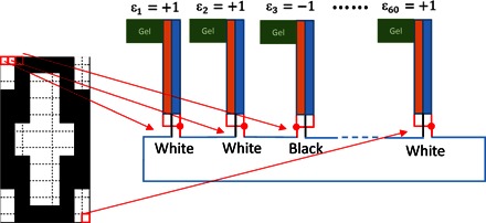
Here, we store a binary image of the digit “0” that contains 60 pixels. The force polarity of an oscillator is set to +1 for a white pixel and to −1 for a black pixel. The coloring in the BZ-PZ units is the same as in Fig. 2. Note that assigning ε3 = −1 is achieved through flipping the red and black connector wires.
Our rationale for the above procedure is based on our findings for the synchronization of three BZ-PZ oscillators connected in series (5). For a serial circuit of three oscillators having different force polarities, for example, {+1 , +1, −1}, the only stable mode of synchronization corresponds to the in-phase synchronization (no phase difference) of the +1 units, which, in turn, are synchronized antiphase (phase difference 0.5) with the −1 unit. Note that all phases are normalized to vary between 0 and 1. On the basis of extensive numerical simulations and a linear stability analysis (see the Supplementary Materials), we conjecture that multiple BZ-PZ units connected in series exhibit a stable synchronization mode characterized by the in-phase synchronization of all the oscillators that have the same polarity and the antiphase synchronization with oscillators of different polarity.
There is an important difference between the ONN model and the BZ-PZ network shown in Fig. 3. Namely, in the ONN model, the coupling weights of oscillators are real numbers assigned according to the Hebbian learning rule that makes storing multiple patterns possible (19). In contrast, the force polarity factors in our oscillator network can only be a binary value, +1 or −1, so that each oscillator network is expected to store a single pattern. Hence, in this work, we define the pattern recognition task as retrieving one pattern that is closest to the pattern stored in the system from multiple input patterns.
To initiate the recognition process, we use an input pattern to initialize the phase ϕ of each oscillator in the network, with ϕ = 0 for a black pixel and ϕ = 0.5 for a white pixel (see Fig. 4). Notably, the dynamics of the BZ gels are chemo-, photo-, and mechanoresponsive (13, 20), and hence, the initial variations in phase among the units can be introduced by local applications of chemical stimulation, light, or pressure.
Fig. 4. Illustration of the pattern recognition task.
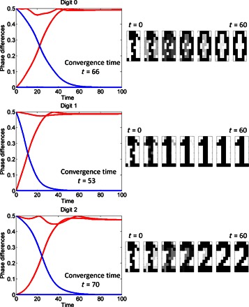
The three different BZ-PZ oscillator networks, which store the respective images for the digits “0,” “1,” and “2,” are initialized with the same distorted “1” input image. The phase differences of the oscillations in the networks converge to the respective stored patterns in the course of synchronization. The blue and red lines distinguish between the two groups of oscillators that converge to the phase difference of 0 and 0.5, respectively. The convergence is the fastest in the network exhibiting the best match between the input and stored patterns, that is, in the network that stores the digit “1.”
After the initialization, the system evolves the phases into some stable state, transforming the input pattern to some other pattern. As detailed below, our simulations reveal that an input pattern evolves to the stored pattern, which is defined by the set of force polarities. The rate of convergence of the input image to the stored image depends on the similarity between the two images. “Convergence” means that the oscillators representing the black pixels in the stored pattern establish the in-phase synchronization among themselves, and the antiphase synchronization with the oscillators that represent the white pixels. As detailed in the Supplementary Materials, we confirm the stability of the state of synchronization imposed by the stored pattern by using a linear stability analysis.
Figure 4 illustrates the pattern recognition task performed by three different BZ-PZ oscillator networks, which store the respective images for the digits “0,” “1,” and “2.” The networks are simultaneously initialized with the same distorted “1” test image. Namely, the test image is used to set the initial phases of the pixels, as noted above. In the panels on the left, we show the temporal evolution in the systems by plotting the phase differences between the first oscillator and all the other oscillators (in the given system) as a function of time. The phase differences are plotted in the range from 0 to 0.5, which correspond to the in-phase and antiphase synchronization, respectively (see the Supplementary Materials). In the panels on the right, the first image represents the initial input pattern, and the temporal evolution of the networks is displayed through a sequence of images for the first 60 units of time; the interval between the images is equal to 10 time units. The unit of time is κ−1T0 ~ 5 min, where κ ≈ 0.2 is the strength of coupling (see Eq. 6) and T0 ~ 1 min is the period of oscillation of the uncoupled oscillators. Figure 4 reveals two important results. First, all these three networks converge to their own stored patterns. Second, the network that stores the number “1” converges faster than the other two systems. That is, the network storing the image “1” provides the best match between the input and stored patterns and, hence, is the “winner” in the recognition task.
The results shown in Fig. 4 suggest that the convergence time can serve as a degree of match (DoM) that measures the differences between the input pattern and each stored pattern. Hence, a system consisting of multiple BZ-PZ oscillator networks can recognize patterns by detecting the shortest convergence time among the networks (15, 21). To support this hypothesis, we conducted multiple computational tests discussed in the next section.
As noted above, the initial input patterns can be introduced into the network by setting the phases of oscillation in the individual BZ gels through chemical, optical, or mechanical techniques (20). Another method for storing patterns is to take advantage of the coupled oscillator network dynamics. Because each oscillator network evidently converges to the pattern set by the force polarities, we can set the oscillator force polarities with the input pattern vectors in the same way as we set the stored patterns. Once the network phases become stable to the phases corresponding to the input test pattern, we switch the force polarities to the stored pattern and then measure the convergence time to this stored pattern.
DISCUSSION
Robustness of the pattern recognition
Here, we discuss various computer simulations designed to analyze synchronization of coupled BZ-PZ oscillators connected in series, and demonstrate that the convergence time of coupled oscillator networks does indeed provide a robust measure of pattern recognition.
We conduct the following three sets of computer simulations focused on measuring and comparing the convergence times obtained with different test patterns and stored patterns. First, we explore how the convergence time of a network is related to the difference between the input pattern and the stored pattern (test 1). Second, we test the capability of two independent networks to discriminate between two stored patterns with the “cross-pattern” test (test 2). Finally, we apply the coupled oscillator network to the recognition task for images of the digits “0” to “9” and analyze the recognition performance and robustness (test 3).
For all these tests, we define the convergence time of synchronization as the number of time units, κ−1T0, needed for the coupled oscillators to reach the stable state of synchronization that represents the stored pattern. Specifically, in this stable state, the phase difference values of oscillators are separated into two groups representing the black and white pixels, with each oscillator’s phase being within 1% of the group average.
In test 1, we initially demonstrate that the time for convergence depends on the similarity between the stored and input patterns. For this purpose, we compare the convergence time to the Hamming distance, which is the sum of the element-wise differences between two binary vectors. This parameter is a quantitative measure of the total difference between given images of the same size. Note that the phase dynamics and synchronization mode for the mirror (bit complement) pattern are indistinguishable from those for the original pattern; this can be seen from Eqs. 6 and 8, where the right-hand side of the equation does not change when the signs of all the force polarities are altered simultaneously. Therefore, we effectively consider a stored pattern and its mirror pattern in a single network.
To vary the Hamming distance between a given stored pattern and an input, we start with the copy of the stored pattern and generate input patterns by flipping an increasing number of pixels until the input pattern is transformed into the mirror pattern. In this procedure, the input patterns are gradually less similar to the stored pattern and more similar to the mirror pattern, as illustrated in Fig. 5. For the stored pattern shown in Fig. 5, the Hamming distance between the stored and mirror patterns is 99. The Hamming distance between the input pattern and one of the stable states of the system changes consecutively as 1, 2,…, 49, 50, 49,…, 2, 1.
Fig. 5. The stored 10 × 10 pattern and an example of the input pattern set used in test 1.
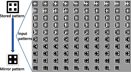
The set is generated by flipping an increasing number of pixels until the input pattern is transformed into the mirror pattern. The difference between the stored pattern and an image from the set is characterized by the Hamming distance, which is the sum of the element-wise differences between two binary vectors.
The images in Fig. 5 represent only one particular sequence of input patterns characterized by the above set of Hamming distances to the stable states. In test 1, for a given Hamming distance, the bits to be flipped are selected randomly, and the convergence time is averaged over 100 runs, so that 99 × 100 input patterns were tested for convergence. The comparison between the obtained convergence time and Hamming distance is shown in Fig. 6. Figure 6 indicates that the time for the coupled oscillator network to synchronize follows the trend of the difference between input and stored patterns so that the convergence time decreases with a decrease in the Hamming distance. (The convergence time decreases after 50 bits have been flipped because, as noted above, the phase dynamics and synchronization mode for the mirror and stored patterns are indistinguishable.) That is, the convergence time provides a robust measure of the DoM between the input and stored patterns.
Fig. 6. The average convergence time obtained in test 1 (blue line) and the Hamming distance between the stored and input images (orange line) as functions of the number of flipped bits.
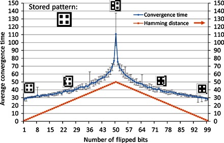
The error bars show the range of convergence times obtained from 100 runs at a given number of flipped bits, which were selected at random from all the bits in the system.
In the cross-pattern simulations, test 2, we explore the ability of our system to discriminate between two distinct patterns. In this test, we choose the two patterns, p1 and p2 shown in Fig. 7, and store them in two oscillator networks. They share some bit values at certain pixel positions and differ at the others. We label p0 as the set of pixels where p1 and p2 share the same values, and px as the set of pixels where they differ from each other. To generate the input patterns, we use the same strategy of flipping bits as in test 1. Specifically, we select pixel positions from px and set them to the value in p2 so that the input pattern gradually evolves from p1 to p2. As in test 1, for each number of pixels, the random selection is repeated 100 times.
Fig. 7. An example of the 10 × 10 stored and input patterns used in test 2.
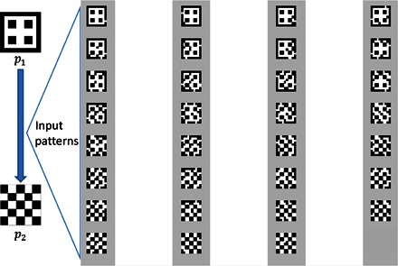
The input patterns are generated using the same strategy of flipping bits as in test 1.
Every input pattern is applied to both networks (p1 and p2) so that their convergence times can be compared. The number of different bits, the size of px, is 32; thus, we generate 31 sets of input patterns. Figure 8 presents the comparison of convergence times to the stored patterns p1 and p2. As the input patterns evolve from p1 to p2, the convergence time to p1 increases, whereas the convergence time to p2 decreases. The results indicate that we can use the convergence time to determine which stored pattern is close to the input pattern. It is only when the input pattern is equally similar to both stored patterns (within a few bits) that the system fails to identify which one is closer.
Fig. 8. The average times of convergence to the stored patterns p1 (blue line) and p2 (orange line) obtained in test 2 as functions of the number of flipped bits.
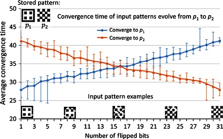
The error bars are obtained as described in Fig. 6.
In the cross-pattern test shown in Fig. 8, the size of px is less than half of the total number of pixels in the image. If we select p1 and p2 with a larger value of px, the two stored patterns become more similar to each other’s mirror pattern, and the convergence time should be affected. To demonstrate this point, we perform the cross-pattern test on two different stored patterns where the size of px = 64. Figure 9 shows the images of the two chosen patterns, and the convergence times to both p1 and p2 as functions of the number of flipped bits. The latter plot reveals that as the pattern distances continue to increase, the curves are no longer monotonic. The reason for this behavior is due to the presence of the mirror pattern in each network. For example, the convergence time to p1 increases monotonically as the input patterns become less similar to p1. However, because the size of px is large, after 45 pixels have been flipped, the input patterns become increasingly similar to the mirror pattern of p1. Therefore, these input patterns actually converge to the mirror pattern of p1; this behavior was also observed in Fig. 6, the result of test 1. However, even with the interference of the mirror patterns, the two stored patterns can be distinguished from each other because the convergence times are distinct for the two samples, except at a few points (between 30 and 32 flips on the x axis).
Fig. 9. The average times of convergence to the stored patterns p1 (blue line) and p2 (orange line) obtained in test 2 as functions of the number of flipped bits.
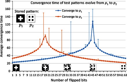
The two stored patterns are more similar to each other’s mirror patterns than the stored patterns in Fig. 8. The observed peaks are similar to the one in Fig. 6, the result of test 1.
Finally, in test 3, we examine the performance of our coupled oscillator network on a pattern recognition task that is expanded from the one shown in Fig. 4. Now, the stored patterns are 60-pixel binary images of digits “0” to “9” (see Fig. 10). The input patterns are distorted images of each digit, with noise that is generated by randomly flipping bits. The degree of added noise gradually increases in the recognition tests, as 1, 5, 10, 15, 20, 25, and then 30 pixels are randomly selected and flipped from the original digit images; here, we perform 100 simulations for each case. Figure 10 not only shows the stored patterns but also provides examples of the input patterns for distorted images of digits “3” (Fig. 10B) and “8” (Fig. 10C). In each convergence simulation, we impose an input pattern onto 10 networks of 60 coupled oscillators; each network stores one image of a digit. A network recognizes the input pattern yielding the shortest convergence time, which corresponds to the highest DoM. If the winner is the same digit as the original digit of the noisy input pattern, the recognition is a hit; otherwise, it is a miss.
Fig. 10. The images used in test 3.
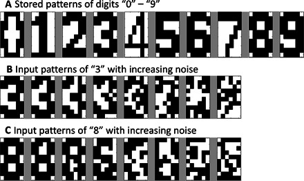
(A) Binary images (10 × 6) of the 10 digits used as the stored patterns. (B and C) Distorted images of the digits “3” and “8” that are obtained by flipping 1, 5, 10, 15, 20, 25, and 30 pixels that are randomly selected.
Figure 11 is a bar graph of the recognition accuracy for the cases of stored digit patterns “1,” “3,” “5,” and “7.” As the noise increases, the recognition accuracies decrease. The cases of 30 flipped bits are not shown because when half of the bits are flipped, the recognition accuracies drop to zero. The reason for the latter behavior is that the input patterns for these cases are actually further from the original digit pattern than they are from the others. Among the four patterns shown here, “3” produces the worst recognition performance because this digitized image is very close to “6,” “8,” and “9” with very few different pixels (see Fig. 10). The performance data for the full test can be found in the Supplementary Materials.
Fig. 11. The accuracies of the recognition test 3 for the input patterns of the digits “1,” “3,” “5,” and “7” that are distorted with various levels of noise.
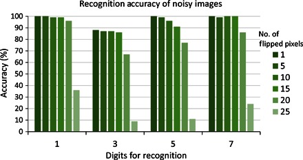
The bars are colored according to the noise level. The horizontal axis indicates the input patterns.
Further, each column in Fig. 12 represents the difference between the convergence times for the winner and the runner-up for all the hit cases. The height of the column is a measure of the robustness of the recognition task; the data are plotted for the different degrees of noise. The results indicate that when the degree of noise is increased, the time lag between the runner-up and the winner becomes shorter and, hence, it becomes more difficult for the oscillator system to differentiate the correct pattern in an efficient manner.
Fig. 12. The difference between the average convergence times of the winner and of the runner-up in all the hit cases in test 3 for the digits shown in Fig. 11.
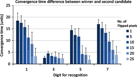
The error bars show the SD obtained for each bar. The results indicate how fast the correct, recognized winner leads the runner-up. The other notations are the same as in Fig. 11.
In summary, we designed a materials system that can sense, actuate, communicate, and compute in a self-organized manner. This functionality is enabled by the unique properties of the BZ gels, which do not require external power sources to drive their oscillatory motion. [As indicated above, the gels can continue to oscillate with the addition of reagents when these chemicals are consumed (8).] Moreover, these BZ gels are responsive to mechanical input from the overlying PZ materials. The PZs also play a crucial and distinctive role through their interconversion of mechanical and electrical energy, where the deformation of the cantilevers provides the voltage that flows through the system. We then used these hybrid gel-PZ units to couple local chemomechanical oscillations over long distances through electrical connections. This coupling allowed the oscillations of BZ-PZ units to become synchronized; in a network where the units are connected in series, the units with the same force polarity are synchronized in-phase and the ones with opposite force polarities are synchronized out-of-phase. Taking advantage of the distinct synchronization behavior of these chemomechanical networks, we leveraged concepts from oscillator-based computing to use our coupled BZ-PZ oscillators in performing pattern recognition tasks. In particular, we imposed a collection of input patterns onto different BZ-PZ networks, where each network encompassed a distinct stored pattern. The network encompassing the stored pattern closest to the input pattern exhibited the fastest convergence time to stable synchronization behavior and could be identified as the winner. In this way, the networks of coupled BZ-PZ oscillators achieved pattern recognition. We demonstrated that the convergence time to stable synchronization provides a robust measure of the DoM between the input and stored patterns. Through these studies, we laid out fundamental and experimentally realizable design rules for creating materials that compute.
MATERIALS AND METHODS
Phase dynamics
To facilitate our investigation of synchronization in the BZ-PZ oscillator networks, we used the phase dynamics approach developed for weakly coupled oscillators (22, 23). This technique allows us to significantly simplify the analysis of the dynamics of the oscillator networks because the interaction between weakly coupled oscillators only results in the time-dependent deviation of phase in each oscillator. If known, the function that describes the oscillator phase response can be used to simulate a coupled oscillator system in the phase domain and thus reduce the complexity of the simulation as compared to the original nonlinear oscillator equations (Eqs. 1 to 5). For networks of identical BZ-PZ oscillators, this function was numerically determined by Yashin et al. (5). It was shown that the phase dynamics in the serially connected network (see Fig. 2 and Eq. 6) is described by the following equation
| (8) |
For the parallel connection (see Fig. 2 and Eq. 7), the phase dynamics equation is
| (9) |
The oscillation phase normalization in Eqs. 8 and 9 is such that 0 ≤ ϕi ≤ 1 and i = 1, 2, …, n. The function H(ϕj − ϕi) (connection function) characterizes the rate of the phase shift for the oscillator i due to the interaction with the oscillator j at their relative phase difference of ϕj − ϕi. The connection function H(θ) is periodic at θ ∈ [0, 1] and determined by the intrinsic properties of the oscillators described by Eqs. 1 to 3.
Figure 13 shows the plot of the connection function obtained by Yashin et al. (5). It is evident that the phase response of a BZ-PZ oscillator to an external action is quite complicated. The interaction between the oscillators can cause both positive and negative phase shifts depending on the phase difference, and this results in a variety of stable phase synchronization modes exhibited by the BZ-PZ oscillator networks (5). For any set of initial phases for the individual oscillators, the system dynamics converge to one of the stable synchronization modes.
Fig. 13. The connection function H(θ) used in the equations of the phase dynamics (Eqs. 8 and 9).
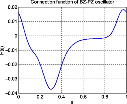
The connection function is periodic at θ ∈ [0, 1].
Materials
The connection function H(θ) shown in Fig. 13 was numerically obtained by Yashin et al. (5) for the set of materials and model parameters specified below (see the Supplementary Materials for more details). We assumed that the BZ gel is formed from poly(N-isopropylacrylamide) (PNIPAAm) chains containing grafted ruthenium metal-ion catalysts (7). The model parameters are the same as in the study by Yashin et al. (5). The volume fraction of polymer and the cross-link density in the undeformed BZ gel are φ0 = 0.16 and c0 = 4 × 10⁻⁴, respectively. The interaction parameter χ∗, which accounts for the hydrating effect of the oxidized catalyst, is χ∗ = 0.105. The undeformed gel size is h0 = 0.5 mm. The values of λ⊥ and of the offset λ∗ are λ⊥ = λ∗ ≈ 1.65, which corresponds to the steady-state value for the isotropic (unrestricted) swelling of the BZ gel (5).
The cantilever was assumed to be fabricated from polarized lead zirconate titanate (PZT) ceramics, one of the most commonly used PZs (24). The length and width of the PZ bimorph plate are 1 mm, and the layer thickness is 10 μm. We assumed that the PZ cantilevers are fabricated using advanced processing methods (25, 26), which yield a twofold increase in the PZ constant relative to a typical PZT. At the model parameter values used for the calculations, the strength of coupling is κ ≈ 0.206. For the chosen model parameters, the period of oscillation of the uncoupled oscillators is T0 ~ 1 min (5).
Feasibility of fabricating the system
Recent advances in the fabrication of hybrid gel-PZ systems indicate the feasibility of creating the BZ-PZ oscillator networks described here. In particular, studies have demonstrated that the deformation of a humidity-responsive polymer network on a PZ film could generate measurable voltages (27). It has also been shown that arrays of millimeter-sized PZ actuator-sensor systems, which are laminated on soft biological materials, could monitor the mechanical properties of the underlying material (28). Hence, current state-of-the-art manufacturing techniques allow researchers to fabricate millimeter-sized gel-PZ elements, which generate strong electric signals.
Supplementary Material
Acknowledgments
We thank S. J. Dickerson for helpful discussion. Funding: This work was supported by NSF grant DMR-1344178. Author contributions: S.P.L. and A.C.B. conceived the idea and supervised the work. Y.F. and V.V.Y. performed theoretical analysis and numerical simulations. Competing interests: The authors declare that they have no competing interests. Data and materials availability: All data needed to evaluate the conclusions in the paper are present in the paper and/or the Supplementary Materials. Additional data related to this paper may be requested from the authors.
SUPPLEMENTARY MATERIALS
Supplementary material for this article is available at http://advances.sciencemag.org/cgi/content/full/2/9/e1601114/DC1
Kinetics of the BZ reaction in a polymer gel.
Osmotic pressure of the polymer in a gel.
Properties of a bending PZ bimorph plate.
Procedure used to map phase dynamics to 0 ≤ ϕ ≤ 0.5.
Stability of the synchronization mode.
Complete set of results for test 3.
The effect of gel heterogeneities on synchronization.
fig. S1. The phase differences plotted in the ranges [0, 1] and [0, 0.5].
fig. S2. The phase difference ψ between the two groups of oscillators.
fig. S3. The accuracies of the recognition test 3 for the input patterns of all 10 digits distorted with various levels of noise.
fig. S4. The height of the bars represents the average convergence time difference between the winner and the runner-up in all the hit cases in test 3.
fig. S5. The accuracy in recognizing the digit “7” as a function of the number of flipped pixels in the case where 60 pixels are used to represent the digit.
fig. S6. The phase dynamics for the uniform distribution ΔT/T0 ∈ [−σ, σ] for various values of σ.
fig. S7. The convergence time at random ΔT/T0 ∈ [−σ, σ] as a function of the distribution width σ.
REFERENCES AND NOTES
- 1.Stuart M. A. C., Huck W. T. S., Genzer J., Müller M., Ober C., Stamm M., Sukhorukov G. B., Szleifer I., Tsukruk V. V., Urban M., Winnik F., Zauscher S., Luzinov I., Minko S., Emerging applications of stimuli-responsive polymer materials. Nat. Mater. 9, 101–113 (2010). [DOI] [PubMed] [Google Scholar]
- 2.Hoppensteadt F. C., Izhikevich E. M., Oscillatory neurocomputers with dynamic connectivity. Phys. Rev. Lett. 82, 2983–2986 (1999). [Google Scholar]
- 3.Hoppensteadt F. C., Izhikevich E. M., Pattern recognition via synchronization in phase-locked loop neural networks. IEEE Trans. Neural Netw. 11, 734–738 (2000). [DOI] [PubMed] [Google Scholar]
- 4.Hoppensteadt F. C., Izhikevich E. M., Synchronization of MEMS resonators and mechanical neurocomputing. IEEE Trans. Circuits Syst. I Reg. Papers 48, 133–138 (2001). [Google Scholar]
- 5.Yashin V. V., Levitan S. P., Balazs A. C., Achieving synchronization with active hybrid materials: Coupling self-oscillating gels and piezoelectric films. Sci. Rep. 5, 11577 (2015). [DOI] [PMC free article] [PubMed] [Google Scholar]
- 6.McEvoy M. A., Correll N., Materials that couple sensing, actuation, computation, and communication. Science 347, 1261689 (2015). [DOI] [PubMed] [Google Scholar]
- 7.Yoshida R., Takahashi T., Yamaguchi T., Ichijo H., Self-oscillating gel. J. Am. Chem. Soc. 118, 5134–5135 (1996). [Google Scholar]
- 8.Chen I. C., Kuksenok O., Yashin V. V., Balazs A. C., Van Vliet K. J., Mechanical resuscitation of chemical oscillations in Belousov-Zhabotinsky gels. Adv. Funct. Mater. 22, 2535–2541 (2012). [Google Scholar]
- 9.Yashin V. V., Kuksenok O., Balazs A. C., Computational design of active, self-reinforcing gels. J. Phys. Chem. B 114, 6316–6322 (2010). [DOI] [PubMed] [Google Scholar]
- 10.Yashin V. V., Suzuki S., Yoshida R., Balazs A. C., Controlling the dynamic behavior of heterogeneous self-oscillating gels. J. Mater. Chem. 22, 13625–13636 (2012). [Google Scholar]
- 11.Yashin V. V., Balazs A. C., Modeling polymer gels exhibiting self-oscillations due to the Belousov-Zhabotinsky reaction. Macromolecules 39, 2024–2026 (2006). [Google Scholar]
- 12.Yashin V. V., Balazs A. C., Theoretical and computational modeling of self-oscillating polymer gels. J. Chem. Phys. 126, 124707 (2007). [DOI] [PubMed] [Google Scholar]
- 13.Yashin V. V., Levitan S. P., Balazs A. C., Modeling the entrainment of self-oscillating gels to periodic mechanical deformation. Chaos 25, 064302 (2015). [DOI] [PubMed] [Google Scholar]
- 14.R. G. Ballas, Piezoelectric Multilayer Beam Bending Actuators: Static and Dynamic Behavior and Aspects of Sensor Integration (Springer, New York, 2007). [Google Scholar]
- 15.Fang Y., Gnegy C. N., Shitbata T., Dash D., Chiarulli D. M., Levitan S. P., Non-Boolean associative processing: Circuits, system architecture, and algorithms. IEEE J. Explor. Solid State Comput. Devices Circuits 1, 95–103 (2015). [Google Scholar]
- 16.Nikonov D. E., Csaba G., Porod W., Shibata T., Voils D., Hammerstrom D., Young I. A., Bourianoff G. I., Coupled-oscillator associative memory array operation for pattern recognition. IEEE J. Explor. Solid State Comput. Devices Circuits 1, 85–93 (2015). [Google Scholar]
- 17.Maffezzoni P., Bahr B., Zhang Z., Daniel L., Oscillator array models for associative memory and pattern recognition. IEEE Trans. Circuits Syst. I Reg. Papers 62, 1591–1598 (2015). [Google Scholar]
- 18.Izhikevich E. M., Weakly pulse-coupled oscillators, FM interactions, synchronization, and oscillatory associative memory. IEEE Trans. Neural Netw. 10, 508–526 (1999). [DOI] [PubMed] [Google Scholar]
- 19.Hopfield J. J., Neural networks and physical systems with emergent collective computational abilities, Proc. Natl. Acad. Sci. U.S.A. 79, 2554–2558 (1982). [DOI] [PMC free article] [PubMed] [Google Scholar]
- 20.Yashin V. V., Kuksenok O., Dayal P., Balazs A. C., Mechano-chemical oscillations and waves in reactive gels. Rep. Prog. Phys. 75, 066601 (2012). [DOI] [PubMed] [Google Scholar]
- 21.T. Shibata, R. Zhang, S. P. Levitan, D. E. Nikonov, G. I. Bourianoff, CMOS supporting circuitries for nano-oscillator-based associative memories, in Proceedings of the 13th International Workshop on Cellular Nanoscale Networks and Their Applications, Turin, Italy, 29 to 31 August 2012 (IEEE, Piscataway, NJ, 2012). [Google Scholar]
- 22.F. C. Hoppensteadt, E. M. Izhikevich, Weakly Connected Neural Networks (Springer, New York, 2007). [Google Scholar]
- 23.E. M. Izhikevich, Dynamical Systems in Neuroscience: The Geometry of Excitability and Bursting (MIT Press, Cambridge, 2007), chap. 10. [Google Scholar]
- 24.A. Preumont, Mechatronics: Dynamics of Electromechanical and Piezoelectric Systems (Springer, Dordrecht, 2006). [Google Scholar]
- 25.Baek S. H., Park J., Kim D. M., Aksyuk V. A., Das R. R., Bu S. D., Felker D. A., Lettieri J., Vaithyanathan V., Bharadwaja S. S. N., Bassiri-Gharb N., Chen Y. B., Sun H. P., Folkman C. M., Jang H. W., Kreft D. J., Streiffer S. K., Ramesh R., Pan X. Q., Trolier-McKinstry S., Schlom D. G., Rzchowski M. S., Blick R. H., Eom C. B., Giant piezoelectricity on Si for hyperactive MEMS. Science 334, 958–961 (2011). [DOI] [PubMed] [Google Scholar]
- 26.Baek S.-H., Rzchowski M. S., Aksyuk V. A., Giant piezoelectricity in PMN-PT thin films: Beyond PZT. MRS Bull. 37, 1022–1029 (2012). [Google Scholar]
- 27.Ma M., Guo L., Anderson D. G., Langer R., Bio-inspired polymer composite actuator and generator driven by water gradients. Science 339, 186–189 (2013). [DOI] [PMC free article] [PubMed] [Google Scholar]
- 28.Dagdeviren C., Shi Y., Joe P., Ghaffari R., Balooch G., Usgaonkar K., Gur O., Tran P. L., Crosby J. R., Meyer M., Su Y., Webb R. C., Tedesco A. S., Slepian M. J., Huang Y., Rogers J. A., Conformal piezoelectric systems for clinical and experimental characterization of soft tissue biomechanics. Nat. Mater. 14, 728–736 (2015). [DOI] [PubMed] [Google Scholar]
- 29.Tyson J. J., Fife P. C., Target patterns in a realistic model of the Belousov–Zhabotinskii reaction. J. Chem. Phys. 73, 2224–2237 (1980). [Google Scholar]
- 30.Hirotsu S., Softening of bulk modulus and negative Poisson’s ratio near the volume phase transition of polymer gels. J. Chem. Phys. 94, 3949–3957 (1991). [Google Scholar]
- 31.P. J. Davis, Circulant Matrices (Chelsea, New York, 1994). [Google Scholar]
Associated Data
This section collects any data citations, data availability statements, or supplementary materials included in this article.
Supplementary Materials
Supplementary material for this article is available at http://advances.sciencemag.org/cgi/content/full/2/9/e1601114/DC1
Kinetics of the BZ reaction in a polymer gel.
Osmotic pressure of the polymer in a gel.
Properties of a bending PZ bimorph plate.
Procedure used to map phase dynamics to 0 ≤ ϕ ≤ 0.5.
Stability of the synchronization mode.
Complete set of results for test 3.
The effect of gel heterogeneities on synchronization.
fig. S1. The phase differences plotted in the ranges [0, 1] and [0, 0.5].
fig. S2. The phase difference ψ between the two groups of oscillators.
fig. S3. The accuracies of the recognition test 3 for the input patterns of all 10 digits distorted with various levels of noise.
fig. S4. The height of the bars represents the average convergence time difference between the winner and the runner-up in all the hit cases in test 3.
fig. S5. The accuracy in recognizing the digit “7” as a function of the number of flipped pixels in the case where 60 pixels are used to represent the digit.
fig. S6. The phase dynamics for the uniform distribution ΔT/T0 ∈ [−σ, σ] for various values of σ.
fig. S7. The convergence time at random ΔT/T0 ∈ [−σ, σ] as a function of the distribution width σ.


