

Abstract
Cilia and flagella are highly conserved organelles that beat rhythmically with propulsive, oscillatory waveforms. The mechanism that produces these autonomous oscillations remains a mystery. It is widely believed that dynein activity must be dynamically regulated (switched on and off, or modulated) on opposite sides of the axoneme to produce oscillations. A variety of regulation mechanisms have been proposed based on feedback from mechanical deformation to dynein force. In this paper, we show that a much simpler interaction between dynein and the passive components of the axoneme can produce coordinated, propulsive oscillations. Steady, distributed axial forces, acting in opposite directions on coupled beams in viscous fluid, lead to dynamic structural instability and oscillatory, wave-like motion. This ‘flutter’ instability is a dynamic analogue to the well-known static instability, buckling. Flutter also occurs in slender beams subjected to tangential axial loads, in aircraft wings exposed to steady air flow and in flexible pipes conveying fluid. By analysis of the flagellar equations of motion and simulation of structural models of flagella, we demonstrate that dynein does not need to switch direction or inactivate to produce autonomous, propulsive oscillations, but must simply pull steadily above a critical threshold force.
Keywords: flagella, dynein, instability, oscillations, cilia
1. Introduction
Flagella and cilia are slender organelles that generate propulsive, oscillatory waveforms (figure 1a) to propel cells or move fluid. The common cytoskeletal structure of cilia and flagella, the ‘9 + 2’ axoneme, consists of nine outer doublet microtubules, a central pair, radial spokes and circumferential links (figure 1b). Dynein molecules form an array of cross-bridges between pairs of microtubule doublets and exert forces that cause sliding of one doublet relative to the other. These active shear forces combine with the forces from passive structural elements (doublets, nexin links and radial spokes) to produce bending [1].
Figure 1.

(a) Schematic diagram of a flagellum with shape parametrized by angle  . (b) Schematic diagram of axial cross section of the flagellar axoneme showing key components; viewed from the distal end, outer doublet microtubules are numbered clockwise from doublet 1.
Since dynein activity on opposite sides of the axoneme produces antagonistic bending forces, it is widely believed that dynein activity must be regulated (switched on and off, or modulated) in order to produce oscillatory waveforms [2–6]. This concept has been supported by a number of theoretical studies that explored the effect of feedback from mechanical deformation to dynein force. In a seminal paper [7], Brokaw showed that delayed feedback from curvature to dynein activity could lead to oscillations. Brokaw has continued to describe and evaluate potential feedback mechanisms in a comprehensive series of modelling papers [8–12]. Hines & Blum [13] developed a detailed mathematical model of flagellar motion in the form of partial differential equations (PDEs); numerical solutions to these equations exhibited sustained, wave-like oscillations when feedback from curvature was included. Murase [14] and Julicher and colleagues [5,15,16] have modelled sliding-controlled, collective dynein behaviour and demonstrated the existence of oscillatory modes in such models. In the ‘geometric clutch’ (GC) hypothesis of dynein regulation proposed by Lindemann [17–19], the spacing between each doublet pair is thought to control the level of dynein cross-linking. In the GC model, dynein activity increases when doublets approach one another and decreases when doublets separate.
Though these feedback models are appealing, experimental evidence that dynein regulation is required for bending oscillations remains circumstantial. For example, Lin et al. [20] has shown by cryo-electron microscopy (cryo-EM) that the dominant conformation of dynein arms (pre-powerstroke or post-powerstroke) differs between adjacent doublet pairs in bent sections of sea urchin flagella. Movassagh et al. [21] also observed that dynein activity was organized into clusters, though no clear relationship was seen between the observed patterns of activity and bending. By analysing waveforms of human sperm flagella, Gaffney et al. [22] and Smith et al. [23] obtained estimates of oscillatory dynein force from estimated viscous and elastic forces. On the other hand, Brokaw [3] has commented that the belief that dynein activity switches ‘on’ and ‘off’ derives mainly from the lack of alternative explanations for oscillation. Intriguingly, Geyer et al. [24] have shown show that gradually increasing dynein activity in reactivated axonemes leads both to (i) a steady increase in static mean curvature and (ii) an abrupt transition to oscillatory beating. These data suggest that simply increasing average dynein activity can lead to instability of the static equilibrium state of the axoneme.
In this study, we show that switching or modulation of dynein activity is not required to generate propulsive, oscillatory waveforms. In an elastic structure submerged in viscous fluid, like the axoneme, steady, distributed axial loading of the doublets (i.e. steady dynein activity) leads to a dynamic structural instability commonly known as flutter. Flutter is a well-known cause of oscillations in aircraft wings and panels exposed to steady flow [25,26], axially loaded beams [27–29] (figure 2b,c), and flexible pipes conveying fluid [32] (figure 2d). This dynamic instability can occur in flagella instead of the familiar static instability, buckling, because dynein forces remain tangent to the doublets as they deform. Oscillations arise because deformation of the structure itself changes the direction of these tangential loads.
Figure 2.
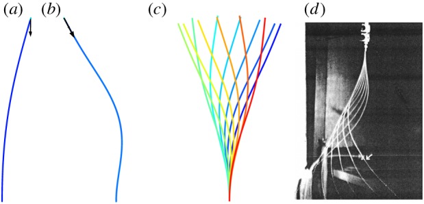
Well-known cases in which steady axial loading or flow leads to instability. (a) A compressive tip load with a fixed direction causes buckling (a static pitchfork bifurcation) when the force exceeds the critical value 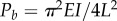 . (b,c) A compressive tip load that remains tangent to the beam (a non-conservative follower load) leads to oscillatory motion known as flutter, via a dynamic Hopf bifurcation, when the force exceeds a critical value
  (animation in electronic supplementary material, movie M1). (d) Flutter in a flexible tube conveying water. Instability occurs above a critical flow rate. Panel (d) is from Greenwald & Dugundji [30] reproduced with permission from Paidoussis [31]. (Online version in colour.)
The idea that steady dynein activity is sufficient to cause flagellar beating is supported by results from three different, but complementary, mathematical methods: (i) stability analysis of the linearized partial differential equations (PDEs) of doublet motion, using representative, realistic values for biophysical parameters including doublet tension, (ii) simulation of nonlinear equations of doublet motion, generalized from prior work [13,33], and (iii) simulation of three-dimensional (3D) finite-element (FE) models of flagella subjected to steady, distributed, axial inter-doublet forces. Each model and analysis, described in the sections below, predicts oscillatory, propulsive waves propagating from the base to tip of the flagellum.
2. Modelling and analysis of flagella
2.1. Axoneme structure and loading
Flagellar bending is caused by the activity of dynein arms between the outer microtubule doublets (figure 3; electronic supplementary material, figures S1 and S2). Dynein arms are permanently attached to the A-microtubule of doublet N; these arms transiently attach and ‘walk’ towards the base of the B-microtubule of doublet N + 1, exerting a tipward force on the higher numbered doublet. In combination with passive components, such as radial spokes, and nexin links, dynein forces also produce bending moments. If dynein activity occurs only between doublets on one side the entire flagellum will bend in response (figure 3a). The side that produces the ‘principal’, or P bend, is denoted the P side; dynein activity on the other (R) side produces the reverse (R) bend. If equal dynein activity occurs between doublet pairs on opposite sides of the flagellum (figure 3b), the net bending moment will be zero, and the equilibrium configuration of the flagellum will be straight (and slightly twisted). However, the equilibrium may not be stable.
Figure 3.
Simplified mechanical models of the axoneme. Selected longitudinal members (outer doublets) experience distributed axial loads and bending moments due to dynein activity. Colour indicates axial stress. (a,b) 3D model with six outer doublets. (a) Steady, uniform dynein force applied between doublets on one side (e.g. P) of the axoneme produces bending in one direction and a small amount of twist. (b) Steady dynein loading applied between doublet pairs equally on both P and R sides of the axoneme leads to a straight, slightly twisted configuration, with axial stress in doublets. (c) A 2D model showing steady, distributed axial loads and axial stress, in response to steady dynein activity on a single (P or R) side. (d) Axial stress in a 2D model assuming equal activity on both P and R sides. (Online version in colour.)
When dynein activity is not uniform around the circumference (as in figure 3a,b) some doublets may be under significant tensile or compressive loads, with respect to critical values for beam instability (buckling or flutter). In flagella of Chlamydomonas reinhardtii, there are 19 dynein heavy chains per 96 nm repeat between each doublet pair, or over 195 arms µm−1. Each arm may exert at least 2–4 pN [34,35] average force, so that coordinated dynein activity could lead to axial forces well over 1000 pN at the base of a flagellum. For comparison, the critical buckling load for a 12 µm long microtubule doublet with (order of magnitude) flexural rigidity EI = 100 pN µm2 is 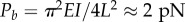 . Why do not axonemal doublets fail by buckling? One reason is that most doublets experience dynein forces in both directions (though the net dynein force will likely be non-zero). In addition, doublets under compression are connected by other axoneme components to doublets that are under tension. Nonetheless, axial loads are clearly significant, though they have not been considered in most models, the notable exception being the GC hypothesis [17–19].
To gain insight into the mechanism of instability, we first represent the 3D mechanics of the axoneme by a two-dimensional (2D) model (figure 3c,d) and a corresponding set of one-dimensional (1D) PDEs. Although 3D structural models are straightforward to simulate using FE methods, analysis of 1D PDEs is much more efficient and can provide greater insight into mechanisms. Figure 3c illustrates the accumulation of axial stress due to distributed dynein forces in a 2D, two-doublet model. Figure 3d shows the scenario in which the net bending moments are zero (counteracted by the opposing doublet pair), but the net axial forces are significant. The equations of motion for this situation were derived (electronic supplementary material) and analysed to determine the existence and nature of structural instability. To confirm and supplement the analysis of these 1D PDEs, the axoneme was also modelled as a 3D structure, using commercial FE software (COMSOL v. 5.1, COMSOL, Inc., Burlington, MA, USA), and stability and oscillations were investigated in this full 3D structural FE model.
2.2. Equations of motion: one-dimensional PDE model
2.2.1. Nonlinear equations of motion for two coupled doublets
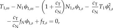
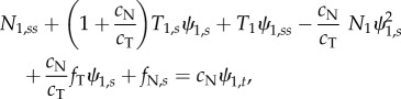
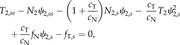
In the axoneme, doublets under compression are coupled to doublets in tension by the other components of the axoneme (dynein, radial spokes and nexin–dynein regulatory complexes). Equations governing the entire flagellum have been derived and analysed previously [5,13,15,16,33,36]. Using a similar approach to model individual doublet behaviour in a two-doublet model (electronic supplementary material, section A and figure S2), we obtain three equations for each doublet, describing the motion of a slender elastic beam moving in viscous fluid, subject to active and passive inter-doublet forces [13,15]:
 |
2.1a |
 |
2.1b |
| 2.1c |
 |
2.1d |
 |
2.1e |
| 2.1f |
In these equations  . Key variables of the model are summarized in table 1. Parameters for Chlamydomonas flagella [37,38] (table 2) are used, unless otherwise noted. Most parameters have been measured experimentally (see references in table 2), but several are simply plausible estimates (denoted by superscript ‘a’ in table 2). In addition, boundary conditions (electronic supplementary material, section A and equations A.9(i–viii)) are needed to specify that each doublet is fixed at the base and free at its tip: zero angle, displacement and velocity at the base, and zero external moments and forces at the tip.
Table 1.
Key variables of the 1D PDE model of flagella mechanics.
| variable | definition (unit) |
|---|---|
 |
tangent angle of doublet n at location s and time t (rad) |
 |
tangential component of internal force in doublet n (pN) |
 |
normal component of internal force in doublet n (pN) |
 |
bending moment in doublet n (pN μm) |
 |
inter-doublet tangential (shear) force per unit length (pN µm−1) |
 |
inter-doublet normal force per unit length (pN µm−1) |
 |
net inter-doublet moment per unit length (pN) |
Table 2.
Baseline parameter values of the 1D PDE model of flagella mechanics.
| parameter | value | units | description |
|---|---|---|---|
| cN | 0.003 | pN s µm−2 | normal viscous resistive force coefficient [37] |
| cT | cN/2 | pN s µm−2 | tangential viscous resistive force coefficient [37] |
| a | 0.200 | µm | diameter of flagellum [39] |
| L | 12 | µm | length of flagellum [40] |
| EIf | 800 | pN µm2 | flexural rigidity of flagellum [38] |
| EI | EIf/2 = 400 | pN µm2 | flexural rigidity of ‘doublet’ [38] |
| kN | 10 000 | pN µm−2 | inter-doublet normal stiffness (10 pN nm−1 µm−1)a |
| kT | 1000 | pN µm−2 | inter-doublet shear stiffness (1 pN nm−1 µm−1) [38] |
| bN |  |
pN s µm−2 | inter-doublet normal viscous resistancea |
| bT |  |
pN s µm−2 | inter-doublet shear viscous resistancea |
 |
100 000 | pN µm−4 | nonlinear normal stiffness (1 × 10⁻⁴ pN nm−3 µm−1)a |
 |
2500 | pN µm−4 | nonlinear shear stiffness (2.5 × 10⁻⁶ pN nm−3 µm−1)a |
| p | 200–800 | pN µm−1 | steady dynein force per unit length per doublet [41] |
| D(s) | 1 or 
|
Nondim. | distribution of dynein forcea |
| τ | 0.155 | s | flagellum viscoelastic time const.  (calculated) (calculated) |
| τC | τ/200 | s | inter-doublet viscoelastic time constanta |
aEstimated, not based on experimental measurement.
2.2.2. Inter-doublet forces and moments
Passive components of the axoneme resist doublet separation (electronic supplementary material, figure S2), coupling the motion of the two doublets. These components are modelled as distributed elements with linear elastic and viscous coefficients, kN and bN, respectively, and a nonlinear elastic coefficient  .
.
| 2.2 |
In the tangential direction we include a steady, distributed dynein force per unit length,  , as well as passive resistance to inter-doublet sliding. The dynein distribution function, D(s), allows the steady dynein activity to vary along the length. For longitudinally uniform dynein activity, D(s) = 1; to represent dynein activity that increases distally,
  . The moments due to equal, opposing dynein forces on the P and R sides cancel (electronic supplementary material, figure S1; figure 3b), but the moments due to passive shear resistance sum. The net inter-doublet moment per unit length is thus
| 2.3 |
where the mean shear angle is  . The coefficients kT and bT represent linear elastic and viscous resistance to sliding [5,33,40], and
  a nonlinear stiffness. The nonlinear terms in equations (2.2) and (2.3) represent assumed nonlinear, stiffening behaviour of elastic elements between doublets [8].
2.3. Stability analysis of the linearized one-dimensional PDE model
To describe small-amplitude motion about a straight, equilibrium configuration, equations (2.1a–f) may be linearized to obtain much simpler equations [5,15,42]. For a uniform, steady dynein force distribution  , dropping terms that are nonlinear in the dependent variables, the baseline tension (or compression) in the two doublets is (electronic supplementary material, figure S3):
Doublet 1:  (tension)
Doublet 2:  (compression)
Equations (2.1a–f) become
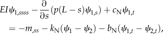 |
2.4a |
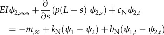 |
2.4b |
| 2.4c |
with corresponding fixed-free boundary conditions. Analogous linearized equations can be derived for distally increasing dynein activity (electronic supplementary material, figure S3).
Following [5,15,16] and [33,36] separable solutions of the form
| 2.5 |
are sought, with  (α and ω are real). If α > 0, the amplitude of the corresponding mode grows exponentially. These separable solutions are substituted into the linearized equations of motion (equations (2.4a–c)). After defining a characteristic time for the system,
  , and a normalized eigenvalue,
  , the resulting ordinary differential equations (ODEs) may be written in non-dimensional form:
| 2.6a |
 |
2.6b |
where the new non-dimensional parameters are  ,
,  and
and 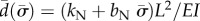 .
.
These two coupled ODEs, together with the associated fixed-free boundary conditions, form an eigenvalue problem. Approximate solutions to the eigenvalue problem can be obtained using numerical methods such as FE analysis or the method of weighted residuals [36,43] (electronic supplementary material, section B).
2.4. Simulation of the nonlinear one-dimensional PDE model
Time-domain numerical simulations of the full nonlinear PDEs [37,38] for the two-doublet model (equations (2.1a–f)), with fixed-free boundary conditions, were performed using a commercial software package (COMSOL v. 5.1; COMSOL, Inc. ). Time-domain simulation can confirm the contributions of the unstable modes predicted by stability analysis, and also allows exploration of nonlinear, transient and non-periodic behaviour. Simulations were performed with the same baseline parameters used in the stability analysis, with various values of the steady, distributed dynein load p. The 1D domain was discretized into 201 elements with quartic polynomial interpolation, and a backward differentiation algorithm with variable time step and relative tolerance of 1 × 10⁻⁸ was used to solve the system. Representative results were checked with finer mesh and smaller relative tolerance.
2.5. Simulation of three-dimensional structural finite-element models
Three-dimensional FE structural models were constructed using the same commercial FE package (COMSOL v. 5.1, COMSOL, Inc.). The basic model consisted of six slender beams (outer doublets) in a hexagonal array connected to a central beam (central pair) by radially oriented beams (spokes). Radial beam elements coupled the doublets to each other and to the central pair, providing both normal and shear stiffness. Normal and tangential viscous force components, proportional to the normal and tangential velocity components, respectively, of each doublet, represented the effect of fluid at low Reynolds number. Dynein activity was modelled by steady, uniformly distributed axial forces tangent to each doublet, and corresponding steady, distributed bending moments to satisfy equilibrium conditions (electronic supplementary material, section A and figure S2).
The 3D FE model was composed entirely of linearly elastic, beam elements. Different values of flexural rigidity (EI) and axial stiffness (EA) were used for doublets (longitudinal members) and radial spokes. In the spokes, baseline values  and
and  were multiplied by quadratic functions of curvature or strain, to model assumed nonlinear stiffening (table 3). These nonlinear terms are chosen for convenience, to represent in simple form the behaviour of elastic components with limited range. Inertial effects were included, but inertial forces are extremely small relative to elastic and viscous forces (electronic supplementary material, section C and figure S8). Mass scaling [46] was used to speed computation; the ratio of kinetic energy to potential energy was checked to confirm that inertial effects could be neglected. The system was discretized into 260 beam elements, with cubic polynomial interpolation of the displacement field. Time-marching simulations (backward differentiation, variable time step, relative tolerance 1×10⁻⁶) were performed. Representative results were checked with finer mesh and relative tolerance.
Table 3.
Parameter values used in the 3D structural FE model.
| parameter | value | units | description |
|---|---|---|---|
| E (all) | 8 × 10⁸ | Pa (pN µm−2) | Young's modulus (doublets)a [38] |
| EI (doublet) | 100 | pN µm2 | flexural rigidity (doublets)a [38] |
| EA (doublet) | 1 × 10⁶ | pN | axial stiffness × L (doublets)a |
 (spoke) (spoke) |
EI/3200 | pN µm2 | flexural rigidity (spokes) [38,44,45] |
 (spoke) (spoke) |
EA/10 | pN | axial stiffness × a/2 (spokes)b |
| EIs (spoke) |  |
pN µm2 | nonlinearity (κ = curvature)b |
| EAs (spoke) |  |
pN | nonlinearity (ɛ = axial strain)b |
| a/2 | 0.100 | µm | spoke length [39] |
| p | 50–200 | pN µm−1 | dynein force/length/doublet [41] |
| ρ | 1 × 10⁻⁶ | pN s2 µm−4 | density (all)c |
aValue of E chosen to give EI = 100 pN µm2 for each doublet. I and A estimated from doublet cross section.
bEstimated, not based on experimental measurement.
cValue of ρ is set greater than estimated physical density (approx. 1000 kg m−3 or 1 × 10⁻⁹ pN s2 µm−4) to accelerate convergence (mass scaling) [46]. The ratio of total kinetic energy to potential energy was less than 0.01 for all simulations (electronic supplementary material, figure S8), confirming that inertial effects are negligible and that the effect of mass scaling on solution accuracy is minimal.
Parameters of the 3D FE structural model (table 3) were chosen to approximate the overall parameters of Chlamydomonas reinhardtii flagella [37,38]. Each of the seven individual doublets of the 3D model is more flexible (EI = 100 pN µm2) than each of two doublets of the 1D PDE model (EI = 400 pN µm2). As a result, critical dynein force densities differed between the two models by roughly a factor of 4.
3. Results: dynamic instability and oscillations
3.1. Instability and oscillatory modes of the one-dimensional PDEs
Modes and frequencies of oscillation were obtained by analysis of the linearized PDEs of two coupled doublets (equation (2.4a,b)) subject to steady, uniformly distributed dynein loading, using the method of weighted residuals (electronic supplementary material, section B). The eigenvalues of the system depend on the amplitude, p, of the distributed dynein force (figure 4a,b). Loss of stability is indicated by a positive real part of any eigenvalue; the finite imaginary part of that eigenvalue confirms the oscillatory nature of the instability, and specifies its frequency. The eigenfunction corresponding to each unstable eigenvalue (figure 4c,d; electronic supplementary material, movie M1) describes the shape of the growing, oscillatory waveform. All eigenfunctions of this model exhibited anterograde (base-to-tip) propagation.
Figure 4.

Stability analysis of the linearized 1D PDE flagella (two-doublet) model (see figure 3d; electronic supplementary material, figure S2), with steady, uniformly distributed, axial dynein loading of amplitude p (pN µm−1). (a) Real part, α, and (b) imaginary part, ω, of eigenvalues of the linearized equations as the steady dynein load, p, is increased. A dynamic instability occurs near p = 330 pN µm−1 when the real parts of one pair of eigenvalues become positive while the imaginary parts are non-zero. (c,d) Unstable modes (eigenfunctions) of the 1D PDE model with steady, uniform, dynein loading. (c) Least stable mode for p = 350 pN µm−1 (corresponding animation is in the electronic supplementary material, movie M2). (d) Least stable mode for p = 500 pN µm−1. Each curve shows the average flagellar shape at 16 equally spaced phases in the beat, with phase depicted by colour (increasing blue to red). (e,f) Oscillatory behaviour of the 1D PDE model with steady, uniform, dynein loading, obtained by eigenanalysis of the linearized PDEs. Onset and frequency of oscillations depend on both the properties of the doublets and the inter-doublet coupling. (e) Oscillation frequency of the least stable mode versus flagellar length, L, and dynein force density, p, for conditions in which the straight equilibrium configuration is unstable. (f) Frequency of the least stable mode versus coupling stiffness, kN, and dynein force density, p.
The stability of the system can be established for multiple parameter combinations, as the stability analysis algorithm is quite efficient. As expected, increasing dynein force density and length are both associated with loss of stability (figure 4e). Increasing inter-doublet normal stiffness appears to increase the threshold for onset of oscillations (figure 4f). Neither inter-doublet viscous resistance nor shear stiffness had a significant effect on stability thresholds (electronic supplementary material, figure S4). Increasing dynein force density increases the frequency of oscillation (figure 4; electronic supplementary material, figure S4), whereas increasing the inter-doublet stiffness or viscosity tends to decrease frequency.
3.2. Propagating waves in time-domain simulations of the one-dimensional PDE model
Time-domain simulation of the system of 1D PDEs revealed oscillatory solutions (figure 5) consistent with modes predicted by stability analysis. Larger amplitude waves were obtained using the distally increasing, steady dynein force distribution. Near the stability threshold (p = 450 pN µm−1), the solution consisted of small-amplitude waves that closely resembled the single unstable mode of the linearized model. At higher values of the steady dynein load (p = 600 and 800 pN µm−1), the contributions of more than one unstable mode are apparent. All modes propagate from base to tip.
Figure 5.

Time-domain simulations of the nonlinear 1D PDE flagella (two-doublet) model under steady, distally increasing, dynein loading. (a) Angle and angular velocity at the tip of the flagellum as the amplitude of the steady dynein force density is increased from 300 to 500 pN µm−1. (b) Bifurcation diagram showing the maximum/minimum tip displacements versus distally increasing dynein force amplitude, p. (c,d) Flagellar waveforms predicted by time-domain simulation. Each panel shows the average flagella shape (mean of the two doublets) at 16 equally spaced phases of the oscillation, with phase encoded by colour (increasing blue to red). (c) p = 600 pN µm−1and (d) p = 800 pN µm−1. Corresponding animations are in the electronic supplementary material, movies M3–M5. (Online version in colour.)
Above a critical value of axial force density (figure 6), the 3D structural FE model also exhibited oscillatory, wave-like behaviour propagating from base (fixed end) to tip (free end; figure 6a,b). The qualitative behaviour of the system, including onset of oscillation, and relative deformations of doublets in compression and tension are consistent with the predictions of the 1D PDE models. The threshold for onset of oscillations is lower in the 3D FE model because the flexural modulus of each doublet (100 pN µm2) in the 3D FE model is lower than the flexural rigidity of each doublet (400 pN µm2) in the two-doublet 1D PDE system. The 3D FE model also did not include a viscous inter-doublet component, so inter-doublet time constants are lower and oscillation frequencies are higher than those of the 1D PDE model.
Figure 6.

(a,b) Snapshots from the time-domain simulation of the 3D FE (six-doublet) model of the flagellum with length L = 12 µm, total flexural rigidity EIf = 700 pN µm2, and steady, distally increasing dynein loading of amplitude p = 184 pN µm−1. Images are shown at six equally spaced phases during one period of oscillation. (a) Side-view (x–z plane). (b) End view (distal-to-proximal, x–y plane). Colour indicates axial stress along the centreline. Red (positive) = tension. Blue (negative) = compression. Corresponding animations are in the electronic supplementary material, movies M6–M7. (c) Flagella tip position versus time predicted by simulation of the 3D FE structural model of the flagellum with steady, distally increasing, distributed dynein loading, p. (i) p = 69 pN µm−1, (ii) p = 93 pN µm−1, (iii) p = 116 pN µm−1 and (iv) p = 139 pN µm−1. Above a critical value of dynein force density the straight equilibrium configuration becomes unstable, and a limit cycle emerges. (Online version in colour.)
4. Discussion and conclusion
Steady tangential dynein forces, combined with fluid–structural interactions, can initiate and maintain propulsive flagellar waveforms, without feedback to or regulation of dynein activity. Evidence for this mechanism is provided by (i) eigenanalysis of a simple linearized model, (ii) simulation of a set of nonlinear PDEs, and (iii) simulation of an FE structural model. The possibility that propulsive oscillations arise from a mechanical instability is distinct from prior models based on switching or modulation of dynein. These previous models include curvature-controlled dynein dynamics [7,13], and dynein regulation by inter-doublet forces (the GC model), which both produce propulsive, anterograde (base-to-tip) propagating waveforms [36]. Flagella models with dynein controlled by inter-doublet sliding can also produce oscillatory waveforms [5,15,16,36], though corresponding waveforms appear to be mostly retrograde. The possible role of nonlinear buckling instability in flagella was explored by Gadelha [47] in a model in which oscillations were driven by imposed, periodically varying dynein activity.
By contrast, the mechanism of fluid–structural flutter proposed here does not require dynein regulation or switching. Instead, the fluid–structural instability and resulting oscillations are driven by axial tension in individual doublets. The importance of doublet tensile and compressive loading was first raised by Lindemann [17–19] in the development of his (GC) hypothesis. However, as noted above, the GC hypothesis involves explicit mechanical feedback from transverse force to dynein activity. In the current model, dynein activity varies circumferentially (i.e. differs between doublets) and longitudinally, but does not vary with time.
Unlike classical systems that exhibit dynamic instability, inertial effects are not necessary for this instability and in fact inertia is negligible at the low Reynolds numbers involved in flagella motion. Viscosity, however, can help destabilize the flagellum by introducing phase shifts between doublet motion and force on the doublets, allowing work to be done on the flagellum during each cycle [32]. This instability occurs over a wide range of parameter values (figure 4e,f; electronic supplementary material, figure S4a,b).
The possibility of structural flutter is consistent with a number of prior experimental observations. If this model is correct, increasing steady dynein activity explains both the gradual increase in static curvature and abrupt onset of oscillations, which have been observed in reactivated axonemes as adenosine triphosphate concentration is increased [24]. The current model is also consistent with observations of intermittent buckling and re-attachment observed between doublets from which inter-doublet links are absent [48]. The effect of increased fluid viscosity on beat frequency [49–51] is captured naturally because oscillation frequency scales inversely with the major viscoelastic time constant of the system:  . The decrease in beat frequency of outer dynein arm-deficient mutants (e.g. oda2) is consistent with the general decrease in frequency with force density (figure 4e,f). The paralysis of pf13 mutants missing outer dynein arms and one species of inner dynein arm is consistent with sub-threshold dynein activity. The direction and timing of oscillations arising from fluid–structural flutter instability can be influenced by subtle cues, such as the orientation of the central pair [52], structural asymmetry of the axoneme [53] or hydrodynamic effects from neighbouring flagella [54].
The models of flagella mechanics used in this study are simplified in order to isolate and emphasize the basic mechanism of instability. These models have inevitable limitations. The effects of biased dynein activity, or inherent curvature, on flagellar stability and oscillations have not been explored. As a result, the predicted waveforms are symmetric. The interactions between doublets in the current model are not satisfactory for describing large amplitude behaviour; inter-doublet components are undoubtedly more complex than the simple spring–dashpot system used here. Neither the possible collective behaviour of dynein arms, nor their force–velocity relationships are modelled. The 3D structural FE models are composed completely of linear, elastic beam elements. While geometric nonlinearity due to large deformations is considered, possible material nonlinearities, sliding or loss of contact between components are not accounted for. A notable structural feature omitted from the current model is the twisted central pair of microtubules, which may enhance twisting or out-of-plane motion. Twisting is present, but minimal, in the current 3D FE models, but may be important in flagella beating [55].
Despite these caveats, this study shows that dynamic structural instability described here is sufficient to produce propagating, oscillatory, waveforms. In other words, dynein regulation is not necessary for flagella beating, although mechanical feedback to dynein activity may still affect waveform frequency, amplitude or symmetry. Estimates of propagating, oscillatory, dynein forces in prior studies of human sperm [23] support a role for such feedback in sperm flagella. However, this evidence remains indirect, and dependent on precise knowledge of fluid resistive force and flagellum elastic parameters.
In summary, propulsive flagellar beating can arise from steady, distributed dynein forces acting between coupled, flexible doublets in viscous fluid. This mechanism, analogous to flutter in airframes and flexible pipes, is simple, robust to parameter variations and consistent with experimental observations. The possible role of this dynamic instability in flagellar oscillations is a compelling target for future experimental and theoretical investigations.
Supplementary Material
Supplementary Material
Authors' contributions
P.V.B. and S.K.D. conceived the model combining insights from mechanics (P.V.B.) and biology (S.K.D.). P.V.B. derived equations, and performed analyses and simulations. Both authors helped draft the manuscript and gave final approval for publication.
Competing interests
We declare we have no competing interests.
Funding
Support from NSF grant no. CMMI-1265447 and CMMI-1633971 (to P.V.B.), NIH grant no. GM032842 (to S.K.D.) and the Children's Discovery Institute is gratefully acknowledged.
References
- 1.Satir P. 1968. Studies on cilia. 3. Further studies on the cilium tip and a ‘sliding filament’ model of ciliary motility. J. Cell Biol. 39, 77–94. ( 10.1083/jcb.39.1.77) [DOI] [PMC free article] [PubMed] [Google Scholar]
- 2.Satir P, Matsuoka T. 1989. Splitting the ciliary axoneme: implications for a ‘switch-point’ model of dynein arm activity in ciliary motion. Cell Motil. Cytoskeleton 14, 345–358. ( 10.1002/cm.970140305) [DOI] [PubMed] [Google Scholar]
- 3.Brokaw CJ. 2009. Thinking about flagellar oscillation. Cell Motil. Cytoskeleton 66, 425–436. ( 10.1002/cm.20313) [DOI] [PubMed] [Google Scholar]
- 4.Woolley DM. 2010. Flagellar oscillation: a commentary on proposed mechanisms. Biol. Rev. Camb. Phil. Soc. 85, 453–470. [DOI] [PubMed] [Google Scholar]
- 5.Riedel-Kruse IH, Hilfinger A, Howard J, Julicher F. 2007. How molecular motors shape the flagellar beat. HFSP J. 1, 192–208. ( 10.2976/1.2773861) [DOI] [PMC free article] [PubMed] [Google Scholar]
- 6.Lindemann CB, Lesich KA. 2010. Flagellar and ciliary beating: the proven and the possible. J. Cell Sci. 123, 519–528. ( 10.1242/jcs.051326) [DOI] [PubMed] [Google Scholar]
- 7.Brokaw CJ. 1971. Bend propagation by a sliding filament model for flagella. J. Exp. Biol. 55, 289–304. [DOI] [PubMed] [Google Scholar]
- 8.Brokaw CJ. 1972. Computer simulation of flagellar movement. I. Demonstration of stable bend propagation and bend initiation by the sliding filament model. Biophys. J. 12, 564–586. ( 10.1016/S0006-3495(72)86104-6) [DOI] [PMC free article] [PubMed] [Google Scholar]
- 9.Brokaw CJ, Rintala DR. 1975. Computer simulation of flagellar movement. III. Models incorporating cross-bridge kinetics. J. Mechanochem. Cell Motil. 3, 77–86. [PubMed] [Google Scholar]
- 10.Brokaw CJ. 1985. Computer simulation of flagellar movement. VI. Simple curvature-controlled models are incompletely specified. Biophys. J. 48, 633–642. ( 10.1016/S0006-3495(85)83819-4) [DOI] [PMC free article] [PubMed] [Google Scholar]
- 11.Brokaw CJ. 1999. Computer simulation of flagellar movement: VII. Conventional but functionally different cross-bridge models for inner and outer arm dyneins can explain the effects of outer arm dynein removal. Cell Motil. Cytoskeleton 42, 134–148. ( 10.1002/(SICI)1097-0169(1999)42:2%3C134::AID-CM5%3E3.0.CO;2-B) [DOI] [PubMed] [Google Scholar]
- 12.Brokaw CJ. 2014. Computer simulation of flagellar movement X: doublet pair splitting and bend propagation modeled using stochastic dynein kinetics. Cytoskeleton 71, 273–284. ( 10.1002/cm.21168) [DOI] [PubMed] [Google Scholar]
- 13.Hines M, Blum JJ. 1978. Bend propagation in flagella. I. Derivation of equations of motion and their simulation. Biophys. J. 23, 41–57. ( 10.1016/S0006-3495(78)85431-9) [DOI] [PMC free article] [PubMed] [Google Scholar]
- 14.Murase M, Hines M, Blum JJ. 1989. Properties of an excitable dynein model for bend propagation in cilia and flagella. J. Theor. Biol. 139, 413–430. ( 10.1016/S0022-5193(89)80219-X) [DOI] [PubMed] [Google Scholar]
- 15.Hilfinger A, Chattopadhyay AK, Julicher F. 2009. Nonlinear dynamics of cilia and flagella. Phys. Rev. E 79, 051918 ( 10.1103/PhysRevE.79.051918) [DOI] [PubMed] [Google Scholar]
- 16.Camalet S, Julicher F. 2000. Generic aspects of axonemal beating. New J. Phys. 2, 24 ( 10.1088/1367-2630/2/1/324) [DOI] [Google Scholar]
- 17.Lindemann CB. 1994. A model of flagellar and ciliary functioning which uses the forces transverse to the axoneme as the regulator of dynein activation. Cell Motil. Cytoskeleton 29, 141–154. ( 10.1002/cm.970290206) [DOI] [PubMed] [Google Scholar]
- 18.Lindemann CB. 1994. A geometric clutch hypothesis to explain oscillations of the axoneme of cilia and flagella. J. Theor. Biol. 168, 175–189. ( 10.1006/jtbi.1994.1097) [DOI] [Google Scholar]
- 19.Lindemann CB. 2002. Geometric clutch model version 3: the role of the inner and outer arm dyneins in the ciliary beat. Cell Motil. Cytoskeleton 52, 242–254. ( 10.1002/cm.10049) [DOI] [PubMed] [Google Scholar]
- 20.Lin J, Okada K, Raytchev M, Smith MC, Nicastro D. 2014. Structural mechanism of the dynein power stroke. Nat. Cell Biol. 16, 479–485. ( 10.1038/ncb2939) [DOI] [PMC free article] [PubMed] [Google Scholar]
- 21.Movassagh T, Bui KH, Sakakibara H, Oiwa K, Ishikawa T. 2010. Nucleotide-induced global conformational changes of flagellar dynein arms revealed by in situ analysis. Nat. Struct. Mol. Biol. 17, 761–767. ( 10.1038/nsmb.1832) [DOI] [PubMed] [Google Scholar]
- 22.Gaffney EA, Gadelha H, Smith DJ, Blake JR, Kirkman-Brown JC. 2011. Mammalian sperm motility: observation and theory. Annu. Rev. Fluid Mech. 43, 501–528. ( 10.1146/annurev-fluid-121108-145442) [DOI] [Google Scholar]
- 23.Smith DJ, Gaffney EA, Gadelha H, Kapur N, Kirkman-Brown JC. 2009. Bend propagation in the flagella of migrating human sperm, and its modulation by viscosity. Cell Motil. Cytoskeleton 66, 220–236. ( 10.1002/cm.20345) [DOI] [PubMed] [Google Scholar]
- 24.Geyer VF, Sartori P, Friedrich BM, Julicher F, Howard J. 2016. Independent control of the static and dynamic components of the Chlamydomonas flagellar beat. Curr. Biol. 26, 1098–1103. ( 10.1016/j.cub.2016.02.053) [DOI] [PubMed] [Google Scholar]
- 25.Dowell EH. 1982. Flutter of a buckled plate as an example of chaotic motion of a deterministic autonomous system. J. Sound Vib. 85, 333–344. ( 10.1016/0022-460X(82)90259-0) [DOI] [Google Scholar]
- 26.Dowell EH. 1995. A modern course in aeroelasticity, 3rd edn Dordrecht, The Netherlands: Kluwer Academic. [Google Scholar]
- 27.Leipholz HHE. 1983. Stability of dynamic-systems. J. Appl. Mech. 50, 1086–1096. ( 10.1115/1.3167191) [DOI] [Google Scholar]
- 28.Virgin LN. 2007. Vibration of axially loaded structures. New York, NY: Cambridge University Press. [Google Scholar]
- 29.Bolotin VV. 1963. Nonconservative problems of the theory of elastic stability. New York, NY: Macmillan. [Google Scholar]
- 30.Greenwald AS, Dugundji J. 1967. Static and dynamic instabilities of a propellant line. AFOSR Science Report: AFOSR 67–1395, MIT Aeroelastic and Structures Research Lab.
- 31.Paidoussis MP. 2008. The canonical problem of the fluid-conveying pipe and radiation of the knowledge gained to other dynamics problems across applied mechanics. J. Sound Vib. 310, 462–492. ( 10.1016/j.jsv.2007.03.065) [DOI] [Google Scholar]
- 32.Paidoussis MP. 2014. Fluid-structure interactions: slender structures and axial flow, 2nd edn Kidlington, UK: Academic Press. [Google Scholar]
- 33.Bayly PV, Wilson KS. 2014. Equations of inter-doublet separation during flagella motion reveal mechanisms of wave propagation and instability. Biophys. J. 107, 1756–1772. ( 10.1016/j.bpj.2014.07.064) [DOI] [PMC free article] [PubMed] [Google Scholar]
- 34.Reck-Peterson SL, Yildiz A, Carter AP, Gennerich A, Zhang N, Vale RD. 2006. Single-molecule analysis of dynein processivity and stepping behavior. Cell 126, 335–348. ( 10.1016/j.cell.2006.05.046) [DOI] [PMC free article] [PubMed] [Google Scholar]
- 35.Gennerich A, Carter AP, Reck-Peterson SL, Vale RD. 2007. Force-induced bidirectional stepping of cytoplasmic dynein. Cell 131, 952–965. ( 10.1016/j.cell.2007.10.016) [DOI] [PMC free article] [PubMed] [Google Scholar]
- 36.Bayly PV, Wilson KS. 2015. Analysis of unstable modes distinguishes mathematical models of flagellar motion. J. R. Soc. Interface 12, 20150124 ( 10.1098/rsif.2015.0124) [DOI] [PMC free article] [PubMed] [Google Scholar]
- 37.Bayly PV, Lewis BL, Ranz EC, Okamoto RJ, Pless RB, Dutcher SK. 2011. Propulsive forces on the flagellum during locomotion of Chlamydomonas reinhardtii. Biophys. J. 100, 2716–2725. ( 10.1016/j.bpj.2011.05.001) [DOI] [PMC free article] [PubMed] [Google Scholar]
- 38.Xu G, Wilson KS, Okamoto RJ, Shao J-Y, Dutcher SK, Bayly PV. 2016. Flexural rigidity and shear stiffness of flagella estimated from induced bends and counterbends. Biophys. J. 110, 2759–2768. ( 10.1016/j.bpj.2016.05.017) [DOI] [PMC free article] [PubMed] [Google Scholar]
- 39.Nicastro D, et al. 2006. The molecular architecture of axonemes revealed by cryoelectron tomography. Science 313, 944–948. ( 10.1126/science.1128618) [DOI] [PubMed] [Google Scholar]
- 40.Bayly PV, Lewis BL, Kemp PS, Pless RB, Dutcher SK. 2010. Efficient spatiotemporal analysis of the flagellar waveform of Chlamydomonas reinhardtii. Cytoskeleton 67, 56–69. ( 10.1002/cm.20424) [DOI] [PMC free article] [PubMed] [Google Scholar]
- 41.Shingyoji C, Higuchi H, Yoshimura M, Katayama E, Yanagida T. 1998. Dynein arms are oscillating force generators. Nature 393, 711–714. ( 10.1038/31520) [DOI] [PubMed] [Google Scholar]
- 42.Fu HC, Wolgemuth CW, Powers TR. 2008. Beating patterns of filaments in viscoelastic fluids. Phys. Rev. E 78, 041913. ( 10.1103/PhysRevE.78.041913) [DOI] [PubMed] [Google Scholar]
- 43.Meirovitch L. 1997. Principles and techniques of vibrations. Upper Saddle River, NJ: Prentice Hall. [Google Scholar]
- 44.Minoura I, Yagi T, Kamiya R. 1999. Direct measurement of inter-doublet elasticity in flagellar axonemes. Cell Struct. Funct. 24, 27–33. ( 10.1247/csf.24.27) [DOI] [PubMed] [Google Scholar]
- 45.Yagi T, Kamiya R. 1995. Novel mode of hyper-oscillation in the paralyzed axoneme of a Chlamydomonas mutant lacking the central-pair microtubules. Cell Motil. Cytoskeleton 31, 207–214. ( 10.1002/cm.970310304) [DOI] [PubMed] [Google Scholar]
- 46.Belytschko T, Liu WK, Moran B, Elkhodary KI. 2014. Nonlinear finite elements for continua and structures, 2nd edn Chichester, UK: Wiley. [Google Scholar]
- 47.Gadelha H, Gaffney EA, Smith DJ, Kirkman-Brown JC. 2010. Nonlinear instability in flagellar dynamics: a novel modulation mechanism in sperm migration? J. R. Soc. Interface 7, 1689–1697. ( 10.1098/rsif.2010.0136) [DOI] [PMC free article] [PubMed] [Google Scholar]
- 48.Aoyama S, Kamiya R. 2005. Cyclical interactions between two outer doublet microtubules in split flagellar axonemes. Biophys. J. 89, 3261–3268. ( 10.1529/biophysj.105.067876) [DOI] [PMC free article] [PubMed] [Google Scholar]
- 49.Yagi T, Minoura I, Fujiwara A, Saito R, Yasunaga T, Hirono M, Kamiya R. 2005. An axonemal dynein particularly important for flagellar movement at high viscosity. Implications from a new Chlamydomonas mutant deficient in the dynein heavy chain gene DHC9. J. Biol. Chem. 280, 41 412–41 420. ( 10.1074/jbc.M509072200) [DOI] [PubMed] [Google Scholar]
- 50.Wilson KS, Gonzalez O, Dutcher SK, Bayly PV. 2015. Dynein-deficient flagella respond to increased viscosity with contrasting changes in power and recovery strokes. Cytoskeleton 72, 477–490. ( 10.1002/cm.21252) [DOI] [PMC free article] [PubMed] [Google Scholar]
- 51.Brokaw CJ. 1996. Microtubule sliding, bend initiation, and bend propagation parameters of Ciona sperm flagella altered by viscous load. Cell Motil. Cytoskeleton 33, 6–21. ( 10.1002/(SICI)1097-0169(1996)33:1%3C6::AID-CM2%3E3.0.CO;2-C) [DOI] [PubMed] [Google Scholar]
- 52.Smith EF. 2002. Regulation of flagellar dynein by the axonemal central apparatus. Cell Motil. Cytoskeleton 52, 33–42. ( 10.1002/cm.10031) [DOI] [PubMed] [Google Scholar]
- 53.Bui KH, Sakakibara H, Movassagh T, Oiwa K, Ishikawa T. 2009. Asymmetry of inner dynein arms and inter-doublet links in Chlamydomonas flagella. J. Cell Biol. 186, 437–446. ( 10.1083/jcb.200903082) [DOI] [PMC free article] [PubMed] [Google Scholar]
- 54.Brumley DR, Wan KY, Polin M, Goldstein RE. 2014. Flagellar synchronization through direct hydrodynamic interactions. eLife 3, e02750 ( 10.7554/eLife.02750) [DOI] [PMC free article] [PubMed] [Google Scholar]
- 55.Mitchell DR, Nakatsugawa M. 2004. Bend propagation drives central pair rotation in Chlamydomonas reinhardtii flagella. J. Cell Biol. 166, 709–715. ( 10.1083/jcb.200406148) [DOI] [PMC free article] [PubMed] [Google Scholar]
Associated Data
This section collects any data citations, data availability statements, or supplementary materials included in this article.