Abstract
Precursor solution of CH3NH3PbI3-xClx for perovskite solar cells was conventionally prepared by mixing PbCl2 and CH3NH3I with a mole ratio of 1:3 (PbCl2:CH3NH3I). While in the present study, CH3NH3PbI3-xClx-based solar cells were fabricated using the precursor solutions containing PbCl2 and CH3NH3I with the mole ratios of 1:3, 1.05:3, 1.1:3, and 1.15:3, respectively. The results display that the solar cells with the mole ratio of 1.1:3 present higher power conversion efficiency and less I-V hysteresis than those with the mole ratio of 1:3. Based on some investigations, it is concluded that the higher efficiency could be due to the smooth and pinhole free film formation, high optical absorption, suitable energy band gap, and the large electron transfer efficiency, and the less I-V hysteresis may be attributed to the small low frequency capacitance of the device.
Keywords: I-V hysteresis, Precursor solution composition, CH3NH3PbI3-xClx
Background
Organometal halide perovskite solar cells (PSCs) have attracted much attention over the last several years due to their outstanding properties, such as large absorption coefficient, high electron-hole diffusion length, and high charge carrier mobility [1–6]. The power conversion efficiency (PCE) has increased from 3.8 to 22% [7]. The typical architectures of PSCs mainly contain electron transporting layer (ETL)/perovskite/hole transporting layer (HTL) (n-i-p) and HTL/perovskite/ETL (p-i-n) structures [8]. In the CH3NH3PbX3 (X = I, Br, Cl) family, a mixed halide perovskite CH3NH3PbI3-xClx (MAPbI3-xClx) has been proved a large diffusion length (~1 μm), which could be applied for planar heterojunction solar cells with improved device performance [9, 10]. Some groups have reported the results of the MAPbI3-xClx-based solar cells [11–13], in which the highest PCE is 19.3% [14].
The precursor solution of MAPbI3-xClx is conventionally prepared by mixing PbCl2 and CH3NH3I with a mole ratio of 1:3 (PbCl2:CH3NH3I). While there was no or only trace amount of Cl to be detected [15, 16]. Some studies have been performed to investigate the role of Cl in the MAPbI3-xClx film formation [17, 18]. A widely accepted opinion is that Cl ion in organometal halide perovskite can boost the mobility of excitons and the charge carrier transport [19–21]. A few groups have fabricated MAPbI3-xClx solar cells using the precursor solutions containing excess PbCl2 to investigate its effect on the performance of solar cells based on the I-V measurement with single scan direction [18, 21–23]. It has been reported that hysteretic effects were observed during the I-V measurement of the perovskite solar cells [24]. I-V hysteresis could lead to an over- or underestimation of the PCE if it is not considered. Up to now, there are few reports to investigate the effects of excess PbCl2 on the PCE and I-V hysteresis of MAPbI3-xClx solar cells by considering the hysteretic effect.
Therefore in the present study, MAPbI3-xClx-based solar cells were fabricated using the precursor solutions containing different mole ratios of PbCl2, and CH3NH3I. I-V measurements were carried out with reverse scan (RS) and forward scan (FS). The photovoltaic parameters were obtained from the I-V curves averaged with RS and FS. Based on the measurements, the effects of excess PbCl2 on the PCE and the I-V hysteresis of the solar cells were investigated. One of the novelties of this work is that the photovoltaic parameters were obtained by an average of RS and FS to improve the accuracy of data. The other is the observation and investigation of the effect of excess PbCl2 on I-V hysteresis.
Methods
Materials preparation
Methylammonium iodide (CH3NH3I) was synthesized with a method reported in the literature [25]. The perovskite precursor solutions (40 wt%) were obtained by mixing PbCl2 and CH3NH3I (MAI) in anhydrous N,N-Dimethylformamide (DMF) at 60 °C with the mole ratios of 1:3, 1.05:3, 1.1:3, and 1.15:3 (PbCl2 to MAI), respectively.
Solar cell fabrication
Perovskite solar cells with a structure of n-i-p were fabricated. FTO-coated glass substrate (~15 ohm/sq, NPG, Japan) was patterned and cleaned with detergent, acetone, 2-propanol, and ethanol for 15 min by sonication. Then the substrate was treated by oxygen plasma for 20 min. A hole-blocking layer of compact TiO2 was deposited by spin-coating, a mildly acidic solution of titanium isopropoxide (Aladdin reagent) in ethanol (350 μl in 5 ml ethanol with 0.013 M HCl) at 2000 rpm for 30 s and annealed at 500 °C for 30 min. A mesoporous TiO2 layer composed of commercial TiO2 paste (Dyesol 18NRT, Dyesol) diluted in ethanol (1:3.5, weight ratio) was then deposited on the top of compact layer by spin-coating at 5000 rpm for 30 s. After drying at 125 °C, the TiO2 films were annealed at 500 °C for 30 min. The perovskite precursor solution was spin-coated on the mesoporous TiO2 film at 2000 rpm for 45 s in an argon-filled glove box. The sample was dried on a hotplate for 60 min at 110 °C. The hole-transporter layer was formed by spincoating a spiro-OMeTAD solution at 2000 rpm for 45 s. Finally, a gold layer with the thickness of 80 nm was deposited on top of the device by thermal evaporation in air.
Characterization
X-ray diffraction (XRD) patterns were carried out on a DX-2700 diffractometer. UV-vis absorption spectra were performed on a UV–vis spectrophotometer (Varian Cary 5000). Morphologies and microstructures were obtained by a scanning electron microscope (SEM, JEM-7001 F, JEOL). Photocurrent-voltage (I-V) curves were carried out with a Keithley 2440 Sourcemeter under AM 1.5 G illumination with 100-mW/cm2 intensity from a Newport Oriel Solar Simulator. The active area of the device was 0.1 cm2 determined with a mask. Steady-state photoluminescence (PL) and time-resolved photoluminescence (TRPL) spectra were collected using a fluorometer (FLS 980E, Edinburgh Photonics). Capacitance-frequency measurements were performed under a forward bias of 0.6 V under 1 sun illumination conditions using an electrochemical workstation (RST5200, Zhengzhou Shiruisi Instrument Co., Ltd.) with the frequency range from 0.1 to 1000 Hz. The electrochemical impedance (IS) measurements were carried out with an electrochemical workstation (CHI660e, Shanghai CHI Co., Ltd.) in the frequency range from 0.1 to 100 kHz, in which an alternative signal with 5 mV magnitude was applied.
Results and discussion
Figure 1 shows the XRD patterns of MAPbI3-xClx films with different mole ratios. Three main diffraction peaks at about 14.2°, 28.6°, and 43.1° are ascribed to (110), (220), and (330) lattice planes of halide perovskite with a tetragonal structure [26]. This indicates that the perovskite films with tetragonal structure are formed. A weak peak located at 12.7° for the sample with the ratio of 1.1:3 (Fig. 1b) can be assigned to the (001) diffraction peak of PbI2 [10]. The peak at about 15.6° for the samples with the mole ratios of 1.1:3 and 1.15:3 (Fig. 1c) can be assigned to the (110) diffraction peak of CH3NH3PbCl3 [18]. This agrees with the previous reports that Cl incorporation in an iodide-based structure was only at low concentration, and phase separation readily occurred with increased concentration [22, 27]. The PbI2 phase appeared for the sample with the mole ratio of 1.1:3 and then disappeared for that with the mole ratio of 1.15:3 (Fig. 1b). While the CH3NH3PbCl3 phase appeared in both the samples with the mole ratios of 1.1:3 and 1.15:3 (Fig. 1c). This is in accord with the reported MAPbI3-xClx film growth process [23]. As a nucleation center, PbCl2 induces the nucleation of PbI2. PbI2 acts with MAI to form the perovskite film and exhausts the available Pb ions to form CH3NH3PbCl3.
Fig. 1.
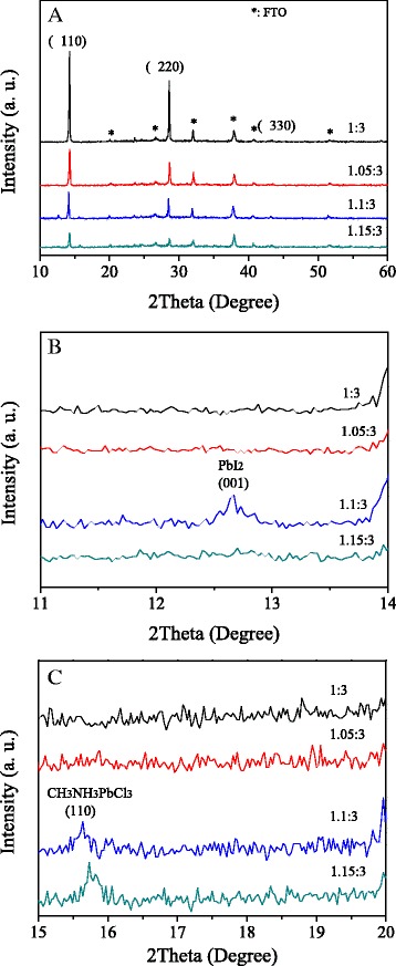
XRD patterns of MAPbI3-xClx films with different mole ratios at the range of (a) 10-60 degree, (b) 11-14 degree, and (c) 15-20 degree
Figure 2a shows the UV-vis absorption spectra of MAPbI3-xClx films with different mole ratios. The absorption intensity increases firstly, and then decreases with the increase of mole ratio, which is the strongest at the mole ratio of 1.1:3. Figure 2b shows the absorption spectra of MAPbI3-xClx films at the range from 730 to 800 nm. The absorption edge is obtained by extrapolating from the absorption of direct transition [28]. The band gap of MAPbI3-xClx can be estimated from the absorption edge to be 1.573, 1.580, 1.598, and 1.596 eV for MAPbI3-xClx with the mole ratio of 1:3, 1.05:3, 1.1:3, and 1.15:3, respectively.
Fig. 2.
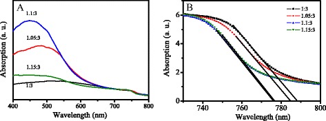
UV-vis absorption spectra of MAPbI3-xClx films with different mole ratios at the range of (a) 400-800 nm, and (b) 730-800 nm
Figure 3 shows the SEM images of the MAPbI3-xClx films with different mole ratios. It is observed that some needle-like crystals for the film with the mole ratio of 1:3 (Fig. 3a). The films with the mole ratios of 1.05:3 and 1.15:3 become smooth and cover all the substrate with some small pinholes (Fig. 3b, d). At the mole ratio of 1.1:3, the pinholes disappeared and the substrate was fully covered by the MAPbI3-xClx film (Fig. 3c). According to the previous reports [23, 29], PbCl2 colloids in the precursor solution act as heterogeneous nucleation sites for the perovskite film formation. When excess PbCl2 was introduced, the heterogeneous nucleation sites increased rationally, which possibly enhanced the morphology eventually. As the amount of PbCl2 further increased, the grain size of the perovskite film slightly increased, and the surface becomes mother.
Fig. 3.
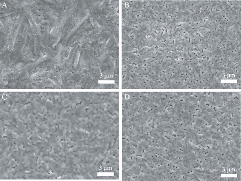
SEM images of the MAPbI3-xClx films with the mole ratio of (a) 1:3, (b) 1.05:3, (c) 1.1:3, and (d) 1.15:3
Figure 4a shows the PL spectra of MAPbI3-xClx films with different mole ratios on FTO substrate. The peak at ~780 nm could be from the emission of MAPbI3-xClx [9]. The PL intensities of the films with the mole ratios of 1.05:3, 1.1:3, and 1.15:3 are higher than that of 1:3. The TRPL spectra of MAPbI3-xClx films with different mole ratios on FTO substrate are shown in Fig. 4b. The TRPL curve was fitted with an exponential diffusion model, and the exciton lifetime is 58, 79, 67, and 177 ns for the perovskite film with the mole ratio of 1:3, 1.05:3, 1.1:3, and 1.15:3, respectively. The exciton lifetimes of the films with the mole ratio of 1.05:3, 1.1:3, and 1.15:3 are longer than that of that of 1:3. The higher PL intensities could be due to their longer exciton lifetimes [30, 31]. The enhanced exciton lifetime indicates the reduced recombination in the MAPbI3-xClx films. To investigate the charge transfer between MAPbI3-xClx film and TiO2, the PL spectra of FTO/TiO2/MAPbI3-xClx samples were performed and shown in Fig. 4c. Compared with the PL spectra of FTO/MAPbI3-xClx (Fig. 4a), there is a quenching effect when the MAPbI3-xClx layer contacts with TiO2 film, which is due to the electron injection from MAPbI3-xClx to TiO2. The charge transfer efficiency can be estimated by the PL intensity ratio of FTO/TiO2/MAPbI3-xClx to FTO/MAPbI3-xClx, which is 0.25, 0.21, 0.19, and 0.24 for the perovskite films with the mole ratio of 1:3, 1.05:3, 1.1:3, and 1.15:3, respectively. The PL intensity ratio of the sample with the mole ratio of 1.1:3 is smaller than the others, which indicates a more efficient electron transfer to TiO2. This could be due to a stronger interfacial coupling at the interface [32].
Fig. 4.
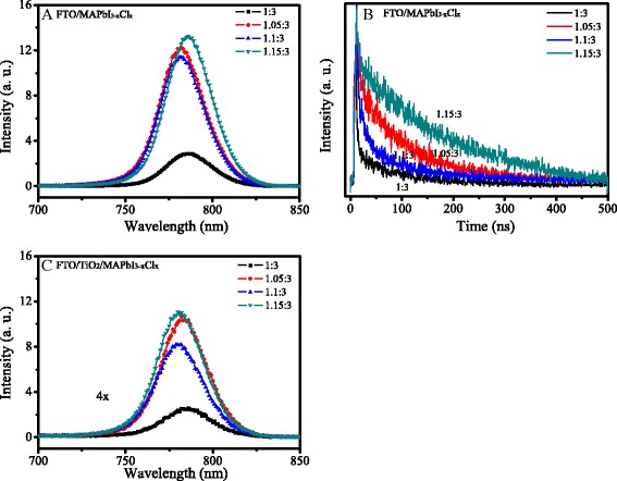
a PL and b TRPL spectra of FTO/MAPbI3-xClx samples. c PL spectra of FTO/TiO2/MAPbI3-xClx samples
Perovskite solar cells were fabricated using the precursor solutions with different mole ratios with a structure of FTO/c-TiO2/mp-TiO2/MAPbI3-xClx/spiro-oMeTAD/Au. Figure 5 shows the photovoltaic parameters of the solar cells, which were obtained from 20 pieces of devices for each of precursor solutions. The short current (J sc), open voltage (V oc), fill factor (FF) and power conversion efficiency (PCE) were obtained from I-V curves averaged with reverse scan (RS) and forward scan (FS). These parameters are listed in Table 1. With the increase of mole ratio, the parameters of the solar cells were firstly increased, and then decreased. The solar cells with the mole ratio of 1.1:3 present an enhanced performance. Compared with those of solar cells with the mole ratio of 1:3, the V oc, J sc, FF, and PCE of the solar cells with the mole ratio of 1.1:3 were increased to 0.88 V, 19.7 mA/cm2, 65%, and 11.3% from 0.76 V, 18.1 mA/cm2, 61.9%, and 8.8%, respectively.
Fig. 5.
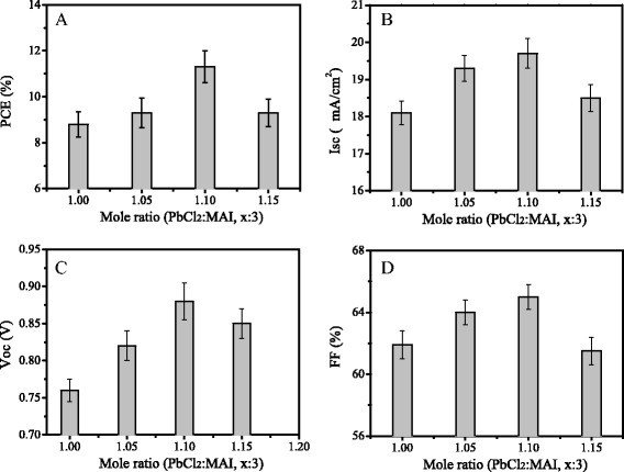
Photovoltaic parameters of the solar cells using the precursor solutions with different mole ratios. a Isc, b Voc, c FF, and d PCE. The data were obtained from 20 pieces of devices for each of precursor solutions
Table 1.
Photovoltaic parameters of perovskite solar cells as a function of different mole ratios of PbCl2 and MAI
| PbCl2:MAI | V oc (V) | J sc (mA/cm2) | FF (%) | η (%) |
|---|---|---|---|---|
| 1:3 | 0.76 ± 0.01 | 18.1 ± 0.2 | 61.9 ± 1.6 | 8.8 ± 0.1 |
| 1.05:3 | 0.82 ± 0.02 | 19.3 ± 0.3 | 64.0 ± 1.5 | 9.3 ± 0.2 |
| 1.1:3 | 0.88 ± 0.01 | 19.7 ± 0.1 | 65.0 ± 0.5 | 11.3 ± 0.2 |
| 1.15:3 | 0.85 ± 0.01 | 18.5 ± 0.2 | 61.5 ± 1.5 | 9.3 ± 0.3 |
Figure 6 shows the current density-voltage (I-V) curves of the best solar cells using the precursor solutions with different mole ratios. It was found that the degree of I-V hysteresis depends on the precursor composition. This phenomenon was always observed in our experiments. I-V hysteresis index (HI) is defined by the following equation [33],
where J RS(0.8V oc) and J FS(0.8V oc) stand for the photocurrent density at 80% of V oc for the RS and FS, respectively. The calculated hysteresis index values are 0.164, 0.085, 0.019, and 0.066 for the I-V curves with the mole ratio of 1:3, 1.05:3, 1.1:3, and 1.15:3, respectively. With the increase of mole ratio, the hysteresis degree first decreases, and then increases. At the mole ratio of 1.1:3, the hysteresis index value is the smallest. The high PCE of 11.55% with less I-V hysteresis was obtained using the precursor solution with the mole ratio of 1.1:3.
Fig. 6.
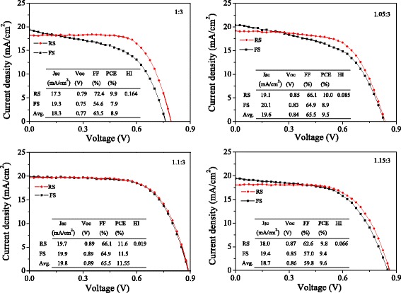
Current density-voltage (I-V) curves of the best solar cells using the precursor solutions with different mole ratios
To get an insight into the enhanced performance and less I-V hysteresis of the solar cells with the mole ratio of 1.1:3, some investigations were performed. Based on the energy band gaps calculated from the absorption spectra (Fig. 2) and the literature [33], the energy band diagrams of TiO2, MAPbI3-xClx, and Spiro-OMeTAD are shown in Fig. 7. The conduction band offset between MAPbI3-xClx and TiO2 is the largest for the mole ratio of 1.1:3 due to its wide band gap, which might be one of the reasons to present a higher voltage [28]. Moreover, the larger conduction band offset might contribute to its increased current density, because the band offset has been proved to be a driving force for charge transfer between conduction bands in the heterojunction [34, 35]. This speculation was confirmed by the photoluminescence (PL) results.
Fig. 7.
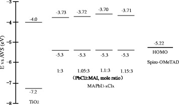
Schematic of the energy band diagrams of TiO2, MAPbI3-xClx, and Spiro-OMeTAD.
Hysteretic effects during I-V measurements have been observed in perovskite solar cells. It has been proposed that the slow decay process of the capacitive charging or discharging current during voltage sweep induces the non-steady state photocurrent and I-V hysteresis [33, 36, 37]. The non-steady state photocurrents could be due to the capacitance at low frequency (0.1 ~ 1 Hz) resulting from electrode polarization at perovskite/electrode interfaces [33]. To understand the I-V hysteresis of the solar cells with different precursor compositions, the capacitance of the devices were directly measured with an electrochemical workstation. Figure 8 shows the dependence of capacitance on frequency. The low frequency capacitance (C LF) is observed near 10−1 Hz. With the increase of the mole ratio, C LF decreases firstly, and then increases, which is the smallest at the mole ratio of 1.1:3. The smaller C LF indicates the less polarization which could be the origin of the I-V hysteresis [33]. The variation of C LF with the mole ratio agrees with the I-V hysteresis tendency shown in Fig. 4.
Fig. 8.
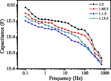
Capacitance-frequency plots of the solar cells directly measured from an electrochemical workstation
To investigate the reason of capacitance decrease, the impedance spectra of the solar cells were measured. Figure 9a shows the Nyquist plots of the cells based on the different mole ratios, in which the symbols are the experimental data and the solid lines are the fitting results. There are two RC arcs contained in the plots. Figure 9b shows the equivalent circuit used to fit the data. The high-frequency RC element could be ascribed to the contact resistance (R co) at the interfaces, while the low-frequency element may be attributed to the recombination resistance (R rec) and chemical capacitance (C μ) of the device, and the R s is a series resistance [38]. The parameters obtained by fitting are listed in Table 2. The R co (10.6 Ω) of solar cells based on precursor solution with mole ratio of 1.1:3 is smaller than that of the other precursor solution. This indicates that the perovskite film with the mole ratio of 1.1:3 provides better contact with electron transporting layer and hole transporting layer than the other perovskite film. Thus, the decreased capacitance of the solar cells with the mole ratio of 1.1:3 could be due to the better contact of perovskite film with ETL and HTL [39].
Fig. 9.
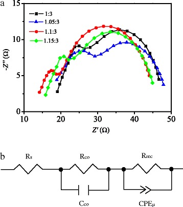
a Typical Nyquist plots for the perovskite solar cells. The simulation result (solid line) is fitted to experimental data (symbols). b Equivalent circuit applied to fit the Nyquist plots
Table 2.
Fitting parameters for EIS data
| Sample | R s/Ω | R co/Ω | R rec/Ω | C co/F | CPE-T/F |
|---|---|---|---|---|---|
| 1:3 | 17.7 | 21.0 | 23.7 | 1.5E-7 | 3.6E-6 |
| 1.05:3 | 17.1 | 17.8 | 27.5 | 1.6E-8 | 2.5E-6 |
| 1.1:3 | 13.5 | 10.6 | 28.5 | 1.2E-7 | 6.9E-7 |
| 1.15:3 | 15.2 | 16.8 | 27.6 | 1.3E-7 | 5.1E-6 |
Conclusion
The solar cells based on MAPbI3-xClx were fabricated using the precursor solutions containing the mole ratio of 1:3, 1.05:3, 1.1:3, and 1.15:3. I-V curves were obtained by both reverse scan and forward scan, from which the photovoltaic parameters were calculated by taking the average of them. The results displayed that the solar cells with the mole ratio of 1.1:3 present higher PCE and less I-V hysteresis. To get an insight into the results, some investigations were performed. The higher PCE could be due to the smooth and pinhole-free film formation, high optical absorption, suitable energy band gap, and the large electron transfer efficiency. The less I-V hysteresis may be attributed to the small low frequency capacitance of the device.
Acknowledgments
Funding
This work is supported by the NSFC-Henan Province Joint Fund (U1604144), Science Fund of Henan Province (162300410020), National Science Research Project of Education Department of Henan Province (No.17A140005), Science and Technology Development Project of Henan Province (No.142102210389), and Program for Innovative Research Team (in Science and Technology) in University of Henan Province (No. 13IRTSTHN017).
Authors’ contributions
Z-LZ, B-QM, and Y-LM carried out the main part of experiment and drafted the manuscript. Other authors provided assistance with experimental measurements, data analysis, and the manuscript writing. All authors read and approved the final manuscript.
Competing interests
The authors declare that they have no competing interests.
References
- 1.Dong Q, Fang Y, Shao Y, Mulligan P, Qiu J, Cao L, Huang J. Electron-hole diffusion lengths > 175 μm in solution-grown CH3NH3PbI3 single crystals. Science. 2015;347:967–970. doi: 10.1126/science.aaa5760. [DOI] [PubMed] [Google Scholar]
- 2.Chen LC, Chen JC, Chen CC, Wu CG. Fabrication and properties of high-efficiency perovskite/PCBM organic solar cells. Nanoscale Res Lett. 2015;10:312. doi: 10.1186/s11671-015-1020-2. [DOI] [PMC free article] [PubMed] [Google Scholar]
- 3.Zhu L, Shi J, Lv S, Yang S, Xu X, Xu Y, Xiao J, Wu H, Luo Y, Li D, Meng Q. Temperature-assisted controlling morphology and charge transport property for highly efficient perovskite solar cells. Nano Energy. 2015;15:540–548. doi: 10.1016/j.nanoen.2015.04.039. [DOI] [Google Scholar]
- 4.Jeon NJ, Noh JH, Yang WS, Kim YC, Ryu SC, Seo JW, Seok SI. Compositional engineering of perovskite materials for high-performance solar cells. Nature. 2015;517:476–480. doi: 10.1038/nature14133. [DOI] [PubMed] [Google Scholar]
- 5.Liu DT, Li SB, Zhang P, Wang YF, Zhang R, Sarvarib H, Wang F, Jiang Wu J, Wang ZM, Chen ZD. Efficient planar heterojunction perovskite solar cells with Li-doped compact TiO2 layer. Nano Energy. 2017;31:462–468. doi: 10.1016/j.nanoen.2016.11.028. [DOI] [Google Scholar]
- 6.Li SB, Zhang B, Wang YF, Sarvari H, Liu DT, Wu J, Yang YJ, Wang ZM, Zhi David Chen ZD. Interface engineering of high efficiency perovskite solar cells based on ZnO nanorods using atomic layer deposition. Nano Res. 2016 [Google Scholar]
- 7.National renewable energy laboratory best research-cell efficiencies. www.nrel.gov/ncpv/images/efficiency_chart.jpg. Accessed 17 May 2016.
- 8.Habibi M, Zabihi F, Ahmadian-Yazdi MR, Eslamian M. Progress in emerging solution-processed thin film solar cells-Part II:Perovskite solar cells. Renew Sust Energ Rev. 2016;62:1012–1031. doi: 10.1016/j.rser.2016.05.042. [DOI] [Google Scholar]
- 9.Stranks SD, Eperon GE, Grancini G, Menelaou C, Alcocer MJP, Leijtens T, Laura M, Herz M, Petrozza A, Snaith HJ. Electron-hole diffusion lengths exceeding 1 micrometer in an organometal trihalide perovskite absorber. Science. 2013;342:341–344. doi: 10.1126/science.1243982. [DOI] [PubMed] [Google Scholar]
- 10.Edri E, Kirmayer S, Henning A, Mukhopadhyay S, Gartsman K, Rosenwakes Y, Hodes G, Cahen D. Why lead methylammonium tri-iodide perovskite-based solar cells require a mesoporous electron transporting scaffold. Nano Lett. 2014;14:1000–1004. doi: 10.1021/nl404454h. [DOI] [PubMed] [Google Scholar]
- 11.Wang W, Zhang ZB, Cai YY, Chen JS, Wang JM, Huang RY, Lu XB, Gao XS, Shui LL, Wu SJ, Liu JM. Enhanced performance of CH3NH3PbI3-xClx perovskite solar cells by CH3NH3I modification of TiO2-perovskite layer interface. Nanoscale Res Lett. 2016;11:316. doi: 10.1186/s11671-016-1540-4. [DOI] [PMC free article] [PubMed] [Google Scholar]
- 12.Liang PW, Liao CY, Chueh CC, Zuo F, Williams ST, Xin XK, Lin J, Jen AK. Additive enhanced crystallization of solution processed perovskite for highly efficient planar-heterojunction solar cells. Adv Mater. 2014;26:3748–3754. doi: 10.1002/adma.201400231. [DOI] [PubMed] [Google Scholar]
- 13.Ahmadian-Yazdi MR, Zabihi F, Habibi M, Eslamian M. Effects of process parameters on the characteristics of mixed-halide perovskite solar cells fabricated by one-step and two-step sequential coating. Nanoscale Res Lett. 2016;11:408–418. doi: 10.1186/s11671-016-1601-8. [DOI] [PMC free article] [PubMed] [Google Scholar]
- 14.Zhou HP, Chen Q, Li G, Luo S, Song T, Duan H, Hong Z, You J, Liu Y, Yang Y. Interface engineering of highly efficient perovskite solar cells. Science. 2014;345:542–546. doi: 10.1126/science.1254050. [DOI] [PubMed] [Google Scholar]
- 15.Chen Q, Zhou HP, Fang YH, Stieg AZ, Song TB, Wang HH, Xu XB, Liu YS, Lu SR, You JB, Sun P, Mckay J, Goorsky MS, Yang Y. The optoelectronic role of chlorine in CH3NH3PbI3(Cl)-based perovskite solar cells. Nat Commun. 2015;6:7269–7277. doi: 10.1038/ncomms8269. [DOI] [PMC free article] [PubMed] [Google Scholar]
- 16.Colella S, Mosconi E, Pellegrino G, Alberti A, Guerra VLP, Masi SA, Listoi A, Rizzo A, Condorelli GG, Angelis FD, Gigli G. Elusive presence of chloride in mixed halide perovskite solar cells. J Phys Chem Lett. 2014;5:3532–3538. doi: 10.1021/jz501869f. [DOI] [PubMed] [Google Scholar]
- 17.Williams ST, Zuo F, Chueh CC, Liao CY, Liang PW, Jen AKY. Role of chloride in the morphological evolution of organo-lead halide perovskite thin films. ACS Nano. 2014;8:10640–10654. doi: 10.1021/nn5041922. [DOI] [PubMed] [Google Scholar]
- 18.Yu H, Wang F, Xie FY, Li WW, Chen J, Zhao N. The role of chlorine in the formation process of CH3NH3PbI3-xClx Perovskite. Adv Funct Mater. 2010;24:7102–7108. [Google Scholar]
- 19.Zabihi F, Ahmadian-Yazdi MR, Eslamian M. Fundamental study on the fabrication of inverted planar perovskite solar cells using two-step sequential substrate vibration-assisted spray coating (2S-SVASC) Nanoscale Res Lett. 2016;11:71. doi: 10.1186/s11671-016-1259-2. [DOI] [PMC free article] [PubMed] [Google Scholar]
- 20.Zhang M, Yu H, Lyu MQ, Wang Q, Yun JH, Wang LZ. Composition-dependent photoluminescence intensity and prolonged recombination lifetime of perovskite CH3NH3PbBr3-xClx films. Chem Commun. 2014;50:11727. doi: 10.1039/C4CC04973J. [DOI] [PubMed] [Google Scholar]
- 21.Colella S, Mosconi E, Fedeli P, Listorti A, Gazza F, Orlandi F, Ferro P, Besagni T, Rizzo A, Calestani G, Gigli G, Angelis DF, Mosca R. MAPbI3-xClx mixed halide perovskite for hybrid solar cells: The role of chloride as dopant on the transport and structural properties. Chem Mater. 2013;25:4613. doi: 10.1021/cm402919x. [DOI] [Google Scholar]
- 22.Mcleod JA, Wu ZW, Sun BQ, Liu LJ. The influence of the I/Cl ratio on the performance of CH3NH3PbI3-xClx-based solar cells: why is CH3NH3I:PbCl2 = 3:1 the “magic” ratio. Nanoscale. 2016;8:6361–6368. doi: 10.1039/C5NR06217A. [DOI] [PubMed] [Google Scholar]
- 23.Huang C, Fu NQ, Liu FY, Jiang LX, Hao XJ, Huang HT. Highly efficient perovskite solar cells with precursor composition-dependent morphology. Sol Energy Mater Sol Cells. 2016;145:231–237. doi: 10.1016/j.solmat.2015.10.032. [DOI] [Google Scholar]
- 24.Unger EL, Hoke ET, Bailie CD, Nguyen WH, Bowring AR, Heumuller T, Christoforod MG, McGehee MD. Hysteresis and transient behavior in current-voltage measurements of hybrid-perovskite absorber solar cells. Energy Environ Sci. 2014;7:3690–3698. doi: 10.1039/C4EE02465F. [DOI] [Google Scholar]
- 25.Lee MM, Teuscher J, Miyasaka T, Murakami TN, Snaith HJ. Efficient hybrid solar cells based on meso-superstructured organometal halide perovskites. Science. 2012;338:643–647. doi: 10.1126/science.1228604. [DOI] [PubMed] [Google Scholar]
- 26.Stoumpos CC, Malliakas CD, Kanatzidis MG. Semiconducting tin and lead iodide perovskites with organic vations: phase transitions, high mobilities, and near-infrared photoluminescent properties. Inorg Chem. 2013;52:9019–9038. doi: 10.1021/ic401215x. [DOI] [PubMed] [Google Scholar]
- 27.Yin WJ, Shi T, Yan Y. Unique properties of halide perovskites as possible origins of the superior solar cell performance. Adv Mater. 2014;26:4653–4658. doi: 10.1002/adma.201306281. [DOI] [PubMed] [Google Scholar]
- 28.Li YL, Sun WH, Yan WB, Ye SY, Peng HT, Liu ZW, Bian ZQ, Huang CH. High-performance planar solar cells based on CH3NH3PbI3-xClx perovskites with determined chlorine mole fraction. Adv Funct Mater. 2015;25:4867–4873. doi: 10.1002/adfm.201501289. [DOI] [Google Scholar]
- 29.Tidhar Y, Edri E, Weissman H, Zohar D, Hodes G, Cahen D, Rybtchinski B, Kirmayer S. Crystallization of methylammonium lead halide perovskites: implications for photovoltaic applications. J Am Chem Soc. 2014;136:13249–13256. doi: 10.1021/ja505556s. [DOI] [PubMed] [Google Scholar]
- 30.Chen LC, Chen CC, Chen JC, Wu CG. Annealing effects on high-performance CH3NH3PbI3 perovskite solar cells prepared by solution-process. Sol Energy. 2015;122:1047–1051. doi: 10.1016/j.solener.2015.10.019. [DOI] [Google Scholar]
- 31.Roldan C, Gratia P, Zimmermann I, Grancini G, Gao P, Graetzel M, Nazeeruddin MK. High efficiency methylammonium lead triiodide perovskite solar cells: the relevance of non-stoichiometric precursors. Energy Environ Sci. 2015;8:3550–3556. doi: 10.1039/C5EE02555A. [DOI] [Google Scholar]
- 32.Mosconi E, Ronca E, Angelis FD. First-principles investigation of the TiO2/organohalide perovskites interface: The role of interfacial chlorine. J Phys Chem Lett. 2014;5:2619–2625. doi: 10.1021/jz501127k. [DOI] [PubMed] [Google Scholar]
- 33.Kim HS, Park NG (2014) Parameters affecting I-V hysteresis of CH3NH3PbI3 perovskite solar cells: effects of perovskite crystal size and mesoporous TiO2 layer. J Phys Chem Lett 5:2927-2934 [DOI] [PubMed]
- 34.Robel I, Kuno M, Kamat PV. Size-dependent electron injection from excited CdSe quantum dots into TiO2 nanoparticles. J Am Chem Soc. 2007;129:4136–4137. doi: 10.1021/ja070099a. [DOI] [PubMed] [Google Scholar]
- 35.Tvrdy K, Frantszov P, Kamat PV. Photoinduced electron transfer from semiconductor quantum dots to metal oxide nanoparticles. Proc Natl Acad Sci U S A. 2011;108:29–34. doi: 10.1073/pnas.1011972107. [DOI] [PMC free article] [PubMed] [Google Scholar]
- 36.Sanchez RS, Gonzalez VP, Lee JW, Park NG, Kang YS, Mora SI, Bisquert J. Slow dynamic processes in lead halide perovskite solar cells. J Phys Chem Lett. 2014;5:2357–2363. doi: 10.1021/jz5011187. [DOI] [PubMed] [Google Scholar]
- 37.Kim HS, Mora SI, Gonzalez PV, Fabregat SF, Juarez-Perez EJ, Park NG, Bisquert J. Mechanism of carrier accumulation in perovskite thin-absorber solar cells. Nat Commun. 2013;4:2242–2248. doi: 10.1038/ncomms3242. [DOI] [PubMed] [Google Scholar]
- 38.Kim HS, Lee JW, Yantara N, Boix PP, Kulkarni SA, Mhaisalkar S, Gratzel M, Park NG. High efficiency solid-state sensitized solar cell-based on submicrometer rutile TiO2 nanorod and CH3NH3PbI3 perovskite sensitizer. Nano Lett. 2013;13:2412–2417. doi: 10.1021/nl400286w. [DOI] [PubMed] [Google Scholar]
- 39.Kim HS, Jang IH, Ahn N, Choi M, Guerrero A, Bisquert J, Park NG. Control of I-V hysteresis in CH3NH3PbI3 perovskite solar cell. J Phys Chem Lett. 2015;6:4633–4639. doi: 10.1021/acs.jpclett.5b02273. [DOI] [PubMed] [Google Scholar]


