

Abstract
In recent years, in situ data collection has been a major focus of progress in protein crystallography. Here, we introduce the Mylar in situ method using Mylar-based sandwich plates that are inexpensive, easy to make and handle, and show significantly less background scattering than other setups. A variety of cognate holders for patches of Mylar in situ sandwich films corresponding to one or more wells makes the method robust and versatile, allows for storage and shipping of entire wells, and enables automated crystal imaging, screening, and goniometer-based X-ray diffraction data-collection at room temperature and under cryogenic conditions for soluble and membrane-protein crystals grown in or transferred to these plates. We validated the Mylar in situ method using crystals of the water-soluble proteins hen egg-white lysozyme and sperm whale myoglobin as well as the 7-transmembrane protein bacteriorhodopsin from Haloquadratum walsbyi. In conjunction with current developments at synchrotrons, this approach promises high-resolution structural studies of membrane proteins to become faster and more routine.
Short abstract
We introduce the Mylar in situ method that uses Mylar-based sandwich plates, which are advantageous over established designs. Cognate holders make the method robust and versatile and allow for automated crystal imaging, screening, and goniometer-based X-ray diffraction data collection at room temperature and under cryogenic conditions for soluble and membrane-protein crystals grown in or transferred to these plates.
1. Introduction
Crystallography is a key investigative method in structural biology. It provides three-dimensional structural information on macromolecules such as proteins or nucleic acids, which is of paramount value for understanding biomolecular function on an atomic level and for applications like designing new drugs.1 The last 15 years have seen tremendous efforts in structural genomics, including the development of new methods for automation and miniaturization to achieve high-throughput crystallography,2,3 thereby significantly decreasing the time and effort with which structures of very high quality can be obtained.4 A typical workflow in protein crystallography comprises various steps, mainly recombinant protein production, protein purification, functional and biophysical characterization of the protein sample, protein crystallization, diffraction data-collection, and subsequent data analysis. In conjunction with newly developed specialized instrumentation and tools, many steps of this workflow have been improved and accelerated. However, despite the use of robotics, obtaining well-diffracting protein crystals remains a time-consuming, iterative, trial-and-error process. Thus, the two steps of crystal optimization and data collection still are major bottlenecks in protein crystallography, bearing high potential for optimization.
In situ data collection, where crystal harvesting is avoided by directly collecting diffraction images from unperturbed crystals residing in their growth environment, has been a focus of development in recent years.5 While early in situ attempts primarily served the purpose of screening crystals and validating their diffraction quality, recent approaches aim at collecting full data sets suitable for structure determination. Current in situ technologies combine crystallization and data collection in the form of X-ray compatible crystallization plates,6−10 microfluidic devices,11−16 which also comprise combinations with microcapillaries17,18 and nanodroplets,19 or fixed-target crystallography chips.20−23 While microfluidic technologies drastically reduce sample consumption, fixed-target chips are very successful for time-resolved crystallography on proteins where crystallization conditions and crystal positions are known. Both technologies, however, require specialized equipment and rather sophisticated microfabrication and are very challenging to employ for growing membrane-protein crystals in viscous lipidic mesophases. Commercial in situ crystallization plates (e.g., CrystalQuick X Plates from Greiner Bio-One; In Situ-1 Crystallization Plates from MiTeGen; SWISSCI LCP Screening Plates from Hampton Research, or CubeCrystal Plates from Cube Biotech) are compatible with crystallization and imaging robots and thus can be used with ease for automated high-throughput screening. Limitations, however, are their costs, the requirement of specific hardware such as translational stages to align the X-ray beam with crystals in the plate, and typically their incompatibility with measurements at cryogenic conditions as well as with the collection of complete high-resolution data sets.
Some of the limitations of in situ data collection have been overcome with the advent of thin sandwich plates developed for the in meso crystallization of membrane proteins in lipidic cubic phases (LCPs).9,10 LCPs are membrane-mimetic matrices that stabilize membrane proteins while at the same time allowing for crystal contacts in a lipid-bilayer environment.24,25 Traditionally, in meso crystallization trials are set up in glass sandwich plates (Figure 1) either manually or with the help of a robot.26 While glass sandwich plates bring along several advantages for crystal imaging like optical clarity and nonbirefringence, it is not possible to use them directly (i.e., in situ) for screening or diffraction data-collection. Moreover, it is notoriously difficult to harvest small and fragile membrane-protein crystals from the highly viscous LCP.27 Recently, modified sandwich plates, so-called IMISX plates (commercially available from MiTeGen),9,10 have been described, where instead of glass plates two synthetic cyclic olefin copolymer (COC) films, this is thin, X-ray-transparent plastic sheets, form the mesophase-containing sandwich. The COC film sandwich is layered in between two glass plates to form a double-sandwich for stability, watertight sealing, and imaging purposes (Figure 1). The advantages are that the inner film sandwich is thin enough to allow for data collection and patches of the sandwich plate corresponding to one or more wells with typically several dozens of crystals can be cut out and taken to an X-ray source. Similar in situ double-sandwich plates were recently described for the growth of soluble protein crystals.7
Figure 1.
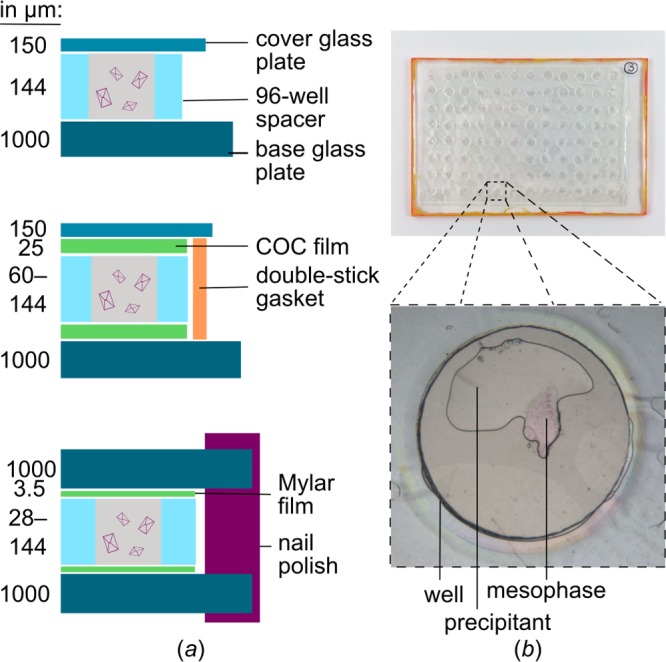
Comparison of traditional LCP glass sandwich plates and in situ double-sandwich plates. (a) Cross-sectional schematics. (Top panel) In the standard glass plate, a double-sticky 96-well spacer is sandwiched in between a base glass plate and a thinner cover glass. (Middle panel) In the IMISX method, plates consist of an inner and an outer sandwich. Two 25-μm-thick COC films and a spacer make up the inner sandwich. To keep the interior watertight, it is sandwiched in between standard glass plates, which are glued together using a double-sticky gasket. (Bottom panel) Mylar in situ plates also consist of an inner and an outer sandwich. Here, the spacer is covered on both sides by a 3.5 μm Mylar film. To prevent water loss, the inner sandwich is also sandwiched in between standard glass plates, which are sealed from the outside along the edges using nail polish. (b) Photographic image of Mylar in situ plates. An expanded view of one of the wells is shown at the bottom. The mesophase contains purple HwBR crystals, and the precipitant is colorless. Mesophase and precipitant volumes were 200 and 1000 nL, respectively. The well diameter is 5 mm.
In order to push the limits of in situ crystallography, we designed a set of tools in a parallel development, henceforth referred to as the Mylar in situ method. Our intention was to produce a low-cost, robust, easy to make and handle, and highly versatile solution of sandwich plates, called hereafter Mylar in situ plates. In addition, we designed cognate holders, which allow automated crystal imaging and screening along with goniometer-based X-ray diffraction data-collection at room temperature and under cryogenic conditions for soluble and membrane proteins grown in or transferred to these plates. We demonstrate the potential of the Mylar in situ method for obtaining high-resolution structural information by using water-soluble hen egg-white lysozyme (HEWL) and sperm whale myoglobin (SWMb) as well as the 7-transmembrane protein bacteriorhodopsin from Haloquadratum walsbyi (HwBR).28,29
2. Results and Discussion
2.1. Mylar vs COC Film
As a liquid crystal, the mesophase scatters intensely at both low and high angles. At low angles, scattering is characterized by a series of well-defined rings, while at a higher angle it is more diffuse and centered at ∼4.6 Å resolution, where it overlaps with scatter from the COC film used in the IMISX method.9,10 Both regions of scattering cause a decrease of the signal-to-noise ratio of the diffraction pattern. With very small and/or weakly scattering crystals as well as for challenging crystallographic measurements (e.g., in meso crystallography or phasing) the signal-to-noise ratio is decreased even further, necessitating the use of a different film material with lower background scattering.
The X-ray transparent film used in this study is made from Mylar instead of COC. Mylar film was chosen because it is relatively watertight, optically transparent, inexpensive, and commercially available from Premier Lab Supplies (Port St. Lucie, USA) in continuous rolls of varying thickness (e.g., 1.5 μm, 2.5 μm, 3.0 μm, or 3.5 μm). Most importantly, it is chemically inert and absorbs and scatters X-rays only weakly. Furthermore, Mylar in situ plates are of exceptionally slim design that further reduces X-ray scatter and absorption (Figure 1). At a total thickness of only 7 μm, in comparison to 50 μm in the case of COC films, the two Mylar films through which the X-rays pass in the process of in situ measurements show a lower and narrower background scatter profile, with weak, narrow maxima centered at around 4, 5, and 6 Å (Figure 2). It is conceivable that thinner COC film, which we could not source though, would be suited similarly well or even better, since it would promise a lower and more diffuse scatter profile without the biaxially oriented features seen in Mylar.
Figure 2.
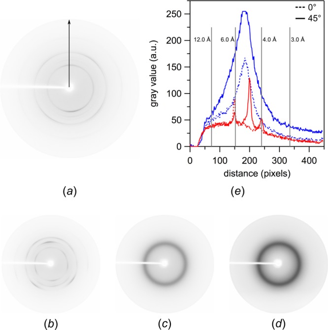
Background scattering of Mylar-based vs COC-based in situ film sandwiches (spacer thickness: 144 μm) without protein and mesophase. The background scattering of a film sandwich made from two 3.5-μm-thick layers of Mylar is shown at rotation angles of (a) 0° and (b) 45°. The corresponding background scattering of a film sandwich made from two 25-μm-thick layers of COC is shown at rotation angles of (c) 0° and (d) 45°. (e) Quantification of background scattering in terms of gray values vs the distance from the beam spot along the indicated arrow in (a). Mylar background scattering (red) is weak, with thin maxima centered at around 4, 5, and 6 Å. COC background scattering (blue) is stronger, with a broad maximum centered at ∼4.5–6 Å. In comparison, background scattering of COC is up to two times higher and five times broader than that of Mylar. Data were recorded on a rotating anode source (Supplementary Methods).
The strong background scattering from mesophase-loaded Mylar sandwiches (Figure S1c) can be reduced by working with thinner spacers, which in turn require thinner mesophase boluses (Figure S1a,b). Perforated 96-well double-sticky spacer tape of varying thickness (e.g., 28 μm, 58 μm, or 144 μm) is commercially available from Saunders (St. Paul, USA). Note that in our experience the use of thin spacers can unintentionally result in the preferential orientation of crystals along the dimension closest in size to the spacer’s thickness (Figure S2 and Note S1). Therefore, in this study, most measurements were made with spacers that were 144 μm thick.
2.2. Mylar-Based In Situ Plates
Mylar in situ double-sandwich plates are assembled essentially the same way as IMISX and standard glass plates (Figure 1 and Supplementary Methods). They can be made simply and quickly in the lab with a small amount of commercially available materials (Supplementary Methods and Note S2).
Similar to COC, the thin Mylar film is not completely watertight. Thus, the inner film sandwich is sandwiched again in between two glass plates. This double-sandwich is sealed from the outside using nail polish, a sealing method commonly used in making permanent preparations in microscopy.30 Water loss over time in Mylar in situ plates was comparable to that of the IMISX method, which uses 25-μm-thick COC films, indicating that Mylar despite its extreme thinness is less permeable (Figure S3). During extended periods of water loss, for instance when Mylar in situ plates are opened and wells are mounted at the beam, the LCP keeps crystals hydrated as long as it is surrounded by precipitant solution. Only thereafter, LCP drops suffer up to a point where crystals can get damaged (Figure 3).
Figure 3.
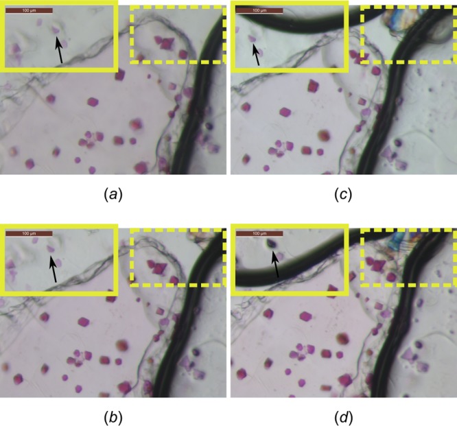
HwBR crystals grown in LCP in an opened in situ plate at room temperature (60–80% humidity) (a) before opening, (b) 4 h after opening, (c) 8 h after opening, and (d) 26 h after opening. Note that both glass plates were removed, exposing the inner Mylar film sandwich. This mimics the situation where an in situ well is mounted at the beam. Precipitant solution surrounding the mesophase bolus only slightly diminishes (i.e., dries out) within the first 4 h, whereas a pronounced effect is noticeable after 8 and 26 h (solid frames). Due to a concentration effect of the precipitant solution, salt crystals may start forming (dashed frames) after 4 h. Crystals embedded in the monoolein bolus are macroscopically not affected within 26 h, indicating that the lipid phase keeps crystals hydrated as long as it is surrounded by precipitant solution. Accordingly, crystals at the edge of the bolus may start to disappear or shift position, in the case the precipitant solution vanishes (compare arrows). Precipitant solution contained 8% (v/v) Tacsimate pH 7 and 20% (v/v) PEG 3350. Note that the effects mentioned above strongly depend on bolus and precipitant volumes as well as on the precipitant composition. Spacer thickness was 144 μm. Volumes of mesophase and precipitant solution were 200 nL and 1 μL, respectively. Scale bar is 100 μm.
Mylar in situ plates are very convenient to handle (Note S3). For instance, upon opening the plates by easily cutting the outer seal with a scalpel, several wells can then be isolated and mounted at a time (Supplementary Methods). Sections of the inner sandwich that are not required for immediate use are placed back into the outer glass sandwich and sealed again for long-term storage at the temperature at which the crystals grow (Supplementary Methods). Plates were designed to be handled both manually and by a robot. The work reported here was performed using a Gryphon LCP robot (Art Robbins Instruments; Sunnyvale, USA) with no changes to the existing protocol. As is the case with IMISX plates, Mylar in situ plates are transparent and can be imaged with a microscope under bright-field and polarized light (Figure 4) as well as UV light (Figure S4), facilitating the identification of protein crystals, especially small initial crystal hits or colorless crystals. Crystallization conditions obtained from glass plates translated almost exactly to Mylar in situ plates. Also, similar hit rate and crystal size and frequency were observed with the two plate types.
Figure 4.
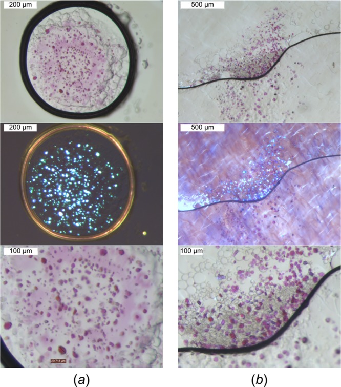
Comparison of crystal growth in the LCP. Crystals of bacteriorhodopsin HwBR are shown as grown on (a) standard glass plates and (b) Mylar in situ plates. (Top panel) Mesophase boluses under bright-field light. (Middle panel) Crystals shine brightly under cross-polarized light. (Bottom panel) Close-up views show no significant differences in crystal shape and size.
2.3. Holders for High-Throughput Screening and Routine Data Collection
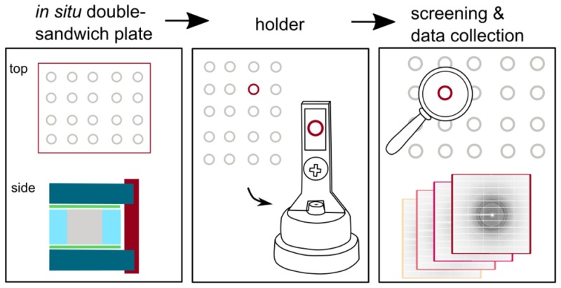
In order to facilitate and automate screening and data collection, we have developed a variety of holders, which were designed in a 3D program suited for 3D printing (Supplementary Methods). Printer files are available on request, so that users can print their own holders at a 3D printer of their convenience. These files are ready-to-use, as the designs have been optimized with respect to printing time, material consumption, orientation on the printer’s base level, and the use of supports and rafts. When 3D printed, all holders can easily be preassembled in large quantities (Supplementary Methods), allowing for an integrated, robust, and reproducible approach when mounting wells. For a quick and easy selection of the best holder for a particular project and setup, please refer to Figure 5.
Figure 5.

Holder-selection scheme. Goniometer-based holders can be used for either screening (with limited suitability for data collection; refer to text) or data collection. Some holders can be used for measurements at room temperature (RT) or under cryogenic (cryo) conditions. Adapter-based holders can be used for screening and data collection at RT or under cryo conditions. Translation stages might be necessary for full coverage of a particular holder. Depending on the number of wells that are supposed to be analyzed, holders can hold patches of Mylar film sandwiches containing up to 96 in situ wells at a time. Please refer to the indicated figures in the main text.
Holders for Data Collection
Single-well holders clamp a single well at a time (Figure 6a,b). The room-temperature holder features a full frame for stability, while the cryo-holder has no frame in order to reduce the interference with the cryo stream. Both holders come with supports at the feet for added stability. The base part and lid are connected by screw and nut, with the screw going through both holes. A bulge at the lower end of the lid allows for a clamping effect when the holder is closed (Figure 6e). For a similar effect, the hole is moved down in the case of the cryo holder. The goniometer base is the same for both holders. A CrystalCap SPINE base (SPINE base) from Hampton Research (Aliso Viejo, USA) was used together with a 3D-printed adapter that can hold both holders (Figure 6c). A slit in the adapter is off-centered (Figure 6d), so that the film sandwich, which holds the crystals, sits in the center of the SPINE base once the holder is fully assembled. By default, crystals are then in or close to the plane of focus of the on-axis microscopes found at synchrotrons.
Figure 6.
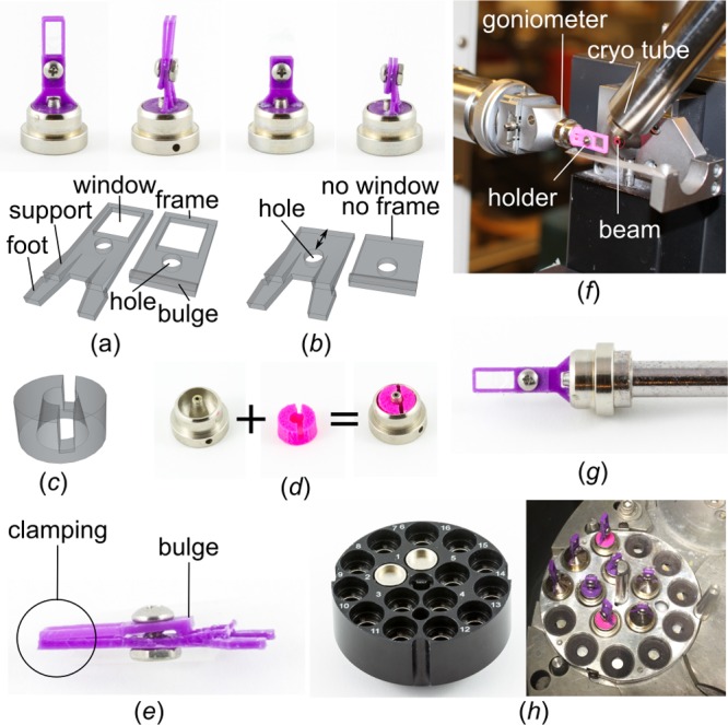
Design features of single-well holders for data collection. (a) The holder for room temperature measurements has a frame. Base part (left) and lid (right) are connected by screw and nut. (b) The holder for measurements under cryogenic conditions comes without a frame. The holes in base part (left) and lid (right) are moved down. (c) 2D graphic of the SPINE-base adapter. (d) The adapter sits in the SPINE base and can hold both holders. (e) A bulge at the lower end of the lid allows for clamping the film sandwich. (f) Use of the room-temperature holder at a home source. (g) Holders can be flash-cooled in liquid nitrogen and (h) stored and shipped in a Universal V1-Puck container.
Importantly, both single-well holders are small enough to be used at a synchrotron and at a home source (Figure 6f), where space is usually limited. Moreover, both holder types can withstand liquid nitrogen (Figure 6g), which allows for optimal storage of crystals in whole wells in a Dewar until beamtime becomes available. In this study, whole wells mounted onto single-well holders were shipped in Unipucks (Figure 6h) to the GM/CA beamline at the Advanced Photon Source (APS; Lemont, IL, USA) synchrotron, where they proved to be fully compatible with the automounter system (Supplementary Movie). For data collection at 100 K, the holders in the SPINE bases were automatically transferred from liquid nitrogen to the goniometer, and the crystals in the wells remained in the cryo-stream, essentially as would crystals in a loop.
The possibility to store and ship wells under cryo-conditions simplifies sample handling, tremendously increases the amount of crystals that can be brought to a synchrotron for high-throughput screening, and takes advantage of extending the lifetime of crystals compared to room-temperature measurements, reducing the number of crystals required for collecting a full data set. Compatibility with an automounter system is a prerequisite for routine operations, enabling remote access to in situ samples at synchrotron sources.
Holders for High-Throughput Screening and Data Collection at Room Temperature
A variety of goniometer-based screening holders for 4, 24, and 96 wells can be used to rapidly screen crystallization conditions at room temperature. Screening holders are lightweight and can be easily and quickly attached to any goniometer. The 4-well holder comes with a frame to keep a row of 4 in situ wells in place (Figure 7a). Note that the 4-well holder can be too big for some in-house X-ray sources. However, at synchrotrons (and nowadays also some home sources) there is enough space in all directions. Larger patches of in situ film sandwiches (with up to 24 or 96 wells) can be attached quickly and reversibly to screening holders for 24 or 96 wells (Figure 7b,c) by using a standard glue stick (Supplementary Methods).
Figure 7.
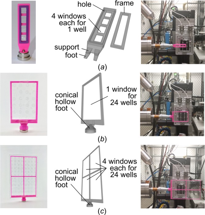
Design features of goniometer-based holders for screening at room temperature. (a) Holder for strips of 4 in situ wells. A frame clamps the film sandwich tight and can be easily removed using a wire. (b) Holder for up to 24 in situ wells. (c) Holder for up to 96 in situ wells with 4 windows that each accommodate 24 wells.
All goniometer-based screening holders are ideal for rapidly screening the diffraction quality of crystals in the different wells. While the 4-well holder can be supported on both GM/CA beamlines without an additional translation stage, the 24- and 96-well holders require one in order to move the goniometer vertically and horizontally, thereby covering all of the wells. For the larger 96-well holder, the GM/CA facility can handle approximately 6 rows and the full horizontal translation on one beamline and about 6 rows and 6 columns on the other beamline, where a vacuum tube prevents further horizontal translation. Within limitations, these holders also allow the collection of diffraction data. However, the axis of rotation will not be aligned with the center of the sample, which hampers optimally centering crystals that are far off the area that would hold crystals in a standard loop. Thus, it is highly probable that upon rotation of crystals during data collection particularly small crystals will eventually move out of the plane of focus. In the worst case, a crystal is not hit by the beam anymore, while it is still stable and would produce good diffraction-quality data.
A set of modified screening holders for 1, 4, 24, 48, and 96 wells at a time (Figure 8a–e) makes the screening holders more versatile. Here, the feet are planar and fit into an adapter (Figure 8f) that was developed by the GM/CA team at the APS and thus will henceforth be referred to as GM/CA adapter. For proper use, the GM/CA adapter includes an additional translation stage that must be attached to the goniometer. As it comes with submicron-level motion control, allowing for centering any crystal in the bolus, screening holders with flat feet can be used for rapid screening as well as for data collection. Note that theoretically any adapter can be used that can hold plates of different thicknesses and that fits over the goniometer’s normal sample holder. If necessary, users of the Mylar in situ method might want to work with their individual beamlines to implement a suitable translation stage. Also, a combination of holders with a robotic arm is conceivable.
Figure 8.
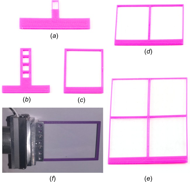
Design features of GM/CA adapter-based holders for screening and data collection at room temperature (and also under cryogenic conditions when using the single-well holder). A flat foot is characteristic of all holders that are to be clamped into the GM/CA adapter or any other adapter that can hold plates of varying thicknesses and comes with a fine-motor translation stage. (a) Single-well holder. (b) Holder for up to 4 in situ wells. (c) Holder for up to 24 in situ wells. (d) Holder for up to 48 in situ wells with 2 windows of 24 wells each. (e) Holder for up to 96 in situ wells with 4 windows of 24 wells each. (f) GM/CA adapter clamping a 48-well holder.
2.4. Flexible Usage of the Mylar In Situ Method
Besides growing crystals in situ, another approach to circumvent crystal harvesting is to transfer crystallization samples en masse to a chip with windows that are X-ray transparent.20,31 Similarly, another way to benefit from our technology is to transfer crystals that have been grown in other setups or assemblies, such as hanging drop, sitting drop, or batch crystallization, onto Mylar in situ plates. Here, we used the soluble protein myoglobin as a model protein. Myoglobin is the iron- and oxygen-binding pigment found in abundance in the muscle tissue of mammals, where it is also responsible for the characteristic red color. The prosthetic group heme in myoglobin can reversibly bind molecular oxygen and carbon monoxide, CO. In this study, sperm whale myoglobin (SWMb) crystals were grown in batch mode in glass vials under CO atmosphere (Figure 9a,b). SWMb-CO crystals were transferred onto Mylar in situ plates by pipetting (Figure 9c,d) and shipped to the APS synchrotron ahead of data collection (Note S4). At the beamline, plates were opened, wells were mounted, and immediately flash-frozen for 100 K measurements.
Figure 9.
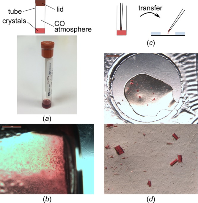
Sample delivery of crystals to synchrotrons using Mylar in situ plates. (a) SWMb-CO crystals have been grown in batch in a glass tube under CO atmosphere. (b) After 7–14 d, the tube solution has a high crystal density, and crystals were (c) transferred onto in situ plates by pipetting. (d) Drops of 1–2 μL were transferred per well (top panel). Crystal density can be adjusted as needed (bottom panel).
Any sample transfer requires pipetting steps, inevitably bearing the risk of damaging the sample. However, in our experience even very sensitive thin plate-like crystals could be transferred without macroscopic damage if the pipetting step was performed gently. In other cases, where crystals grown in clusters typically lead to complex diffraction patterns, we intentionally separated crystals during the transfer step, facilitating data collection on isolated crystal-cluster fragments. Moreover, for cryo-measurements, various cryo-protectants can be tested easily, as well. Finally, in order to minimize the number of raw diffraction images with complex diffraction patterns stemming from crystals that lie on top of each other, crystal density can be adjusted depending on the volume transferred per well. For more delicate samples that pipetting cannot handle, either standard glass capillaries or X-ray capillaries known from the counterdiffusion in situ technique32,33 should work in order to transfer crystals. Also, acoustic droplet ejection, where low volumes are moved via ultrasound waves and which has been used to transfer protein crystals onto data-collection media such as pin-mounted micromeshes,34 is a method worth looking into.
Recently, an in situ approach has been used to grow crystals of soluble proteins via vapor-diffusion and batch modes.7 The Mylar in situ method should be easily adaptable to both modes with only minor modifications.
2.5. Protein Structures under Cryogenic Conditions (100 K)
Lysozyme Data As Quality Control
While the LCP method was designed for use with membrane proteins, it is also compatible with water-soluble proteins. To develop and evaluate the Mylar in situ method and to check the quality of crystals grown in situ, we used the water-soluble protein HEWL as a model protein. HEWL is easy to handle, commercially available, and produces crystals that diffract to high resolution within a few hours (Supplementary Methods) under in meso conditions (Table S1).35 Crystals were set up on Mylar in situ plates and shipped to the GM/CA beamline at the APS synchrotron ahead of data collection. At the beamline, plates were opened, and wells were mounted and immediately flash-frozen for 100 K measurements. A full diffraction data set was collected in oscillation geometry from a single crystal (grown in space group P43212 with 90° of data required). The data collected under cryo-conditions allowed structure determination to 1.7 Å resolution; the resulting model was refined to Rwork and Rfree values of 0.16 and 0.21, respectively (Table S2). The final structure agrees well with a HEWL structure solved under similar conditions using the IMISX method (PDB ID: 5D5C; ref (10)) (Cα root-mean-square deviation [RMSD] of 0.21 Å). The electron density map revealed the presence of one polyethylene glycol (PEG) molecule, one acetate ion, several chloride ions, and a sodium ion octahedrally coordinated by the backbone carbonyl oxygen atoms of Ser60, Cys64, and Arg73, the oxygen Oγ of Ser72, and two water molecules. Most importantly, no effects were noticed from the Mylar film, the spacers’ adhesive, or the presence of nail polish on crystal growth and stability, diffraction quality, or the electron density map, indicating that Mylar in situ plates are well suited for general protein crystallization and structure determination.
Mass Transfer of Myoglobin Crystals
SWMb-CO crystals were transferred onto Mylar in situ plates as described above. Under cryogenic conditions, a full diffraction data set was collected from a single crystal grown in space group P6 (60° of data required) in oscillation geometry. The data collected under cryo-conditions allowed structure determination to 1.7 Å resolution; the resulting model was refined to Rwork and Rfree values of 0.18 and 0.22, respectively (Tables S1–2). The final structure agrees well with another structure obtained under similar conditions (PDB ID: 3E55, wild-type protein, space group P21; ref (99)). The corresponding electron density map is of high quality and revealed the presence of the iron-containing prosthetic group heme bound to CO, several sulfate ions, and two chloride ions. Most importantly, we noticed how easily and quickly Mylar in situ sandwich plates can be used as sample delivery system for other crystals, such as crystals of soluble proteins and/or crystals not grown in situ.
Structure of Bacteriorhodopsin from Haloquadratum walsbyi
Bacteriorhodopsin from Haloquadratum walsbyi (HwBR) is a light-driven proton pump with 7 transmembrane α-helices.28 HwBR is a good model membrane protein, as it is colored and can be produced in E. coli in sufficient quantities.29 In meso crystals grow as hexagonal flat plates (Tables S1–2) that are mechanically sensitive and easily break during harvesting, making an in situ approach for this type of crystals particularly useful. Crystals were grown on Mylar in situ plates and shipped to the GM/CA beamline at the APS synchrotron ahead of data collection. At the beamline, plates were opened, wells were mounted, and immediately flash-frozen for 100 K measurements. Full data sets were collected, and the structure at 100 K could be solved to 2.1 Å with high quality parameters and was refined with values of Rwork and Rfree of 0.21 and 0.23, respectively (Table S2). HwBR crystals used in this study pack in space group C2 (180° of data needed), and the solved structure agrees well with another structure obtained under similar conditions (PDB ID: 5ITE; to be published) (Cα RMSD of 0.23 Å over 689 residues) (Figure 10). The corresponding electron density map is of high quality and revealed the presence of the cofactor retinal bound to Lys224 (Figure 10c), several monoolein lipids, and water molecules.
Figure 10.
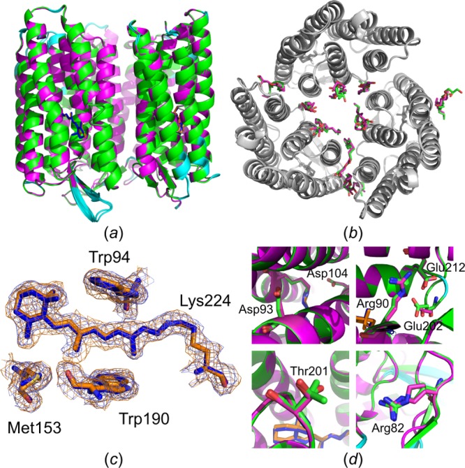
Structure alignment based on sequence alignment with subsequent optimizing fit using the Cα positions for HwBR. (a) Structural alignment of HwBR structures solved under cryogenic conditions: 5ITE harvested from glass plates (green, retinal in blue) and in situ structure from this study (magenta, retinal in orange). Residues with a Cα RMSD > 0.2 Å are highlighted in cyan. Retinal molecules are shown as sticks. (b) Top view of HwBR structures in gray. Monooleins are shown as sticks with the color code as in (a). (c) Residues of the retinal binding site are shown as sticks. 2F0 – Fc electron density maps in blue (5ITE) and orange (in situ structure) are contoured at 1σ. (d) Residues involved in the proton translocation pathway of HwBR are shown in stick representation (carbon green and magenta; oxygen red; nitrogen blue).
2.6. Data Collection at Room Temperature (293 K)
Room-temperature measurements do not work well with small, weakly diffracting, and/or radiation-sensitive crystals,36,37 as was the case here with HwBR crystals. In such circumstances, it is advisable to perform in situ measurements at the standard cryogenic temperature of 100 K (see above). However, on a more general note regarding in meso crystallography, it was easier to spot even very small crystals in the essentially optically transparent mesophase at 293 K in contrast with comparable measurement at 100 K, where the mesophase has a tendency to turn turbid. This allowed rapidly choosing crystals with the on-axis camera at the beamline and eliminated the need to perform diffraction raster scanning to locate crystals, which is time-consuming and generates a multitude of images that need to be analyzed.
In general, the flat profile of in situ wells allows for data collection over a very wide angular range. However, at room temperature, radiation damage severely limits the amount of data that can be collected from a single crystal.36,37 Thus, the data-collection strategy at 293 K included collecting small angular wedges of relatively radiation damage-free data from individual crystals. By repeating this process on randomly oriented crystals, a complete data set of high quality can be produced by merging many small data wedges from a multitude of randomly oriented crystals (Supplementary Methods). For example, using HEWL crystals we found that usually only the first 10° of data (in rare cases, such as big crystals, up to 20° of data) are suitable for use in structure determination by molecular replacement and refinement. Accordingly, for each crystal, a total of 10° of data were collected by rotation, and data from 9 crystals (with nonredundant data) were then processed and merged. Crystals diffracted to 2.0 Å resolution, and the structure was refined with Rwork and Rfree values of 0.15 and 0.20, respectively (Table S2). For details on the HEWL structure at the two different temperatures, please see Note S5. Room-temperature structures can help to shed light on mechanistic questions, such as protein activation, ligand binding, or protein-complex formation, making the Mylar in situ method particularly valuable for studying these and other phenomena. Note that for the small HwBR crystals radiation damage was too severe at room temperature to allow useful data sets to be collected using the rotation method.
2.7. High-Throughput Screening at Room Temperature
The success of protein-structure determination by crystallography relies on screening a large number of crystallization conditions. On many occasions, particularly during the early stages of optimizing crystallization, any project would benefit from a screening approach that immediately reports back on the diffraction quality of crystals despite the limited crystal size (assuming crystals are at least big enough to be detectable and assessable with a microbeam). An integrated approach of Mylar in situ plates with an exhaustive set of screening holders developed in this study (see above) allows for rapidly screening up to 96 crystallization conditions at a time in order to verify the proteinaceous nature of crystals and to assess their diffraction quality as a function of precipitant composition. Also, the quality of several crystals per crystallization condition can be assessed easily. This is helpful, given the experience that often not all crystals in one well are of equal quality. For instance, big crystals with an increased diffraction volume often show a better signal-to-noise ratio than small crystals. Thus, it remains to be studied how the optimization process of crystallization conditions might be influenced by the possibility to screen and optimize for diffraction quality using initial crystal hits consisting of a few microcrystals prior to optimizing crystal size (with an apparently additional positive effect on the signal-to-noise ratio) in contrast to the standard reverse approach. Note that wells of opened in situ sandwiches after removal of the glass plates (Figure 3) lost less than 10% of water over the first 6 h under X-ray exposure (Figure S5).
3. Outlook
Synchrotrons make in situ structural studies of proteins easier, faster, and more successful. For instance, developments such as attenuated microbeams,38,39 faster detectors,40,41 rastering and/or vectoring data-collection software,42 or multi-crystal data-collection software43,44 aim at automating and facilitating structural work. On top of that, this and other in situ methods would benefit even more from new hardware and software developments such as, among others, goniometers that can undergo substantial movements along all axes; a cryo-stream that moves as synchronized to the goniometer; a chamber to open in situ plates and treat isolated wells at a fixed relative humidity; a hutch humidifier or environment control chamber (regulating temperature and humidity) around the goniometer; software that simultaneously with data collection of small wedges merges user-selected data sets in order to report back on the completeness of the data; and software that automatically localizes and shoots crystals. The Mylar in situ method is currently also extended to serial crystallography at synchrotrons and to XFEL measurements. For serial crystallography at synchrotrons, whole wells with a high density of small crystals are rastered at a high frequency, which generates thousands of images per well and enables hit rates of 40–50%. While for XFEL measurements fixed-target crystallography chips with protein crystals of known position in the device facilitate the collection of data sets,20−23 Mylar in situ plates require imaging, obliging the use of a suitable light-source for light-sensitive proteins. Nevertheless, the Mylar in situ method, particularly using goniometer-based holders, can be a very useful fixed-target sample-delivery technique, enabling crystal screening and data collection. In combination with imaging, high hit rates and acquisition of time-resolved information are conceivable.
4. Conclusion
The Mylar in situ method works reliably for soluble and membrane proteins grown in or transferred to Mylar in situ plates and allows for the determination of high-quality protein structures at high resolutions. It is simple and easy to use, inexpensive, versatile, and robust. Moreover, it promises automated crystal imaging, screening, and goniometer-based X-ray diffraction data-collection of protein structural studies at room temperature and under cryogenic conditions to become faster and more routine. The method is currently used regularly and with great success in our hands and that of collaborators. Crystals of even such challenging targets as G protein-coupled receptors (GPCRs) have been grown on Mylar in situ plates under conditions established on standard glass plates. Mylar in situ plates can be assembled easily in the lab from a handful of commercially available materials. Upon request, the authors will send out printer files for the holders described. Possibilities to commercialize the Mylar in situ method are currently considered. Taken together, the Mylar in situ method is a valuable tool for the in situ analysis of soluble and membrane proteins by providing a facile route to crystal structures and potentially also to time-resolved crystallography of soluble and membrane proteins.
Acknowledgments
We are grateful to Frank Sicheri, P. Lynne Howell, Emil F. Pai, Gilbert G. Privé, and Raymon Julien (all University of Toronto) for providing access to X-ray home sources. We thank the MADLab and the Gerstein Library, in particular Erica Lenton and Michael Spears (University of Toronto), for admission to the 3D printing facility. We also thank Yang Shen (University of Toronto) for help with purifying SWMb and growing SWMb-CO crystals, as well as John S. Olson (Rice University, USA) for providing plasmid pMb413a. We also thank Allison Trnka (Saunders, USA) for supplying us with various spacers and Jeff Sansome from the Machine Shop (University of Toronto) for advice with clamping. This research used resources of the Advanced Photon Source, a U.S. Department of Energy (DOE) Office of Science User Facility operated for the DOE Office of Science by Argonne National Laboratory under Contract No. DE-AC02-06CH11357. We particularly thank the staff at the GM/CA beamline. For fruitful discussions and carefully reading the manuscript we are grateful to Emil F. Pai (University of Toronto). This work was supported by a Research Fellowship from the German Research Foundation (DFG) to J.B. (BR 5124/1-1) and by the Canada Excellence Research Chair program (to O.P.E.). O.P.E. holds the Anne and Max Tanenbaum Chair in Neuroscience at the University of Toronto.
Supporting Information Available
The Supporting Information is available free of charge on the ACS Publications website at DOI: 10.1021/acs.cgd.6b00950.
Materials and methods, supplementary notes, supplementary results (figures; crystallization and crystal information; data collection and refinement statistics), supplementary references (PDF)
Whole wells mounted onto single-well holders shipped in Unipucks were proven to be fully compatible with the automounter system (MOV)
Accession Codes
Coordinates and structure factors have been deposited in the Protein Data Bank under accession codes 5KKH (in situ structure of HwBR at 100 K), 5KKI (in situ structure of HEWL at 100 K), 5KKJ (in situ structure of HEWL at 293 K), and 5KKK (in situ structure of SWMb-CO at 100 K).
Author Contributions
J.B. and O.P.E. designed the research and wrote the manuscript. J.B. performed the research. V.K. assisted with plate and holder design. A.K. generated SWMb-CO crystals. J.B., A.R.B., and W.O. solved crystal structures. D.J.K. and C.M.O. helped with data collection.
The authors declare no competing financial interest.
Supplementary Material
References
- Giegé R.; Sauter C. HFSP J. 2010, 4, 109. 10.2976/1.3369281. [DOI] [PMC free article] [PubMed] [Google Scholar]
- Joachimiak A. Curr. Opin. Struct. Biol. 2009, 19, 573. 10.1016/j.sbi.2009.08.002. [DOI] [PMC free article] [PubMed] [Google Scholar]
- Beteva A.; Cipriani F.; Cusack S.; Delageniere S.; Gabadinho J.; Gordon E. J.; Guijarro M.; Hall D. R.; Larsen S.; Launer L.; Lavault C. B.; Leonard G. A.; Mairs T.; McCarthy A.; Meyer J.; Mitchell E.; Monaco S.; Nurizzo D.; Pernot P.; Pieritz R.; Ravelli R. G. B.; Rey V.; Shepard W.; Spruce D.; Stuart D. I.; Svensson O.; Theveneau P.; Thibault X.; Turkenburg J.; Walsh M.; McSweeney S. M. Acta Crystallogr., Sect. D: Biol. Crystallogr. 2006, 62, 1162. 10.1107/S0907444906032859. [DOI] [PubMed] [Google Scholar]
- Garman E. F. Science 2014, 343, 1102. 10.1126/science.1247829. [DOI] [PubMed] [Google Scholar]
- Aller P.; Sanchez-Weatherby J.; Foadi J.; Winter G.; Lobley C. M.; Axford D.; Ashton D.; Bellini D.; Brandao-Neto J.; Culurgioni S.; Douangamath A.; Duman R.; Evans G.; Fisher S.; Flaig R.; Hall D. R.; Lukacik P.; Mazzorana M.; McAuley K. E.; Mykhaylyk V.; Owen R. L.; Paterson N. G.; Romano P.; Sandy J.; Sorensen T.; von Delft F.; Wagner A.; Warren A.; Williams M.; Stuart D. I.; Walsh M. A. Methods Mol. Biol. 2015, 1261, 233. 10.1007/978-1-4939-2230-7_13. [DOI] [PubMed] [Google Scholar]
- Bingel-Erlenmeyer R.; Olieric V.; Grimshaw J. P. A.; Gabadinho J.; Wang X.; Ebner S. G.; Isenegger A.; Schneider R.; Schneider J.; Glettig W.; Pradervand C.; Panepucci E. H.; Tomizaki T.; Wang M.; Schulze-Briese C. Cryst. Growth Des. 2011, 11, 916. 10.1021/cg101375j. [DOI] [Google Scholar]
- Axford D.; Aller P.; Sanchez-Weatherby J.; Sandy J. Acta Crystallogr., Sect. F: Struct. Biol. Commun. 2016, 72, 313. 10.1107/S2053230X16004386. [DOI] [PMC free article] [PubMed] [Google Scholar]
- Cipriani F.; Röwer M.; Landret C.; Zander U.; Felisaz F.; Márquez J. A. Acta Crystallogr., Sect. D: Biol. Crystallogr. 2012, 68, 1393. 10.1107/S0907444912031459. [DOI] [PubMed] [Google Scholar]
- Huang C.-Y.; Olieric V.; Ma P.; Panepucci E.; Diederichs K.; Wang M.; Caffrey M. Acta Crystallogr., Sect. D: Biol. Crystallogr. 2015, 71, 1238. 10.1107/S1399004715005210. [DOI] [PMC free article] [PubMed] [Google Scholar]
- Huang C.-Y.; Olieric V.; Ma P.; Howe N.; Vogeley L.; Liu X.; Warshamanage R.; Weinert T.; Panepucci E.; Kobilka B.; Diederichs K.; Wang M.; Caffrey M. Acta Crystallogr., Sect. D: Biol. Crystallogr. 2016, 72, 93. 10.1107/S2059798315021683. [DOI] [PMC free article] [PubMed] [Google Scholar]
- Pinker F.; Brun M.; Morin P.; Deman A.-L.; Chateaux J.-F.; Oliéric V.; Stirnimann C.; Lorber B.; Terrier N.; Ferrigno R.; Sauter C. Cryst. Growth Des. 2013, 13, 3333. 10.1021/cg301757g. [DOI] [Google Scholar]
- Heymann M.; Opthalage A.; Wierman J. L.; Akella S.; Szebenyi D. M. F.; Gruner S. M.; Fraden S. IUCrJ 2014, 1, 349. 10.1107/S2052252514016960. [DOI] [PMC free article] [PubMed] [Google Scholar]
- Perry S. L.; Guha S.; Pawate A. S.; Henning R.; Kosheleva I.; Srajer V.; Kenis P. J. A.; Ren Z. J. Appl. Crystallogr. 2014, 47, 1975. 10.1107/S1600576714023322. [DOI] [PMC free article] [PubMed] [Google Scholar]
- Stroock A. D.; Dertinger S. K. W.; Ajdari A.; Mezić I.; Stone H. A.; Whitesides G. M. Science 2002, 295, 647. 10.1126/science.1066238. [DOI] [PubMed] [Google Scholar]
- Li L.; Fu Q.; Kors C.; Stewart L.; Nollert P.; Laible P.; Ismagilov R. Microfluid. Nanofluid. 2010, 8, 789. 10.1007/s10404-009-0512-8. [DOI] [PMC free article] [PubMed] [Google Scholar]
- Khvostichenko D. S.; Schieferstein J. M.; Pawate A. S.; Laible P. D.; Kenis P. J. Cryst. Growth Des. 2014, 14, 4886. 10.1021/cg5011488. [DOI] [PMC free article] [PubMed] [Google Scholar]
- Yadav M.; Gerdts C. J.; Sanishvili R.; Smith W. W.; Roach L. S.; Ismagilov R. F.; Kuhn P.; Stevens R. C. J. Appl. Crystallogr. 2005, 38, 900. 10.1107/S002188980502649X. [DOI] [PMC free article] [PubMed] [Google Scholar]
- Pineda-Molina E.; Daddaoua A.; Krell T.; Ramos J. L.; García-Ruiz J. M.; Gavira J. A. Acta Crystallogr., Sect. F: Struct. Biol. Commun. 2012, 68, 1307. 10.1107/S1744309112028540. [DOI] [PMC free article] [PubMed] [Google Scholar]
- Maeki M.; Yoshizuka S.; Yamaguchi H.; Kawamoto M.; Yamashita K.; Nakamura H.; Miyazaki M.; Maeda H. Anal. Sci. 2012, 28, 65. 10.2116/analsci.28.65. [DOI] [PubMed] [Google Scholar]
- Mueller C.; Marx A.; Epp S. W.; Zhong Y.; Kuo A.; Balo A. R.; Soman J.; Schotte F.; Lemke H. T.; Owen R. L.; Pai E. F.; Pearson A. R.; Olson J. S.; Anfinrud P. A.; Ernst O. P.; Miller R. J. D. Struct. Dyn. 2015, 2, 054302. 10.1063/1.4928706. [DOI] [PMC free article] [PubMed] [Google Scholar]
- Oghbaey S.; Sarracini A.; Ginn H. M.; Pare-Labrosse O.; Kuo A.; Marx A.; Epp S. W.; Sherrell D. A.; Eger B. T.; Zhong Y.; Loch R.; Mariani V.; Alonso-Mori R.; Nelson S.; Lemke H. T.; Owen R. L.; Pearson A. R.; Stuart D. I.; Ernst O. P.; Müller-Werkmeister H. M.; Miller R. J. D. Acta Cryst. D. Biol. Crystallogr. 2016, 72, 944. 10.1107/S2059798316010834. [DOI] [PMC free article] [PubMed] [Google Scholar]
- Zarrine-Afsar A.; Barends T. R.; Müller C.; Fuchs M. R.; Lomb L.; Schlichting I.; Miller R. J. Acta Crystallogr., Sect. D: Biol. Crystallogr. 2012, 68, 321. 10.1107/S0907444911055296. [DOI] [PubMed] [Google Scholar]
- Roedig P.; Vartiainen I.; Duman R.; Panneerselvam S.; Stübe N.; Lorbeer O.; Warmer M.; Sutton G.; Stuart D. I.; Weckert E.; David C.; Wagner A.; Meents A. Sci. Rep. 2015, 5, 10451. 10.1038/srep10451. [DOI] [PMC free article] [PubMed] [Google Scholar]
- Landau E. M.; Rosenbusch J. P. Proc. Natl. Acad. Sci. U. S. A. 1996, 93, 14532. 10.1073/pnas.93.25.14532. [DOI] [PMC free article] [PubMed] [Google Scholar]
- Caffrey M. Acta Crystallogr., Sect. F: Struct. Biol. Commun. 2015, 71, 3. 10.1107/S2053230X14026843. [DOI] [PMC free article] [PubMed] [Google Scholar]
- Caffrey M.; Cherezov V. Nat. Protoc. 2009, 4, 706. 10.1038/nprot.2009.31. [DOI] [PMC free article] [PubMed] [Google Scholar]
- Cherezov V. Curr. Opin. Struct. Biol. 2011, 21, 559. 10.1016/j.sbi.2011.06.007. [DOI] [PMC free article] [PubMed] [Google Scholar]
- Sudo Y.; Ihara K.; Kobayashi S.; Suzuki D.; Irieda H.; Kikukawa T.; Kandori H.; Homma M. J. Biol. Chem. 2011, 286, 5967. 10.1074/jbc.M110.190058. [DOI] [PMC free article] [PubMed] [Google Scholar]
- Hsu M.-F.; Fu H.-Y.; Cai C.-J.; Yi H.-P.; Yang C.-S.; Wang A. H.-J. J. Biol. Chem. 2015, 290, 29567. 10.1074/jbc.M115.685065. [DOI] [PMC free article] [PubMed] [Google Scholar]
- In Handbook of Biological Confocal Microscopy, 3rd ed.; Pawley J. B., Ed.; Springer Science+Business Media: New York, 2006; Chapter 18, pp 371. [Google Scholar]
- Murray T. D.; Lyubimov A. Y.; Ogata C. M.; Vo H.; Uervirojnangkoorn M.; Brunger A. T.; Berger J. M. Acta Crystallogr., Sect. D: Biol. Crystallogr. 2015, 71, 1987. 10.1107/S1399004715015011. [DOI] [PMC free article] [PubMed] [Google Scholar]
- Gavira J. A.; Toh D.; Lopéz-Jaramillo J.; García-Ruíz J. M.; Ng J. D. Acta Crystallogr., Sect. D: Biol. Crystallogr. 2002, 58, 1147. 10.1107/S0907444902006959. [DOI] [PubMed] [Google Scholar]
- Ng J. D.; Gavira J. A.; García-Ruíz J. M. J. Struct. Biol. 2003, 142, 218. 10.1016/S1047-8477(03)00052-2. [DOI] [PubMed] [Google Scholar]
- Soares A. S.; Engel M. A.; Stearns R.; Datwani S.; Olechno J.; Ellson R.; Skinner J. M.; Allaire M.; Orville A. M. Biochemistry 2011, 50, 4399. 10.1021/bi200549x. [DOI] [PMC free article] [PubMed] [Google Scholar]
- Caffrey M.; Cherezov V. Nat. Protoc. 2009, 4, 706. 10.1038/nprot.2009.31. [DOI] [PMC free article] [PubMed] [Google Scholar]
- Tomita A.; Sato T.; Ichiyanagi K.; Nozawa S.; Ichikawa H.; Chollet M.; Kawai F.; Park S.-Y.; Tsuduki T.; Yamato T.; Koshihara S.-y.; Adachi S.-i. Proc. Natl. Acad. Sci. U. S. A. 2009, 106, 2612. 10.1073/pnas.0807774106. [DOI] [PMC free article] [PubMed] [Google Scholar]
- Holton J. M. J. Synchrotron Radiat. 2009, 16, 133. 10.1107/S0909049509004361. [DOI] [PMC free article] [PubMed] [Google Scholar]
- Warkentin M.; Hopkins J. B.; Badeau R.; Mulichak A. M.; Keefe L. J.; Thorne R. E. J. Synchrotron Radiat. 2013, 20, 7. 10.1107/S0909049512048303. [DOI] [PMC free article] [PubMed] [Google Scholar]
- Axford D.; Owen R. L.; Aishima J.; Foadi J.; Morgan A. W.; Robinson J. I.; Nettleship J. E.; Owens R. J.; Moraes I.; Fry E. E.; Grimes J. M.; Harlos K.; Kotecha A.; Ren J.; Sutton G.; Walter T. S.; Stuart D. I.; Evans G. Acta Crystallogr., Sect. D: Biol. Crystallogr. 2012, 68, 592. 10.1107/S0907444912006749. [DOI] [PMC free article] [PubMed] [Google Scholar]
- Yoder D. W.; Sanishvili R.; Vogt S.; Xu S.; Makarov O.; Benn R.; Corcoran S.; Fischetti R. F. AIP Conf. Proc. 2010, 1234, 419. 10.1063/1.3463229. [DOI] [Google Scholar]
- Broennimann C.; Eikenberry E. F.; Henrich B.; Horisberger R.; Huelsen G.; Pohl E.; Schmitt B.; Schulze-Briese C.; Suzuki M.; Tomizaki T.; Toyokawa H.; Wagner A. J. Synchrotron Radiat. 2006, 13, 120. 10.1107/S0909049505038665. [DOI] [PubMed] [Google Scholar]
- Dinapoli R.; Bergamaschi A.; Henrich B.; Horisberger R.; Johnson I.; Mozzanica A.; Schmid E.; Schmitt B.; Schreiber A.; Shi X.; Theidel G. Nucl. Instrum. Methods Phys. Res., Sect. A 2011, 650, 79. 10.1016/j.nima.2010.12.005. [DOI] [Google Scholar]
- Cherezov V.; Hanson M. A.; Griffith M. T.; Hilgart M. C.; Sanishvili R.; Venugopalan N.; Stepanov S.; Fischetti R. F.; Kuhn P.; Stevens R. C. J. R. Soc. Interface 2009, 6, S587. 10.1098/rsif.2009.0142.focus. [DOI] [PMC free article] [PubMed] [Google Scholar]
- Pothineni S. B.; Venugopalan N.; Ogata C. M.; Hilgart M. C.; Stepanov S.; Sanishvili R.; Becker M.; Winter G.; Sauter N. K.; Smith J. L.; Fischetti R. F. J. Appl. Crystallogr. 2014, 47, 1992. 10.1107/S1600576714022730. [DOI] [PMC free article] [PubMed] [Google Scholar]
- Foadi J.; Aller P.; Alguel Y.; Cameron A.; Axford D.; Owen R. L.; Armour W.; Waterman D. G.; Iwata S.; Evans G. Acta Crystallogr., Sect. D: Biol. Crystallogr. 2013, 69, 1617. 10.1107/S0907444913012274. [DOI] [PMC free article] [PubMed] [Google Scholar]
Associated Data
This section collects any data citations, data availability statements, or supplementary materials included in this article.