Abstract
We describe an approach for the discrete and reversible assembly of tunable and actively deformable structures using modular building block parts for robotic applications. The primary technical challenge addressed by this work is the use of this method to design and fabricate low density, highly compliant robotic structures with spatially tuned stiffness. This approach offers a number of potential advantages over more conventional methods for constructing compliant robots. The discrete assembly reduces manufacturing complexity, as relatively simple parts can be batch-produced and joined to make complex structures. Global mechanical properties can be tuned based on sub-part ordering and geometry, because local stiffness and density can be independently set to a wide range of values and varied spatially. The structure's intrinsic modularity can significantly simplify analysis and simulation. Simple analytical models for the behavior of each building block type can be calibrated with empirical testing and synthesized into a highly accurate and computationally efficient model of the full compliant system. As a case study, we describe a modular and reversibly assembled wing that performs continuous span-wise twist deformation. It exhibits high performance aerodynamic characteristics, is lightweight and simple to fabricate and repair. The wing is constructed from discrete lattice elements, wherein the geometric and mechanical attributes of the building blocks determine the global mechanical properties of the wing. We describe the mechanical design and structural performance of the digital morphing wing, including their relationship to wind tunnel tests that suggest the ability to increase roll efficiency compared to a conventional rigid aileron system. We focus here on describing the approach to design, modeling, and construction as a generalizable approach for robotics that require very lightweight, tunable, and actively deformable structures.
Keywords: : discrete reconfigurable lattice assembly, morphing aerostructure, ultralight elastomeric cellular solid
Introduction
The ability to morph, or change shape, is desirable for a number of reasons in nature or in engineering, such as responding to varying external conditions,1 improving interaction with other bodies,2 or maneuvering in various media such as water3 or air.4 Soft robots typically achieve shape change through the compliance of their constituent material,5 which corresponds to materials with elastic moduli similar to those of soft biological materials, on the order of 104–109 Pa.6
Robinson and Davies7 describe three categories of robots: discrete, serpentine, and continuum. Trivedi et al.5 go further to differentiate between hard and soft continuum, based mainly on the robot's construction materials.
We introduce a new category of soft continuum robots based on low density and high specific stiffness cellular structures, made from high specific modulus constituent material such as carbon fiber-reinforced polymers (CFRP).
Many soft robots are defined by the use of elastomeric materials, whereas discretely assembled cellular composite structures allow for the design of tunable moduli ranging between those of engineering polymers, elastomers, and foams, all of which have orders of magnitude that are at a lower density than the comparable solid material. Our approach can result in ultralight heterogeneous continuum material behavior in one integrated structure.
Our approach is based on discrete lattice assembly, in which modular 2D elements mechanically link in 3D to form reversibly assembled composite lattices. This process is not limited by scale, and it enables disassembly and reconfiguration. These structures form cellular solids with properties that are governed by their constituent material and lattice geometry.8 Such engineered periodic lattices act as continuum meta-materials, analogous to naturally occurring cellular materials such as foams and sponges.9 These structures can be designed to have high specific stiffness and strength with behavior dominated by material stretching, or to have compliant and energy-absorbing behavior dominated by component bending.10 This approach allows a single robotic structure to express both “hard” and “soft” continuum behavior based on the tunable lattice geometry.
Shape changing for maneuvering and control is a central objective for many soft robots, many of which tend to be highly specific platforms.5 Analysis of these structures usually uses time and computation-intensive finite element analysis (FEA), which typically requires mesh triangulation of complex geometries.11 For highly deformable structures, the re-meshing iterations that are necessary for simulation can become burdensome.12 Modular designs attempt to reduce complexity through repetition of individual building blocks, such as modular elements containing fluidic elastomer actuators,13 and magnetic, self-assembling modular elastomeric cells.14
We leverage modularity to extend the field's work to develop extensible design, analysis, and assembly tools for making soft robotic systems. Prior work has shown that modularity in construction permits a description of the continuum as a series of beams and nodes, which can be used to create a voxel-based, tuned mass-spring lattice model to simulate the dynamics of highly deformable heterogeneous materials.15 In homogeneous, periodic volumes, the behavior of networks of Euler–Bernoulli beams can be used to efficiently model bulk material behavior.9 We use the description of these structures as networks of beams and show that boundary conditions and heterogeneous assemblies can be accurately modeled this way. We further show that having physical access to individual parts for testing and tuning of simplified macro-element models can provide highly accurate results.
In this work, a primary goal is to present a fabrication process using mass-produced, discretely assembled lattice elements that are capable of building at multiple scales.16 Manufacturing processes for soft robotics, such as complex mold fabrication and multi-step casting, can be time and labor intensive, sensitive to error, and scale limited.17,18 Inflatable robotic arms can be larger,19 and a wide variety of robots can be made by sewing patches of fabric together.20,21 Although this system can be scaled to large sizes, the complexity that arises for efficient design and repeatable manufacture of these types of robots becomes a challenge.
The work presented here contributes to the field of soft robotics by demonstrating a method for designing, analyzing, and building actively deformable elastic structures using modular, reconfigurable building-block elements, resulting in tunable heterogeneous behavior.
To ground these arguments, we use this method in a case study of a shape-changing wing that performs continuous span-wise twist deformation for roll actuation. The wing has high-performance aerodynamic characteristics while also being lightweight and simple to fabricate and repair due to its assembly method (Fig. 1). This soft robotic wing structure exhibits continuous deformation for aerodynamic control without conventional rigid control surfaces.
FIG. 1.
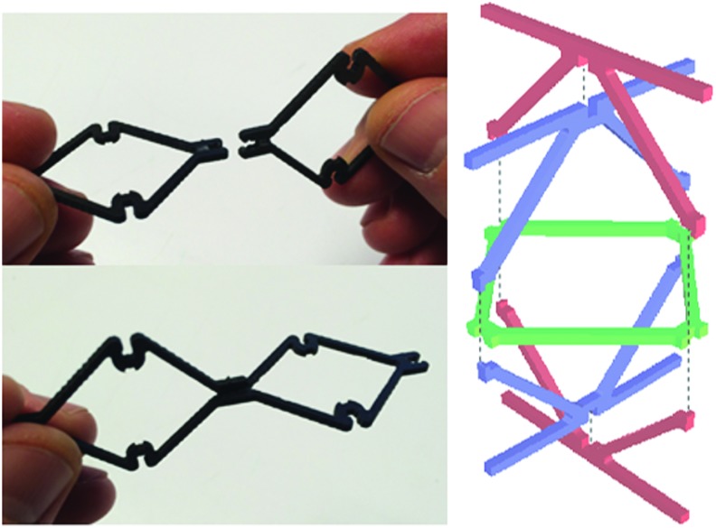
Construction of shape-changing structures from discrete lattice building-block elements. Several elements are shown with two joined together (top–left); multiple part types are joined together to form part of the overall structure (top–right); an early prototype of the overall structures with shape-changing geometry exhibited (bottom).
Methodology
Ultralight elastomeric cellular solids
Cellular solids are a relatively recent innovation in materials design, enabling access to previously inaccessible regions of the material property space, such as high strength and stiffness per weight at very low mass density. They are composed of an interconnected network of either beams or plates, which form the edges and faces of cells that fill three-dimensional space.9 The geometry of these cells can be represented by the constituent polyhedra in a convex uniform honeycomb. There are many such honeycombs,22 and common examples of derived frameworks are the Kelvin, octet, and cuboct lattice (Fig. 2).
FIG. 2.
Lattice geometry base cells and multi-cell assemblies. (Left) Base cell of cuboct lattice in red, Kelvin lattice in blue; (Right) Multi-cell assemblies of cuboct lattice in red, Kelvin lattice in blue.
A key characteristic of a cellular solid is its relative density, which relates many macroscopic properties of the lattice such as stiffness and strength to the mechanical properties of the material that constitutes the lattice. This relationship takes the form of a power law, where the ratio of macroscopic stiffness E* and constituent material stiffness E are related to the ratio of cellular solid density ρ* and constituent material density ρ:8
 |
Here, a depends on the governing microstructural behavior of the geometry of the lattice selected, and k depends on the direction of the applied load for a given geometry.
By varying the lattice geometry, different properties can be achieved. One measure for a typical lattice geometry is its coordination number, or how many struts in the lattice meet at each node. For geometries with high coordination such as the octet geometry, where there is sufficient connectedness between the nodes that the beams transmit loads axially, the lattice is said to be “stretch-dominated” and relative stiffness scales linearly with the relative density. For geometries with low coordination such as the Kelvin lattice, the beams transmit loads through bending, and the relative stiffness demonstrates quadratic scaling with relative density. The range of behaviors attainable by varying the geometry is not limited to these two; coordinated-buckling modes such as those in the cuboct lattice impart a coupled stretch-bending behavior, with the resulting Young's modulus being proportional to the relative density to the 3/2 power.23
By varying the relative density, the macroscopic behaviors of a cellular solid can be tuned to precisely the desired compliance and mass. In particular, below a density of 10 kg/m3, cellular solids are considered “ultralight.”24 Lattices composed of high-performance materials such as alumina or CFRP approach the stiffness of elastomers, but with many orders of magnitude lower mass density. For instance, prior work with hollow alumina micro-lattices showed stiffness equivalent to that of conventional elastomers, but density that ranged from 25 to 200 times lower than equivalent elastomers.25
Soft robotic structures require low stiffness, but they must also be resilient to the deformations that are made possible by this low stiffness. In this work, we rely on the fact that the most compliant degrees of freedom in a robotic structure can be actively driven. Therefore, we can tune the actuator bandwidth relative to nearly ideal structural properties as defined by the robot environment and behavior, to produce a lightweight and highly compliant system.
In this way, soft robotic systems can use ultralight cellular solids to produce many of the same mechanical behaviors that would usually be accomplished with elastomers, but with a dramatically reduced mass (Fig. 3). Our approach enables a new regime of ultralight, soft robotic structures for applications where the high mass density of elastomers makes them difficult to use from a systems perspective, such as high-performance aeronautics structures.
FIG. 3.
Young's modulus versus density for engineering materials and cellular solids. Cellular solids allow the creation of unprecedented strength- and stiffness-per-weight structures by using high-performance constituent materials such as composites or technical ceramics, and by producing highly coordinated periodic frameworks. Below 10 kg/m3, these solids are considered “ultralight,” where their stiffness approaches that of elastomers, but with a significantly reduced weight.
In addition to high-performance materials, cellular solids also enable the construction of complex composite structures with tuned anisotropy. Such anisotropy can be accomplished in three distinct ways. The first is using identical material but varying relative density in space, simply by altering the aspect ratio of the struts that compose that volume of the lattice. The second is using constituent materials with different material properties. The third is using identical materials and strut aspect ratios, but using different geometries with different scaling behaviors: This is the approach that we employ in this article.
To provide a method of production of such complex materials, we propose the use of digital cellular solids,23 an approach that decomposes a cellular solid's geometry into discrete building-block elements that are connected to form periodic frameworks. These building blocks can be considered the base repeating unit of the lattice, which we manufacture and assemble in a variety of ways (i.e., filament winding of planar cruciform parts joined with shear pins,23 or pultruded struts and injection molded nodes joined with nuts and bolts16). We can repair and reconfigure the structures, and use materials that are prohibitively difficult to integrate into conventional cellular solids manufacturing, such as unidirectional carbon fiber.23 Building blocks can have identical overall dimensions and interfaces, but be composed of different materials or have different strut geometry, resulting in cellular solids with a response to load that is “programmed” by varying the spatial location of lower and higher compliance parts. Examples are given by Meza et al.25 and in the Flexural Lattice Design section in the Supplementary Data (Supplementary Data are available online at www.liebertpub.com/soro).
A final consideration for cellular solids is the resolution for a given lattice: This resolution is usually given as the overall specimen length L divided by the unit cell length of the lattice l. Below a value for L/l of about 10, these frameworks are typically treated as conventional structures such as trusses, but above this threshold the mechanical properties as a function of resolution converge to a stable value, and the structure can be treated as a cellular solid.27 Our current example does not exhibit this resolution in all dimensions, but the manufacturing method lends itself to assembly of such structures. It is important to note that mechanical performance for a given relative density increases with increased resolution, so performance results found here will improve with finer resolution structures.
Finite element modeling
To model heterogeneous lattices, we use a method that is analogous to standard finite element analysis, where geometry to be modeled is subdivided into many small, easy-to-analyze elements.11 In our structures, however, we can leverage a ready-made decomposition into discrete, repeated parts. Unlike most finite element analysis, these pieces are not vanishingly small, but they admit a simple analytical description (in terms of beams, shells, etc.). In our case, we have physical access to the finite elements, and can conduct empirical testing to tune model parameters, as opposed to relying only on bulk material models. The behavior of a lattice structure such as our wing can be decomposed into the calibrated interactions of the parts through their nodal connections. Depending on the situation, we can choose to model the nodes between parts as fully rigid, or include an elastic coupling term. More details are given by Calisch.28
We define a lattice by a list of populated cells in space, as well as a list of beams defining a cell. The beams are defined by their endpoints in the cell coordinates, cross-sectional area, density, second area moments of inertia, and elastic moduli (tensile E, shear G, and torsional J). For a given simple beam cross-sectional shape, these beam properties can all be readily calculated with standard engineering estimations. This beam induces an elastic coupling  between the 12 degrees of freedom of its two endpoints, where x is the vector of displacements and rotations of the nodes and f is the vector of net forces and torques on the two nodes. If oriented along the x axis,
  is given in Figure 4.
FIG. 4.
Stiffness matrix for sample beam elements.
With an arbitrary orientation for the beam described by a 3 × 3 rotation matrix T (mapping the x axis to the beam axis and the y axis to the local y axis), we can construct A as shown in Figure 5.
FIG. 5.
Stiffness matrix for beam elements with arbitrary orientation.
As in standard finite elements, we can then construct a global linear system by summing these beam contributions to calculate net force at each node, impose boundary conditions, and solve the system. This small-displacement, linear elastic system is easy to implement, but it neglects some nonlinear effects that are important when simulating structures near their buckling loads. The open-source library Frame3dd adds the effects of shear deformation and geometric stiffness (described in Ref.29). We use this library with a set of python wrapper scripts for the simulations described in this work.
The advantages of this approach to modeling are twofold. The first advantage is, for truss-like geometries like ours, the linear systems are considerably smaller than a corresponding system from a conventional meshed finite element analysis. For example, consider a typical lattice with ns total struts. To accurately represent a strut with a meshed model, each mesh element should have an aspect ratio as close to one as possible. Thus, to generate a mesh for a beam, we need roughly  many elements, where l is the length of the beam, and d is the diameter (for this coarse counting argument, we assume a circular cross-section). Usually, even more elements would be recommended per beam, so that no single element spans the full cross-section of a structural element. Let us say that no dimension of a strut will have fewer than nd elements across it. Now, depending on finite element choice, each element requires a number ne of nodes to specify it. This means that roughly
  nodes are required to model the structure. It is common that structures of interest have thousands of struts, with slenderness values s from 10 to 100. The simplest three-dimensional element has four nodes, but many have significantly more, and common practice is to have no cross-sectional dimension represented by less than two elements. This estimate is on the order of
  to
to  required nodes, each with six degrees of freedom, easily building a 106 × 106 matrix or greater.
In our beam-based approach, we still have ns struts, each with two nodes. Due to the connectivity c of the lattice, multiple beams can share a single node endpoint. Simple graph counting tells us that  , discounting edge cases. In our lattices, c ranges from four for the Kelvin lattice, to eight for the cuboct lattice, to 12 for the octet lattice. The number of nodes in this case is
  , which using the same estimates as given earlier is between 102 and 103, producing matrices with several thousand rows and columns.
The second main advantage of this approach comes from the fact that we have physical access to these elements as modular parts, rather than as an artificially imposed triangulation. Specifically, this allows us to calibrate model parameters based on empirical tests. In beam models, a commonly used parameter is a “rigid” radius around the strut connections to model the increase in cross-section in these areas. Even with knowledge of the geometry, picking this value a priori is challenging. In Validating Hierarchical Model Synthesis section in the Supplementary Data, we give details of validation of this process, showing how the parameter values set through simple tests on individual parts can be used to give accurate predictions for large assemblies of parts.
We can then use this beam model approach to predict behavior of heterogeneous lattice structures, using the lattice and cell descriptions to derive a collection of interconnected beams to model. As an example, we simulate the behavior of bricks made of a mixture of two lattice types: cuboct and Kelvin. All other parameters (E, I, L) are constant. We implement two load cases: a three-point bend test and a torsional test. Exaggerated deformations are shown later, with Kelvin cells drawn in blue, cuboct cells in red, constraints in green, and loads in magenta.
For both load cases, we run a series of simulations: Starting with all Kelvin cells, we introduce a central strip of cuboct cells (Figs. 6 and 7), and gradually widen the central strip until all cells are cuboct. From each load case, we can estimate an effective elastic modulus as if the volume were a homogeneous material by averaging displacements or rotations of the loaded nodes and comparing them with the force or torque applied (Fig. 8).
FIG. 6.
Results from torsional load simulation. Nodes on one end of the lattice are fixed in x, y, and z displacements, whereas loads are applied to nodes at the opposite end (scaled inversely by distance from the center to produce a constant torque about the central axis).
FIG. 7.
Results from bending load simulation. Nodes on both ends are fixed in the z direction (additional constraints applied to bottom end nodes to constrain rigid body movement), and constant loads are applied to nodes along the middle section.
FIG. 8.
Comparison of bending and torsional stiffness from simulation of heterogeneous lattices. Full cuboct structure is shown on the left, full Kelvin is on the right, and heterogeneous mixtures are in between.
Besides demonstrating the modeling method, this simulation shows that by varying lattice type, we can create structures with tailored anisotropic behavior. Because the torsional stiffness curve drops more quickly than the bending stiffness curve in these tests, structures such as the one shown are compliant in twisting, while being relatively rigid in bending. We will now apply and validate this observation in the test case of the morphing wing.
Heterogeneous lattice design
We investigate an aerospace structure where shape changing is desirable: the wing of an airplane. Due to the varying objectives of flight regimes and aerodynamic maneuvering and control, discretely controlled flaps are utilized to mitigate sub-optimal wing geometry.30 Mechanisms for actuation are added onto the wing, increasing mass as well as cost and complexity due to the manufacturing of high-performance joints and interfaces.31 In our approach, the entire wing is considered a mechanism and can continuously adapt its geometry to achieve the desired performance—reducing drag, increasing stall angle, reducing vibration, and controlling flutter—and to enable changes in operational flight regimes.32 Previous work has shown effective airfoil camber morphing with short spans26; our example is a complete full-span wing that performs span-wise twist morphing—an out-of-plane, three-dimensional wing shape change. Our technique can lead to complete 2D and 3D morphing; however, this will be left to further research.
For the design of the lattice geometry, we choose a required stiffness based on the application, then choose geometry and constituent material to achieve that stiffness at low density. We determine the material thickness t to give an appropriate area moment of inertia I, based on a square cross-section. This is determined to be 1.524 × 1.524 mm (0.60" × 0.60"). The base material is quasi-isotropic CFRP, with E = 30 GPa.
Based on the geometric and material parameters of our lattice, we can calculate the specific density, which will correspond to a specific stiffness, as described by Equation 1 and shown in Figure 3. As shown in Figure 9, we can calculate strut length l from lattice pitch P,  ; and given material density ρ, we can calculate strut mass
  . Then, summing the strut masses and dividing by the bounding volume,
  , we determine the lattice specific density
  .
.
FIG. 9.
Lattice parameters. Stretch dominated (left) and bending dominated (right). Lattice pitch (P), lattice strut length (l), strut thickness (t), and strut depth (d). Bounding box shown dashed.
The densities of our stretch-dominated cellular lattice, ρ*s, and bend-dominated cellular lattice, ρ*b, are 21.4 and 6.1 kg/m3. The linear scaling laws for stiffness allow us to interpret that the effective stiffness of these lattices is ∼1.0 GPa for stretch and ∼0.02 GPa for bending. These are comparable to polymers and elastomers, respectively, however, at a fraction of the density: ∼2.1% for stretch and 0.5% for bending (based on ABS with ρ = 1 × 10³ kg/m3 and polyurethane with ρ = 1.175 × 10³ kg/m3). Further details on part testing and lattice design are shown in Supplementary Figures S1–S5 (Supplementary Data are available online at www.liebertpub.com/soro).
Airfoil design
The design for our airfoil is based on the NACA 0012 profile.33 We extrude the profile to form a volume and fill the volume with lattice elements. Lattice pitch influences the size of the skin panels that go over the wing frame. We avoid instabilities in the skin that result in buckling and ridges or dimpling of the skin, all of which increase drag, by estimating the size of a given patch that would not cause significant displacement of the skin during normal operating conditions, and by combining the vortex lattice method (VLM)34 with the standard panel method (Xfoil).35
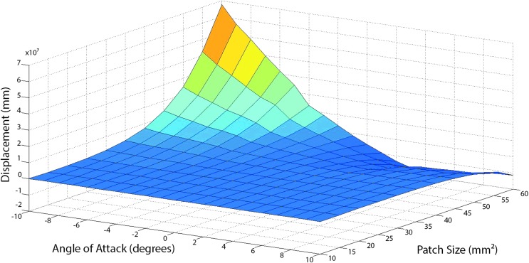
Figure 10 shows the flow chart representing the combination of VLM and using Xfoil, where VLM coupled with the Galerkin Finite Element Method (GFEM)36 result in a lift coefficient that is passed to Xfoil.35 Xfoil generates a pressure profile for each span-wise lift coefficient generated by VLM. To determine the necessary size of the skin patch, the maximum pressure is assumed at the center of the patch. The pressures generated by Xfoil within the specified patch size are summed for each pressure profile generated from independent lift coefficients within the specified patch size. Figure 11 shows the average patch pressure with respect to angle of attack and patch size. Figure 12 shows the maximum displacement of a patch plotted against the patch size and angle of attack, normalized for material and geometric constants. We find patch displacement by using the Navier solution to the Kirchhoff–Love plate theory assuming the average pressure from Figure 11 is constant across the patch. We assume the wing to be a plate and get Equation 2,
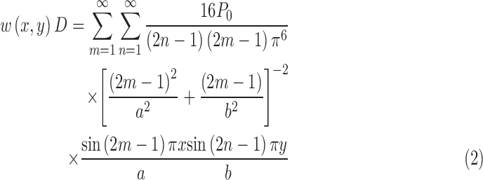 |
FIG. 10.
Aero patch sizing method. The initial geometry is given to the VLM, which generates the aerodynamic forces that are then passed to the GFEM for static analysis. If the geometry that results from the GFEM converges, a cubic spline is used to create a lift coefficient for every millimeter. Those lift coefficients are then passed to Xfoil, which generates the pressure distribution around the airfoil for each section. GFEM, Galerkin Finite Element Method; VLM, vortex lattice method.
FIG. 11.
Wing skin patch size optimization results. The average patch pressure plotted against the angle of attack and patch size.
FIG. 12.
Wing skin patch size optimization results. Maximum displacement of an assumed thin plate with the average pressure applied from Figure 11.
where:
 |
and where h is the depth of the plate, E is the modulus of elasticity, and v is Poisson's ratio. We want the largest possible patch size before the normalized displacement values become dependent on the angle of attack. Figure 12 shows this to be around 30 mm2. To fit a single cell of regular octahedra in the spar area, the resulting lattice pitch is P = 36.2 mm (1.43"), with constant chord-wise pitch.
Experimental platform
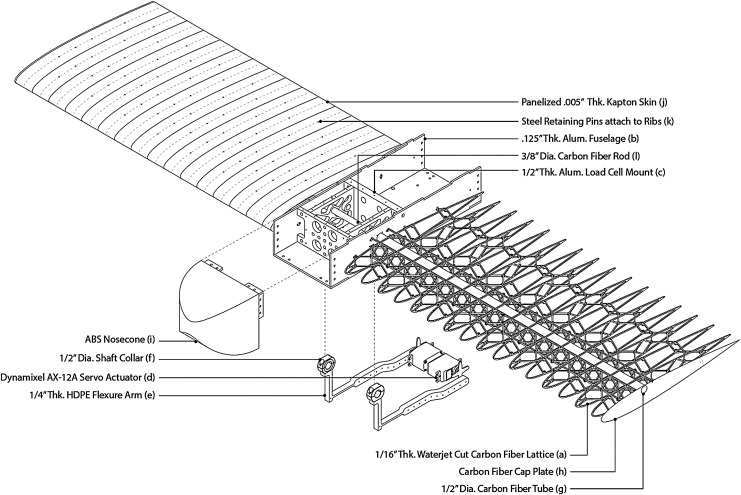
The resulting wing experiment platform (Figs. 13, 14) consists of two half wing spans (a), each attached to a central housing fuselage (b), which contains instrumentation mounting (c) and the actuation system. Beginning at the rear, a servomotor (d) is mounted to the bottom of the fuselage. A flexure delrin arm (e) is attached to the servo, which, in turn, is bolted to a shaft collar (f) that grips a carbon fiber tube (g). This tube exits the fuselage and passes through the wing's spar area. It terminates into a carbon fiber cap plate (h), which is bolted to another shaft collar gripping the tube. This allows rotation from the servo to twist the wing tip. The fuselage has a 3D printed nosecone (i), and the lattice wings are skinned with polyimide strips (j), which are attached to the structure via steel retaining pins (k). A central carbon rod minimizes cantilever deflection of the wing spans (l).
FIG. 13.
Digital Morphing Wing Platform: main components, including structure, actuation, and instrumentation.
FIG. 14.
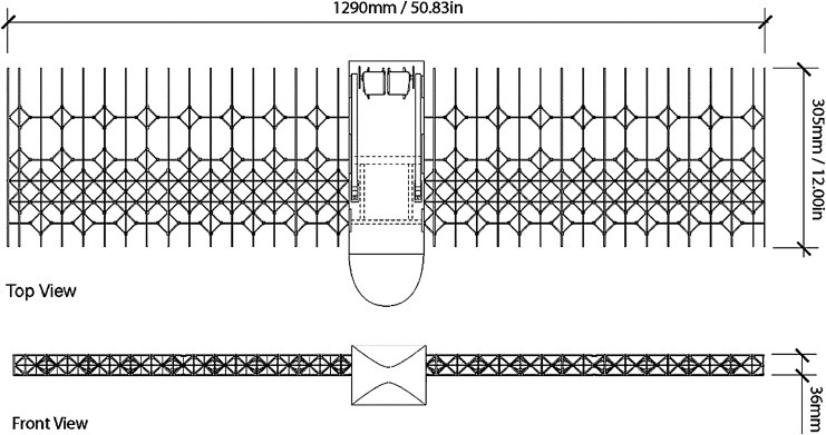
Overall wing platform dimension.
The primary wing lattice structure is decomposed into tessellated parts that are oriented similarly to conventional ribs, spars, and stringers (Fig. 15). Two rib type parts follow the NACA profile. The stringer-type parts are uniformly spaced and split across the horizontal plane to facilitate assembly from top and bottom. The spar-type part consists of a continuous perforated sheet and three types of individual parts that have uniform width and varying height, based on their location in the profile (Fig. 15).
FIG. 15.
Building-block lattice part types. (Left) Part types with main dimensions in mm; (Right) Part groups and quantities shown for half wing.
Manufacturing
To facilitate rapid assembly, the final skin design uses strips rather than patches. The skin is made from 0.127 mm-thick Kapton (polyimide film), cut into strips with hole patterns on a CO2 laser cutter. The skin requires continuity and resistance to deformation to transfer the aero loads to the frame. However, due to the morphing strategy, the skin must change shape along with the wing, while avoiding wrinkling, separation from the frame, or other changes that may negatively affect the wing performance. The skin paneling used here maintains a surface with gaps or steps smaller than 0.25 mm for actuation or morphing that produces aerodynamic control forces that are equivalent to conventional ailerons and flaps. Further details are given in the Wing Experiment Platform Details section in the Supplementary Data.
We discretize the surface into strips, parallel with the ribs, set halfway out of phase, so the center of each strip lands on a rib. To maintain a continuous surface height, the strips are layered, with one set of strips below the other. They are attached to the ribs with 0.7 mm diameter steel retaining pins, which have two legs that pass through hole patterns in the strips to grip specific locations on the rib below. The tail of the rib converges into a point with a retaining detent that mates to holes in the strip, so the small free end of the strip is then caught under a hook feature.
The fuselage anchors the two wings with an internal mounting structure. The external housing is made of 3.175 mm-thick 6061 Aluminum, lasercut with CO2 laser, and assembled via mechanical fasteners. The internal structure and instrumentation interface are 6.35 mm-thick 6061 Aluminum, three-axis milled, and assembled via mechanical fasteners. The nosecone is fabricated from ABS plastic by using standard fused deposition modeling. Further details are given in the Wing Experiment Platform Details section in the Supplementary Data.
The material used for the lattice is a custom-made quasi isotropic layup with properties shown in Table 1. Parts are cut with an abrasive water jet machine. Further details are given in the Wing Experiment Platform Details section in the Supplementary Data, Supplementary Figures S6–S9.
Table 1.
Constituent CFRP Properties
| Parameter | Value |
|---|---|
| Layup orientation | 0, 45, 90, 45, 0, −45, −90, −45, 0° |
| Sheet thickness | 0.600" ± 0.005" |
| Density (ρ) | 1600 kg/m3 |
| Young's modulus (E) | 25–28 GPa |
CFRP, carbon fiber-reinforced polymers.
Assembly
The primary part connection mechanisms are an integral snap-fit connection and a slot-type connection with a tensioned plastic cable tie (Fig. 16). The assembly sequence is as follows: (1) Snap fit and zip tie rib on stringer, (2) fill in rib with appropriate stringer cells, (3) repeat until all ribs are in place, (4) zip tie top and bottom spar, (5) zip tie to fuselage, and (6) clip on skin panels. Assembly time is 8 h.
FIG. 16.
Manual assembly technique of discrete building-block parts. (Left) Snap-fit features allow reversible joints and disassembly while still providing sufficient attachment to allow load transfer. (Right) Slot-type connections allow vertical assembly of intersecting planes and part types.
Actuation
Tip twist actuation is achieved via a flexure arm. The geometry of the arm in relation to the actuation source (servo motor) and the end effector (torque tube) achieves a favorable torque ratio, as shown in Figure 17. With a maximum torque of 29 kg/cm at 6.0 V, this results in 150 kg/cm possible torque applied to the wing tip. Driving the wing twist directly with zero mechanical advantage would require a servo with 8 × more mass and 3 × more volume. We achieve open loop control through a Pololu Mini Maestro 12, a servo control board with a native USB and a built-in scripting interface. It is mounted to the underside of the fuselage, between the two arms.
FIG. 17.
Wing mechanism actuation: (Left) Wind tunnel twist of ±10°. (Right) Wing mechanism design and mechanical advantage.
Results
Bench testing and model calibration
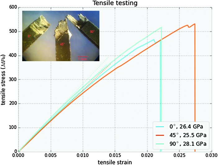
We conducted simulations of the cellular wing structure by using the modeling methods described in the Finite Element Modeling section. The goals of this effort were to validate the simulation model by using static bench testing results, and to use modal analysis to characterize the lowest natural frequencies of the structure. To calibrate material properties, we first performed coupon testing on the CFRP struts identical to the parts for the wing. Coupon tests produced an estimate of the effective elastic modulus of 25–28 GPa for the composite samples (Fig. 18). With this measured modulus, we implemented two load cases (bending and torsion) to compare modeling predictions with experimental measurements. For both tests, we assume square cross-sections, rigid load transfer between parts, and a small radius of rigidity of 0.5 mm around each node.
FIG. 18.
CFRP coupon testing results. As expected, all three orientations showed similar stiffness (with a variation of 2.6 GPa, or 9%), and the 45° sample had a slightly higher breaking strength. CFRP, carbon fiber-reinforced polymers.
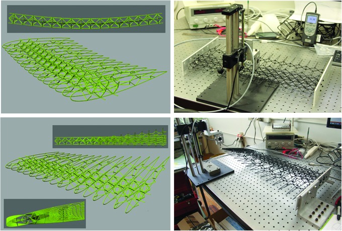
To assess bending behavior, we performed a three-point bend test. The nodes on both ends of the wing are constrained vertically (with additional displacement constraints applied along the bottom edges to limit rigid body modes), and a vertical load is applied to nodes along the central cell boundary nodes. The deflection d for a force F gives the flexural modulus as  , where L is the length spanned between edges, w is the chord-wise width of the wing, and h is the height of the wing. Because this modulus is just a comparison measure between the simulation and testing, we use the formula for a rectangular cross-section. Figure 19 shows an exaggerated representation of the deformed configuration under this loading. These simulations predict a flexural modulus of 184 MPa, close to the experimental figure of 191 MPa.
FIG. 19.
Bench testing of wing structure. (Left) Visualization of simulated bending (top) and torsion (bottom) load cases. (Right) Bench testing of load application and deflection measurement for bending and torsion load cases.
To assess twisting behavior, we performed a torsional loading test. The nodes at one end of the wing are constrained, and a vertical force is applied to the other end at the trailing edge. A deflection d for a force F gives the torsional spring constant (in Nm/radian) as  , where b is the distance from the trailing edge to the axis of rotation (assumed for the calculation to lie coincident with the torque tube), and
  = arctan(d/b) is the instantaneous rotation produced by the load. Figure 19 shows the exaggerated deformation under the torsional loading. These simulations predict a torsional spring constant of 14.9 Nm/radian in the linear range. This is again very comparable to the experimental figure of 12 Nm/radian.
The axial stiffness of the system is designed to be very high (the axial stiffness of the lattice, torque tube, and total wing are 0.3 × 10⁷, 1.2 × 10⁷, and 1.5 × 10⁷ N/m, respectively), and the expected contributions to axial load from aerodynamic and actuation forces are very low for our span-wise twist morphing application case.
Finite element simulation studies
With these calibration tests as a baseline, we characterized the dynamic behavior of the wing prototype, as well as the partial derivatives of the specific bending and torsional stiffness of the lattice with respect to design parameters.
We looked at the fundamental modes of the structures to assess its suitability for the intended actuation and twist deformation. For the dynamics of the prototype lattice, we assigned each beam a density of 1600 kg/m3, and we used Frame3dd to compute the lowest frequency modes of the structure (Fig. 20). The modal frequency values depend on how the lattice is covered and actuated, but these results provide feedback on the passive behavior of the lattice, shown in Table 2. The first fundamental mode is a pure torsional mode around the torque tube axis, whereas the second is a mix of bending and torsion of the torque tube box. The next two lowest modes are a fore-aft bending and a second-order torsional mode. This modal analysis suggests, as desired, that the wing is more compliant to torsion about the axis of the torque tube than any other elastic mechanism, making it amenable to actuation by the torque tubes. Further, these bending modes will be largely damped by the addition of the torque tube, so the lowest mode to consider in stability analysis of the full wing is the second-order torsional mode.
FIG. 20.
Visualization of modal analysis results. (L to R) First torsion mode; Coupled bending-torsion mode; Pure bending mode; Second torsion mode. Light blue is initial geometry and dark blue is the mode shape vector. Results shown are produced using the Frame3DD library.
Table 2.
Dynamic Modes of Lattice Structure
| Mode no. | Frequency (Hz) |
|---|---|
| 1st Torsion | 1.67 |
| 1st Bending-torsion | 3.76 |
| 1st In-plane bending | 4.63 |
| 2nd Torsion | 6.29 |
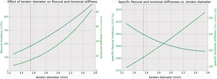
Besides using the finite element model to evaluate the elastic behavior of the wing prototype as built, we analyzed trade-offs in the design parameters. We implemented a parameter sweep for both of the calibration tests while varying the cross-sectional diameter of the lattice tendons. In Figure 21, we show the effect of varying tendon thickness on the bending stiffness and torsional stiffness of the wing. The vertical dotted line shows the wing as built. The left graph shows absolute values for the stiffness, whereas the right graph shows specific stiffness, found by dividing by the calculated tendon mass at 1600 kg/m3. For the wing as built, this calculation comes very close to the measured mass (110 and 102 g, respectively).
FIG. 21.
Simulation results of tendon diameter variation effects on flexural and torsional stiffness. (Left) Flexural stiffness and torsional stiffness over a varying cross-sectional diameter of the lattice tendons. (Right) Specific stiffnesses and specific torsional stiffness with the same variation.
Although increasing tendon thickness clearly increases both bending and torsional stiffness, we see that the specific bending stiffness remains nearly constant (falling slightly). Further, specific torsional stiffness increases greatly as we increase tendon thickness, which is not desirable for a twist-actuated wing. All this indicates that tendon diameter has an upper bound given by the supplied actuator torque, and a lower bound given by the required bending stiffness for stable flight.
Aerodynamic performance
The final means of performance quantification for the designed structure was to evaluate its performance in an actual aerodynamic environment. We conducted wind tunnel tests for a rigid wing model with a traditional flap control surface and for a flexible lattice wing model with a torque tube-actuated twist. Figure 22 shows the two models mounted in the NASA Langley 12-Foot Low-Speed Tunnel facility. Testing parameters are shown in Figure 23.
FIG. 22.
Wind tunnel testing setup in NASA Langley 12-Foot Tunnel. (Left) Rigid wing model. (Right) Flexible wing model.
FIG. 23.
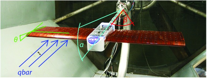
Wind tunnel test parameters. Dynamic pressure (qbar), wing tip twist (θ), angle of attack (α), and sideslip angle (β).
The rigid model was tested at various dynamic pressures, from 2 to 4 psf, with a sweep of the angle of attack from −4° to 24° and asymmetric flaperons at 10°, 20°, and 30°. The flexible wing model was tested over the same range of dynamic pressures but over a range of angle of attack from −4° to 16° with an asymmetric wing twist of 2°, 4°, and 6°.
Overall, the active twist wing replicated the performance envelope of the rigid model. In addition, several properties of the morphing wing emerged that we did not see with the rigid model. The flexible model showed the capability to change from adverse to proverse yaw in a linear fashion with the angle of attack. The active twist model also showed stall mitigation via twist during wind tunnel testing. We see that a 4° tip twist configuration ends up having the highest lift-to-drag ratio for the flexible model, whereas the 0° flaperon gives the highest lift-to-drag ratio for the rigid model. This suggests that the wing tip twist is a more effective means of increasing lift, (Supplementary Figures S10–S11). Full static results from the test are presented in Cramer et al.37
There are benefits that are attributable to the fact that the soft robotic wing structure exhibits continuum control surface deformation that wings with rigid control surfaces cannot achieve. There is evidence that the form drag is reduced for the flexible model at low angle of attacks when compared with the rigid model. This is because at low angles of attack the flaperon results in a larger cross-sectional area that is exposed to the flow direction. The low angles of attack are used for the operational cruise conditions, meaning that the drag reduction gains in this region have a disproportionate effect on the overall performance of an aircraft.
There is a broad range of scale and experimental setup for morphing aircraft, ranging from full aircraft size experiments,38 to small-scale flying UAV's,39 to full-scale military aircraft.40,41 As a result, it is often difficult to find directly comparable morphing wing technologies. Also, many of these morphing aircrafts use some smart material or nontraditional means of actuation.42 The most comparable work was done by Majji et al.43 and Vos et al.44 Both of them used a servo-driven torque rod system and performed wind tunnel testing though both used half-span wall-mounted wings. Both were able to show the ability to tailor the lift coefficient at various angles of attack, whereas Vos et al. also investigated drag and lift/drag ratios. Vos et al. showed similar lift drag efficiency gains by twisting down at stall and up at low angle of attacks that we found.
Discussion
We have demonstrated the design, analysis, fabrication, and performance of an elastic continuum robotic structure with heterogeneous properties, in the form of a span-wise twisting wing. This work was presented as a generalizable approach for the design, analysis, and fabrication of a robot requiring tunable, lightweight, and actively deformable elastic structures, utilizing reversibly assembled cellular composite materials.
We described an approach for using modular elements to construct cellular composite structures. These discrete lattice parts can be used to create meta-materials with properties determined by their base material and lattice geometry. It is possible to attain continuum robotic behavior across a range of moduli with the same set of parts by varying their geometry, at densities that are not attainable by using conventional soft materials. This can be used to build lightweight, integrative, and deformable structures. This approach is promising for robotic applications beyond the morphing wing case study presented.
We developed a morphing wing structure as an instantiation of the digital cellular composite system, whose design includes wing structure, skin, fuselage, and actuation system, including motors, controls, and mechanisms. The manufacturing process of the modular elements enables mass production by using high-performance composites. The digital cellular composite elements are assembled by hand with reversible mechanical connections.
We leveraged the discrete and repetitive nature of the lattice to simplify analysis models, and we used the physical testing of parts to hierarchically predict larger assembly behavior. Quasi-static bench testing of a built structure demonstrated the accuracy of this method. We used this approach to predict the fundamental modes of the structure.
We then tested the wing prototype in the NASA Langley 12-Foot Low-Speed Tunnel facility together with a rigid wing model with control surfaces (flaps) to assess the performance of the morphing wing. The morphing wing could use active twist to replicate the performance of the rigid wing model. Through active wing twist, it is possible to have several benefits, including stall mitigation.
In the morphing wing case study, the manufacturing technique is driven by the object's scale (<1 m). However, this particular technique may not scale up or down favorably due to the resolution of abrasive waterjet cutting. Smaller parts can be manufactured by laser cutting, or by injection molding, utilizing aligned fiber reinforcement for improved mechanical properties. Larger parts can be assembled manually or robotically. Pultruded carbon fiber struts can be assembled with injection molded nodes to achieve large-scale lattice structures.17 This technique can be used for structures with lattice pitch ranges of 10−1 to 102 m, and it may be a good candidate process for automation.
The ability for digital cellular structures to achieve large strain, comparable to elastomeric structures, depends on their base material. Due to the discrete assembly of these structures, it is possible to incorporate heterogeneous materials into a single assembled structure. This way, higher strain materials can be placed in areas where elongation is needed, whereas stiffer materials can reside in areas where deflection should be minimized. Postbuckling, nonlinear behavior of these lattices is also an active research topic.
Lessons from these experiments will be applied to complete aircraft with full flight controls using active elastic deformation.
Supplementary Material
Acknowledgments
The authors would like to acknowledge the efforts of the Langley Research Center Flight Dynamics Branch and the 12-Foot Wind Tunnel test team: Mike Fremeaux, Mark Croom, Mia Siochi, Wes Oneal, Clinton Duncan, Lee Pollard, Earl Harris, Sue Grafton, and Gary Wainwright, as well as the MIT AeroAstro Department, including Dick Perdichizzi with the MIT Wright Brothers Wind Tunnel. Funding for this work was provided by the NASA Aeronautics Research Institute Team Seedling Program (Active Wing Shaping Control Concept Using Composite Lattice-based Cellular Materials), including NASA grant NNX14AG47A, as well as the NASA ARMD Convergent Aeronautics Solutions Program (Mission Adaptive Digital Composite Aerostructures Technologies), and the NASA Space Technology Research Fellowship (NSTRF) Program.
Author Disclosure Statement
No competing financial interests exist.
References
- 1.Manti M, Hassan T, Passetti G, D'Elia N, Laschi C, Cianchetti M. A bioinspired soft robotic gripper for adaptable and effective grasping. Soft Robot 2015;2:107–116 [Google Scholar]
- 2.Zhang Y, Kim WS. Highly sensitive flexible printed accelerometer system for monitoring vital signs. Soft Robot 2014;1:132–135 [Google Scholar]
- 3.Marchese AD, Onal CD, Rus D. Autonomous soft robotic fish capable of escape maneuvers using fluidic elastomer actuators. Soft Robot 2014;1:75–87 [DOI] [PMC free article] [PubMed] [Google Scholar]
- 4.Gerdes J, Holness A, Perez-Rosado A, Roberts L, Greisinger A, Barnett E, et al. Robo Raven: a flapping-wing air vehicle with highly compliant and independently controlled wings. Soft Robot 2014;1:275–288 [Google Scholar]
- 5.Trivedi D, Rahn CD, Kier WM, Walker ID. Soft robotics: Biological inspiration, state of the art, and future research. Appl Bionics Biomech 2008;5:99–117 [Google Scholar]
- 6.Rus D, Tolley MT. Design, fabrication and control of soft robots. Nature 2015;521:467–475 [DOI] [PubMed] [Google Scholar]
- 7.Robinson G, Davies JBC. Continuum robots-a state of the art. Robot Autom 1999;4:2849–2854 [Google Scholar]
- 8.Gibson L. Cellular Solids: Structure and Properties. New York: Cambridge University Press, 1999 [Google Scholar]
- 9.Ashby MF. The properties of foams and lattices. Philos Trans A Math Phys Eng Sci 2006;364:15–30 [DOI] [PubMed] [Google Scholar]
- 10.Deshpande VS, Ashby MF, Fleck NA. Foam topology: bending versus stretching dominated architectures. Acta Mater 2001;49:1035–1040 [Google Scholar]
- 11.Bathe KJ. The Mechanics of Solids and Stuctures—Hierarchical Modeling and the Finite Element Solution. Berlin, London: Springer, 2011 [Google Scholar]
- 12.Wu X, Downes M. Adaptive nonlinear finite elements for deformable body simulation using dynamic progressive meshes. Comput Graph 2001;20:349–358 [Google Scholar]
- 13.Onal CD, Rus D. A modular approach to soft robots. Proceedings of IEEE RAS & EMBS International Conference on Biomedical Robotics and Biomechatronics 2012;1038–1045 [Google Scholar]
- 14.Germann J, Maesani A, Pericet-Camara R, Floreano D. Soft cells for programmable self-assembly of robotic modules. Soft Robot 2014;1:239–245 [Google Scholar]
- 15.Hiller J, Lipson H. Dynamic simulation of soft multimaterial 3D-printed objects. Soft Robot 2014;1:88–101 [Google Scholar]
- 16.Jenett B, Cellucci D, Gregg C, Cheung KC. Meso-scale digital materials: modular, reconfigurable, lattice-based structures, in Proceedings of the 2016 Manufacturing Science and Engineering Conference, 2016 [Google Scholar]
- 17.Cho K-J, Koh J-S, Kim S, Chu WS, Hong Y, Ahn SH. Review of manufacturing processes for soft biomimetic robots. Int J Precis Eng Manuf 2009;10171–181 [Google Scholar]
- 18.Marchese AD, Katzschmann RK, Rus D. A recipe for soft fluidic elastomer robots. Soft Robot 2015;2:7–25 [DOI] [PMC free article] [PubMed] [Google Scholar]
- 19.Qi R, Lam TL, Xu Y. Mechanical design and implementation of a soft inflatable robot arm for safe human-robot interaction, in Proceedings of the IEEE International Conference on Robotics and Automation 2014;3490–3495 [Google Scholar]
- 20.“otherlab.” www.pneubotics.com/ (last accessed January6, 2015)
- 21.Sanan S, Lynn PS, Griffith ST. Pneumatic torsional actuators for inflatable robots. J Mech Robot 2014;6:031003 [Google Scholar]
- 22.Grunbaum B. Uniform Tilings of 3-space. Geocombinatorics 1994;4:49–56 [Google Scholar]
- 23.Cheung KC, Gershenfeld N. Reversibly assembled cellular composite materials. Science 2013;341:1219–1221 [DOI] [PubMed] [Google Scholar]
- 24.Zheng X, Lee H, Weisgraber TH, Shusteff M, DeOtte J, Duoss EB, et al. Ultralight, ultrastiff mechanical metamaterials. Science 2014;344:1373–1377 [DOI] [PubMed] [Google Scholar]
- 25.Meza LR, Das S, Greer JR. Strong, lightweight and recoverable three-dimensional ceramic nanolattices. 2014;345:1322–1326 [DOI] [PubMed]
- 26.Cheung KC. Digital Cellular Solids: Reconfigurable Composite Materials. Massachusetts Institute of Technology, Cambridge, MA: 2012 [Google Scholar]
- 27.Andrews E, Gioux G, Onck P, Gibson L. Size effects in ductile cellular solids. Part II: experimental results. Int J Mech Sci 2001;43:701–713 [Google Scholar]
- 28.Calisch S. Physical Finite Elements. Massachusetts Institute of Technology, Cambridge, MA: 2014 [Google Scholar]
- 29.Gavin HP. Frame3dd: static and dynamic structural analysis of 2d and 3d frames. http://frame3dd.sourceforge.net/ (accessed July6, 2014), GPL License
- 30.Stanewsky E. Aerodynamic benefits of adaptive wing technology. Aerosp Sci Technol 2000;4:7439–452 [Google Scholar]
- 31.Barker A. Composite Materials for Aircraft Structures. AIAA, Reston, VA: 2004 [Google Scholar]
- 32.Stanewsky E. Adaptive wing and flow control technology. Prog Aerosp Sci 2001;37:583–667 [Google Scholar]
- 33.NACA 0012 Airfoil Profile. http://turbmodels.larc.nasa.gov/naca0012_val.html (accessed January1, 2013)
- 34.Melin T. A Vortex Lattice MATLAB Implementation for Linear Aerodynamic Wing Applications. Stockholm, Sweden: Royal Institute of Technology (KTH), 2000 [Google Scholar]
- 35.Drela M. XFOIL: An analysis and design system for low Reynolds number airfoils. In: Conference on Low Reynolds Number Airfoil Aerodynamics; Vol. 54, pp 1–12, 1989 [Google Scholar]
- 36.Strouboulis T, Copps K, Babuška I. The generalized finite element method. Comput Methods Appl Mech Eng 2001;190:4081–4193 [Google Scholar]
- 37.Cramer N, Cheung K, and Swei S. "Design and Testing of a Lattice-based Cellular Component Active Twist Wing", 24th AIAA/AHS Adaptive Structures Conference, AIAA SciTech; AIAA 2016;1085 [Google Scholar]
- 38.Miller G. Active flexible wing (AFW) technology. No. NA-87-1515L. Los Angeles, CA: Rockwell International North American Aircraft Operations, 1988 [Google Scholar]
- 39.Abdulrahim M, Garcia H, Ivey GF, Lind R. Flight testing: a micro air vehicle using morphing for aeroservoelastic control. J Aircr 2005;42:1–17 [Google Scholar]
- 40.Pendleton EW, Bessette D, Field PB, Miller GD, Griffin KE. Active aeroelastic wing flight research program: technical program and model analytical development. J Aircr 2000;37:554–561 [Google Scholar]
- 41.Kudva J, Martin C, Scherer L, Jardine A, McGowan A, Lake R, et al. Overview of the DARPA/AFRL/NASA smart wing program. In: SPIE Conference on Industrial and Commercial Applications of Smart Structure Technologies;Vol.3674, pp. 3–9, 1999 [Google Scholar]
- 42.Barbarino S, Bilgen O, Ajaj RM, Friswell MI, Inman DJ. A review of morphing aircraft. J Intell Mater Syst Struct 2011;22:823–877 [Google Scholar]
- 43.Majji M, Rediniotis O, Junkins J. Design of a morphing wing: modeling and experiments. In AIAA Atmospheric Flight Mechanics Conference and Exhibit, p. 9, 2007 [Google Scholar]
- 44.Vos R, Gurdal Z, Abdalla M. Mechanism for warp-controlled twist of a morphing wing. J Aircr 2010;47:450–457 [Google Scholar]
Associated Data
This section collects any data citations, data availability statements, or supplementary materials included in this article.


