Significance
Neurons in the brain extend long dendrites that are packed with small protrusions, or spines, responsible for receiving information from presynaptic axons. Although we know much about the workings of spines, we know little about the large-scale distribution of the properties of these compartments along dendritic trees. Here, we provide a map of the structure and function of spines along dendrites. We find that synapses are not randomly distributed, but show a gradual decrease in size with distance along a dendrite, which is matched by an increase in the amplitude of neurotransmitter-evoked calcium signals. This distance-dependent gradient in calcium signals will have important implications for neuronal integration of synaptic information and for the rules behind the calcium-driven plasticity of spines.
Keywords: dendritic spine, calcium, NMDA, dendrite, hippocampus
Abstract
Neurons receive a multitude of synaptic inputs along their dendritic arbor, but how this highly heterogeneous population of synaptic compartments is spatially organized remains unclear. By measuring N-methyl-d-aspartic acid receptor (NMDAR)-driven calcium responses in single spines, we provide a spatial map of synaptic calcium signals along dendritic arbors of hippocampal neurons and relate this to measures of synapse structure. We find that quantal NMDAR calcium signals increase in amplitude as they approach a thinning dendritic tip end. Based on a compartmental model of spine calcium dynamics, we propose that this biased distribution in calcium signals is governed by a gradual, distance-dependent decline in spine size, which we visualized using serial block-face scanning electron microscopy. Our data describe a cell-autonomous feature of principal neurons, where tapering dendrites show an inverse distribution of spine size and NMDAR-driven calcium signals along dendritic trees, with important implications for synaptic plasticity rules and spine function.
Principal neurons in the hippocampus have large dendrites that receive tens of thousands of excitatory inputs, mainly on dendritic spines (1). However, it is still unclear how these highly heterogeneous inputs are distributed, both structurally and functionally, along a dendritic arbor. Dendritic spines are specialized postsynaptic structures that cluster glutamate receptors and act as compartments that physically restrict the diffusion of key signaling molecules and therefore confine the induction and expression of plasticity to individual synapses (2). Specifically, the activation of NMDA receptors (NMDARs) results in increases in calcium restricted to individual spines that initiate long-term forms of activity-dependent plasticity (3, 4). In fact, the levels and spatial spread of calcium during synaptic activity are thought to determine the direction and specificity of synaptic plasticity (3, 5, 6). As a result, rises in calcium within a spine head provide an important and unique readout of synapse function. Very little is known about the calcium signals elicited by NMDARs along dendritic trees and whether they vary with dendritic position. This is surprising considering the important role that calcium plays in all manner of intracellular events, especially during activity-dependent forms of synaptic plasticity. Furthermore, because calcium signals are highly dependent on spine morphology, as well as the number and properties of NMDARs, a measure of spine structure and synaptically activated calcium influx will not only provide a crucial map of calcium domains along a dendrite but also shed light on the distribution of NMDARs throughout the dendritic tree.
Dendritic trees vary dramatically in shape and size across different neuron types. They also show a remarkable degree of morphological heterogeneity within a given neuron, mainly as a result of dendritic branching and tapering, with important functional consequences on dendritic integration and neuronal output. A key unanswered question is to understand how synapses are distributed along nonuniform dendritic structures and whether they account for the local inhomogeneities of dendrites. Here, we describe the structure and function of populations of spines in hippocampal pyramidal neurons from cultured preparations through to organotypic slices and the intact brain. We find a common theme that extends across all these preparations, where postsynaptic compartments decrease in size when moving toward the thin high impedance tips of dendrites. In parallel to this, we also find that spontaneous postsynaptic calcium events triggered by activation of NMDARs show an increase in amplitude toward dendritic tip ends, resulting in an inverse relationship between calcium concentration and spine size, suggesting a relatively uniform distribution of NMDARs along tapering dendrites. Our findings provide a map of NMDAR calcium signals along dendritic trees and suggest that dendritic location is an important determinant of synapse structure and function.
Results
Visualizing NMDAR-Driven “Minis” in Dendritic Spines.
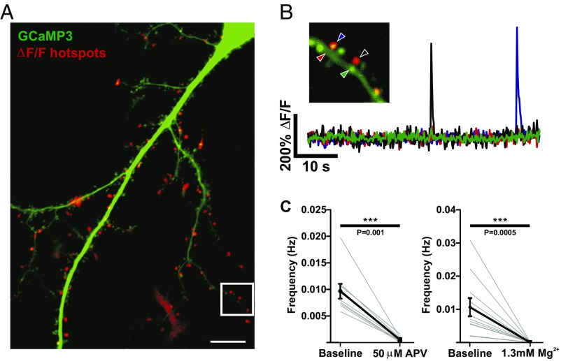
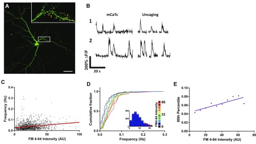
We set out to provide a description of synapse function along dendritic arbors, including distal domains, which could then be matched to measures of spine structure. The properties of excitatory synaptic inputs are often obtained from electrophysiological recordings of spontaneous excitatory postsynaptic currents [miniature excitatory postsynaptic currents (mEPSCs) or minis], providing a measure of both presynaptic and postsynaptic strength inferred from the frequency and amplitude of events, respectively. However, one major drawback of this approach is its lack of spatial information, as spontaneous events that occur stochastically along the dendritic tree are all recorded at the soma. In addition, electrophysiological recordings also suffer from possible distortions, especially when assessing distal spines along thin dendrites, including dendritic filtering that arises from the morphology of the dendrite (7). To bypass these issues, we initially measured functional responses in single spines by using genetically encoded calcium sensors (Fig. 1). Isolated dissociated hippocampal neurons were transfected with the calcium sensor GCaMP3 and imaged in the presence of tetrodotoxin (TTX) (1 μM) to block all neuronal activity and in the absence of extracellular Mg2+ to favor NMDAR activation (8, 9). Time-series imaging using either wide-field imaging of entire dendrites (Fig. 1A; Movie S1) or confocal microscopy showed robust spontaneous increases in fluorescence that were highly localized to dendritic spines (Fig. 1B) and were blocked by addition of Mg2+ or the specific NMDAR antagonist (2R)-amino-5-phosphonovaleric acid (APV) (Fig. 1C). These spontaneous calcium transients [miniature calcium transients (mCaTs)] occurred stochastically at different spines and likely represent the activation of NMDARs by glutamate released spontaneously from single presynaptic vesicles, thus allowing us to image spine function by measuring the quantal activation of single spines along a dendrite. To further confirm that we were detecting quantal postsynaptic events, we measured calcium events that either occurred spontaneously (mCaTs) or in response to local uncaging of caged glutamate, at the same spine. We found that the mean amplitudes of mCaTs were similar to those induced by an uncaging stimulus that is equivalent to the size of an mEPSC (10) (Fig. S1 A and B) and therefore indicating our system was sensitive enough to detect quantal rises in calcium. Previous studies have shown that spontaneous release is correlated with synapse size and release probability (11, 12). We therefore performed mCaT measurements on synapses previously stained with the membrane dye FM4-64 to label the recycling pool of vesicles and showed a positive correlation between mCaT frequency and presynaptic vesicle pool size (Fig. S1 C–E). Together, our data show that mCaTs originate from the spontaneous release of neurotransmitter presynaptically.
Fig. 1.
Dendritic spine calcium transients are NMDAR dependent. (A) A dissociated hippocampal neuron expressing GCaMP3 (green) overlaid with a ΔF/F summary image of calcium transient hot spots in red. White box indicates area in B. (Scale bar, 10 μm.) (B) A dendritic section. ΔF/F traces from ROIs of either spine or dendritic regions indicated by arrowheads. Each trace is color-matched to an arrowhead. (C) mCaT frequency in control bath solution and in the presence of 50 µM APV, or 1.3 mM Mg2+. Faint gray lines show the mean frequency for each cell, and black lines show the mean and SEM for all cells. APV, n = 10 cells, number of spines = 549; Mg2+, n = 11 cells, number of spines = 571; Wilcoxon signed-rank test; APV, P = 0.001; Mg2+, P = 0.0005.
Fig. S1.
Evidence for spontaneous release driving postsynaptic mCaTs. (A) A typical neuron expressing GCaMP3. White box indicates the area imaged to record spontaneous and uncaging-evoked activity shown in Inset. (Scale bar, 20 μm.) (Inset) Yellow circles indicate ROIs and correspond to fluorescence traces in B. (B) Left shows representative mCaTs recorded under spontaneous conditions for spines 1 and 2. Right shows representative calcium transients recorded following MNI-glutamate uncaging (0.2-ms light pulses) on three sequential trials at the same spine. (C) Correlation of mCaT frequency with FM4-64 staining. mCaT frequency plotted as a function of FM4-64 intensity, n = 1,689 spines. Spearman’s coefficient, P < 0.0001. (D) Cumulative frequency distributions for mCaT frequency for each spine, where each plot is color matched to a different bin for FM4-64 intensity shown in the key to the Right. Inset histograms show the number of spines included within each FM4-64 intensity bin. (E) The 80th percentile values for frequency obtained from the cumulative frequency graphs, plotted as a function of FM4-64 intensity. Spearman’s coefficient: P = 0.006.
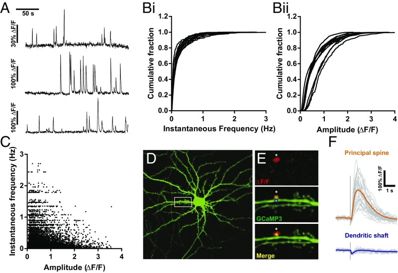
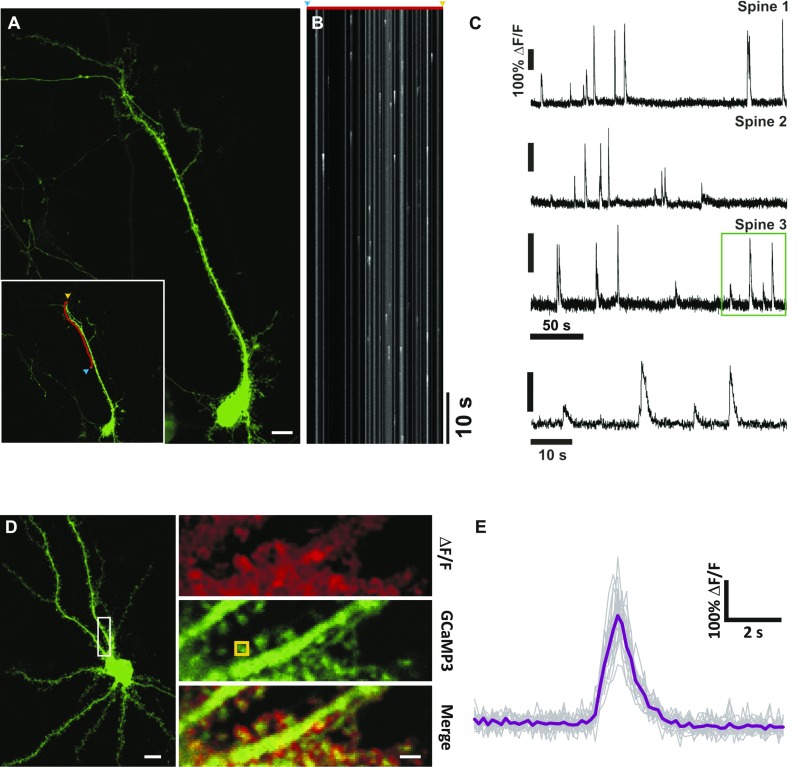
One surprising feature of mCaTs was the high levels of heterogeneity in both amplitude and frequency across spines (Fig. 2 A and B). In fact, we found that spontaneous events were biased toward a few spines that showed higher frequencies, so that 50% of all events imaged along a neuron occurred in only about 15% of all spines measured. We also found that there was a negative correlation between amplitude and instantaneous frequency across spines, such that higher frequency spines showed smaller events (Fig. 2C). The amplitude of events was not only variable across spines but also within single spines (Fig. 2A), with an average coefficient of variation (CV) per spine of 67% (restricted to spines with no fewer than 10 events). This was not due to limitations in temporal sampling as line-scan imaging also showed a high degree of variability (51%; Fig. S2 A–C). To establish the origin of this variability, we performed local uncaging experiments that would bypass the presynaptic terminal and therefore remove one potential source of variability (Fig. 2 D–F). Single uncaging pulses were elicited at single spines to induce a postsynaptic response that was similar to a quantal response. A single uncaging pulse delivered at the same spine multiple times with a long interval (15 s) showed that calcium events remained highly variable (Fig. 2F) with a CV similar to that observed for spontaneous events (CV = 50%). To control for other sources of variability in the system, we also measured calcium events in spines in response to backpropagating action potentials elicited by extracellular stimulation (Fig. S2 D and E) and found a much lower degree of variability (CV = 23%), suggesting that the variability was primarily due to activation of synaptic NMDARs. Our findings show that the great majority of the variability in spine calcium events was postsynaptic in origin with only a limited presynaptic contribution.
Fig. 2.
mCaTs are highly heterogeneous across the dendritic tree and within single spines. (A) ΔF/F traces from three different spines during the same recording. (B) Cumulative frequencies describing the distributions of instantaneous frequency (i) and amplitude (ii) of mCaTs for individual cells. (C) The amplitudes of individual mCaTs as a function of the instantaneous frequency of that event; n = 11 cells. (D) Hippocampal neuron expressing GCaMP3. White box corresponds to the area shown in the zoomed regions to the Right. (Scale bar, 10 μm.) (E) Repetitive uncaging of glutamate was performed at a single spine with UV laser (405-nm, 0.05-ms pulse) at a single point (indicated by the white asterisk). Top shows a ΔF/F summary image of an uncaging-induced calcium transient. Middle shows GCaMP3 expression within this dendritic segment, with the positions of the ROIs used. Bottom is a merge of the above panels. (F) Faint gray traces show responses at the principal spine and dendritic shaft for each uncaging trial delivered every 15 s at the principal spine and dendritic shaft as labeled (n = 33 trials). Mean responses for the principal spine and dendritic shaft are shown by bold orange and blue traces, respectively.
Fig. S2.
High mCaT variability is not due to limitations in temporal resolution or calcium measurements at the spine. (A) A typical hippocampal neuron expressing GCaMP3. (Scale bar, 10 μm.) (Inset) Red line indicates the region used to record the line scan in B, drawn to pass through multiple spine heads. The blue arrow indicates the start, and the yellow arrow, the end position. (B) An example line scan recording. The red line and arrows above indicate the spatial extent of the scan. (C) ΔF/F line scan traces for three different spines (labeled spine 1–3). Note the high variability in amplitude at each example spine. Bottom trace shows a zoomed portion of the ΔF/F trace area indicated by green box, spine 3. (D) An example neuron expressing GCaMP3. (Scale bar, 10 μm.) White box indicates zoomed area in panels. Top shows a ΔF/F summary image of action potential-induced calcium transients. Middle shows GCaMP3 expression within this dendritic segment, with the positions of the ROI used to calculate the ΔF/F traces shown in E overlaid. Bottom is a merge of the above panels. (Scale bar, 2 μm.) (E) Faint gray traces show responses for each extracellular stimulation, n = 15 trials. The mean response for this ROI is shown in purple. The average CV for all, n = 9 spines from 4 cells, had a CV of 23.6% as displayed on the figure; this example had a CV of 20.1%.
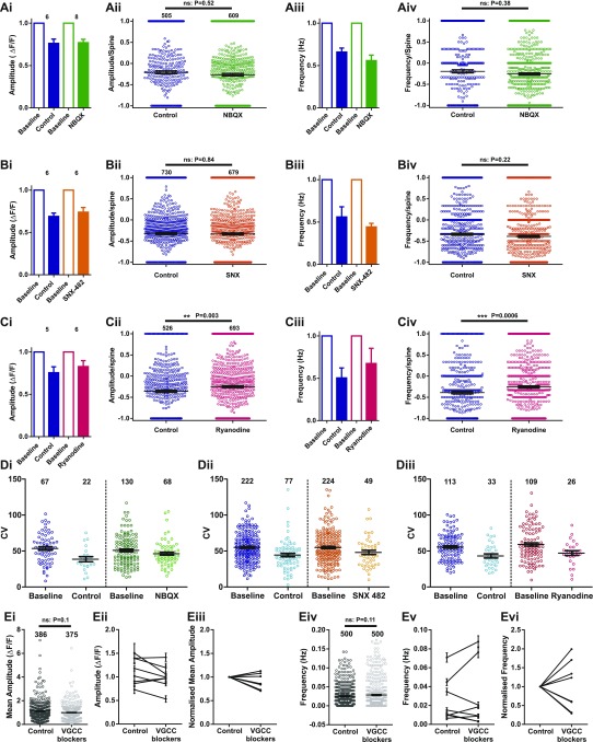
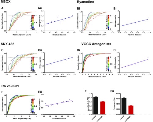
To try to pinpoint the molecular origin of this variability, we performed pharmacological experiments to silence specific channels/compartments that may contribute to the calcium signal (Fig. S3). We found that blocking α-amino-3-hydroxy-5-methyl-4-isoxazolepropionic acid (AMPA)/kainate receptors, ryanodine-sensitive intracellular stores, R-type voltage-gated calcium channels (VGCCs), or all VGCCs did not reduce the amplitude or frequency of NMDAR-driven responses described here, nor did they contribute to the heterogeneity of the mCaT response (Fig. S3). Instead, we believe that the large variability in amplitude is likely to arise from the stochastic opening of the few NMDARs activated in response to glutamate release from presynaptic terminals.
Fig. S3.
mCaT amplitude and frequency following pharmacological blockade. (A–C) Summary of mCaT amplitude and frequency following treatment with 10 μM NBQX (A) (green data), 30 μM ryanodine (B) (pink data), and 500 nM SNX-482 (C) (orange data). Average amplitude (i) or frequency (iii) per cell in baseline and control conditions (blue bars) and in baseline and under drug treatment. Summary of the difference in net amplitude (ii) and frequency (iv) at individual spines. Notations of n numbers of cells (A–Ci and iii) or spines (A–Cii and iv) are indicated above each amplitude graph and are identical for frequency. Mann–Whitney statistics were used, with P values displayed on the graphs. (Di–iii) Each point represents the coefficient of variation (CV) of an individual spine that exhibited five or more events in baseline and control or drug conditions as indicated. n numbers of spines are indicated above each condition. (i) 10 μM NBQX, (ii) 500 nM SNX-482, and (iii) 30 μM ryanodine. (E) GCaMP6f-expressing cells treated with a mixture of VGCC antagonists (1 μM nifedipine, 0.15 μM ω-Aga-TK, 3 μM ω-Cono-GVIA, 1 μM SNX, and 10 μM TTA-P2). (i) Mean mCaT amplitude per spine before and after drug treatment: before, n = 386; after, n = 375 spines from 8 cells; Mann–Whitney, P = 0.1. (ii) Mean amplitude and SEM per cell, n = 8 cells. (iii) Mean amplitude after VGCC treatment normalized to baseline mCaT amplitude, n = 8 cells. (iv) mCaT frequency per spine before and after drug treatment, n = 500 spines from 8 cells; Wilcoxon, P = 0.11. (v) Mean mCaT frequency and SEM per cell, n = 8 cells. (vi) Mean frequency after VGCC treatment normalized to baseline mCaT frequency, n = 8 cells.
Mapping mCaTs Along Dendritic Trees.
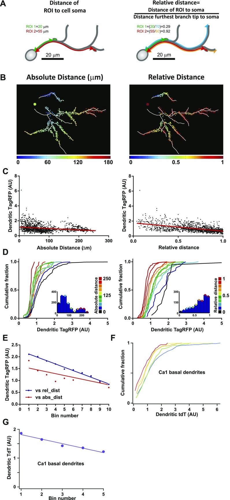
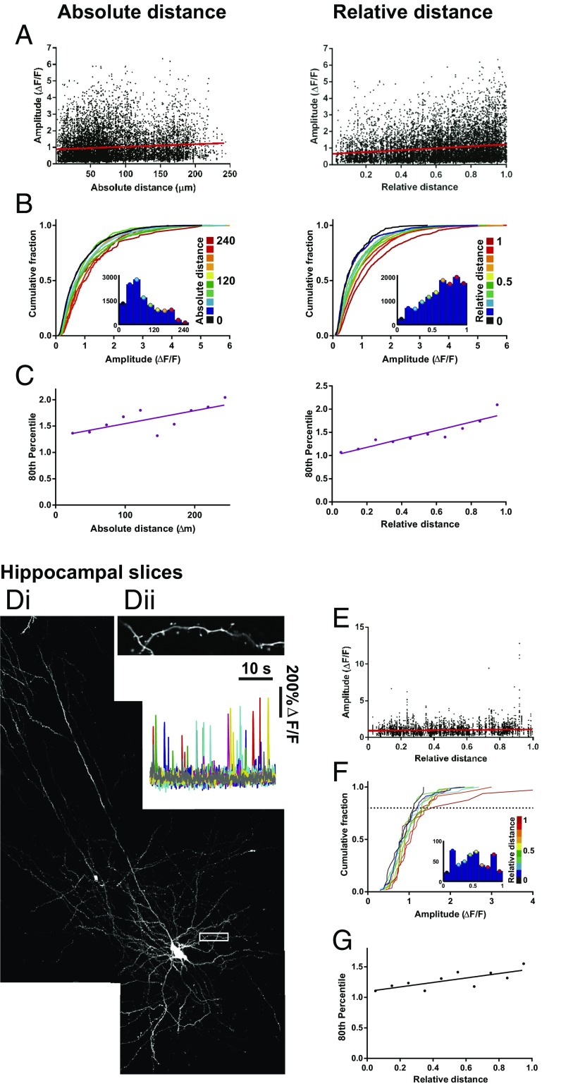
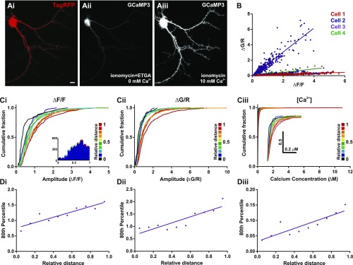
We next sought to establish whether the distribution of synaptic events was biased in any way to a particular location along the dendritic tree. For this purpose, live imaging of neurons was performed so that entire dendritic trees were purposely included within the imaging window. To map the distribution of mCaTs along an arbor, the dendritic tree was traced, and regions of interest (ROIs) were picked for each spine along the traced dendrites. Each ROI was then assigned to its corresponding dendrite to establish the position of spines along the dendritic tree (Fig. S4). Two measures were used to define dendritic location: (i) the absolute distance of each ROI to the cell body (direct path to the soma), and (ii) the relative distance, defined as the absolute distance of an ROI to the soma normalized to the distance from the soma to the furthest branch tip (Fig. S4 A and B). The measure of relative distance was taken to account for local inhomogeneities that could affect synaptic properties, such as the gradual decrease in dendrite diameter observed toward dendritic tips in dissociated neurons (Fig. S4 C–E) and neurons from the intact brain (Fig. S4 F–G). We found that both the amplitude (Fig. 3 A–C) and integral (data not shown) of calcium events (obtained from the ΔF/F responses) showed strong positive correlation with distance. Interestingly, these measures of mCaT amplitude are better correlated to relative rather than absolute distance, which may suggest that this measure is particularly sensitive to local inhomogeneities in dendritic structure, such as dendrite diameter. Similar distributions were also observed when measuring ΔG/R (Materials and Methods) in neurons coexpressing GCaMP3 and TagRFP or when normalizing the data to the maximum and minimum fluorescence values obtained from ionomycin treatment following an imaging session (Fig. S5). Interestingly, we found that the average frequency measured in single spines showed a negative correlation with absolute distance to the soma but was not significantly correlated to relative distance, even if a trend was apparent (data not shown).
Fig. S4.
Metrics for measuring dendritic position. (A) A schematic detailing two metrics used to define dendritic tree position of ROIs; distance from the soma (absolute distance) and relative distance as indicated by the calculation. (B) Tracings of an example cell with ROIs (squares) color-coded for dendritic tree position according to absolute and relative distance. Scales are located below each image. (C) TagRFP intensity of the dendritic branch at different locations, considered as a proxy measurement for dendrite diameter, plotted as a function of absolute, or relative distance, n = 1,353 locations. (D) Cumulative frequency distributions for dendritic TagRFP intensity, where each plot is color matched to a different bin for absolute or relative distance shown in the key to the Right. Inset histograms show the number of dendritic locations included within each distance bin. (E) The 80th percentile values for dendritic TagRFP intensity obtained from the cumulative frequency graphs, plotted as a function of distance bins. Spearman’s coefficient: absolute distance, P = 0.02; relative distance, P < 0.0001. (F) Cumulative frequency distribution for dendritic tdT in CA1 neurons from histological hippocampal tissue. Each plot corresponds to a bin that color-coded as above for distance along a basal dendrite. (G) The 80th percentile values for dendritic tdT intensity obtained from the cumulative frequency graphs in F, plotted as a function of distance bins. Spearman’s coefficient: P ≤ 0.0001.
Fig. 3.
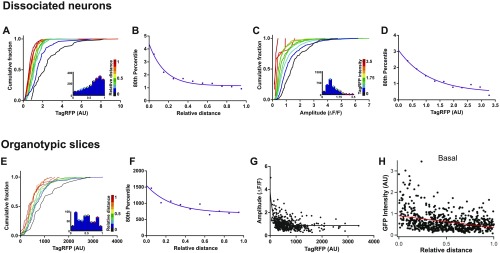
Distribution of mCaT amplitude across the dendritic trees of hippocampal neurons from dissociated and organotypic slice cultures. (A) mCaT amplitude in dissociated neurons plotted as a function of absolute or relative distance; n = 12,534 mCaTs from 11 cells. Spearman’s correlation, absolute distance, P = 0.02; relative distance, P < 0.0001. (B) Cumulative frequency distributions for mCaT amplitude, where each plot is color matched to a different bin for absolute or relative distance, as shown in the key to the Right of each plot. Inset histograms show the number of spines included within each distance bin. (C) The 80th percentile values for mCaT amplitude obtained from the cumulative frequency graphs, plotted as a function of absolute or relative distance. Spearman’s coefficient: absolute distance, P = 0.02; relative distance, P < 0.0001. (D) Example neuron from organotypic hippocampal slice coexpressing TagRFP and GCaMP3. White box corresponds to the area shown in the zoomed region in Dii. (Dii) ΔF/F traces of mCaTs from spines shown in the zoomed region. (E) Mean amplitude per spine plotted as a function of relative distance. Spearman’s correlation, P = 0.0002, n = 604. (F) Cumulative frequency distributions for mean mCaT amplitude per spine, where each plot is color matched to a different bin for relative distance, as shown in the key to the Right of each plot. Inset histograms show the number of spines included within each distance bin. (G) The 80th percentile values for mCaT amplitude obtained from the cumulative frequency graphs, plotted as a function of relative distance. Spearman’s coefficient, P = 0.017.
Fig. S5.
Alternative measures of mCaT amplitude that also correlate with dendritic distance. (A) An example neuron expressing TagRFP (i) and GCaMP3 treated with ionomycin, in extracellular solution containing either EGTA and 0 mM calcium (ii) or 10 mM calcium (iii). (B) ΔG/R of mCaT amplitudes plotted as a function of ΔF/F measurements of the same mCaTs. Spearman’s correlation; all cells, P < 0.0001; cell 1, n = 707 mCaTs; cell 2, n = 1,539 mCaTs; cell 3, n = 575 mCaTs; and cell 4, n = 293 mCaTs. (C) Cumulative frequency distributions for mCaT amplitude measured using ΔF/F (i), ΔG/R (ii), and calcium concentration (iii), where each plot is color matched to a different bin for relative distance as shown in the key to the Right. The Inset histogram show the number of mCaTs included within each distance bin. For all graphs, n = 3,114 mCaTs from 4 cells. (D) The 80th percentile values for mCaT amplitude obtained from the cumulative frequency graphs for ΔF/F (i), ΔG/R (ii), and calcium concentration (iii), plotted as a function of relative distance. Spearman’s coefficient, ΔF/F, P = 0.001; ΔG/R, P = 0.005, and calcium concentration, P = 0.002.
To extend our findings to preparations where the circuitry is more intact, we used organotypic slices to measure mCaTs along the dendrites of pyramidal neurons in the hippocampus and neighboring entorhinal cortex (Fig. 3 D–G). We found that, even though mCaT frequency was much reduced in organotypic slice cultures (13), we were still able to obtain maps of mCaT responses along oblique or basal dendrites in neurons with sufficiently high mCaT events (Fig. 3D). As expected, we saw a similar correlation of mCaT amplitude with distance along an oblique or basal dendrite (Fig. 3 E–G), suggesting that the intrinsic properties of dendrites, regardless of their surroundings (dissociated vs. organotypic slices), are responsible for controlling postsynaptic function.
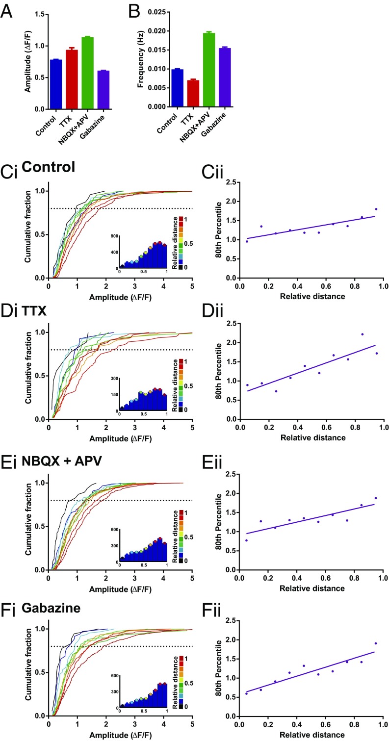
Where does this biased distribution of synapse function originate? A number of different explanations could account for the difference in mCaT signals observed along dendrites, including nonlinearities introduced by specific channels (e.g., VGCC, intracellular stores) (14, 15), biased distribution of NMDAR subtypes (e.g., NR2A vs. NR2B), or the shape of the spines themselves (16). Blockade of VGCC, AMPA/kainate, or ryanodine-sensitive intracellular stores had no effect on the biased distribution of mCaT amplitude (Fig. S6 A–D). We also saw no effect in the distribution of responses when selectively blocking NR2B receptors (Fig. S6E), even though there was a significant decrease in both the amplitude and frequency of events (Fig. S6F). Finally, we explored the possibility that the biased distribution of mCaT signals along dendrites is driven by neuronal or synaptic activity (Fig. 4). Dissociated neurons were treated with either TTX (1 μM) or gabazine (10 μM) to silence or increase neuronal activity in the network, respectively. In addition, we also treated another set of neurons with 2,3-dihydroxy-6-nitro-7-sulfamoyl-benzo[f]quinoxaline-2,3-dione (NBQX) and APV to silence both AMPA and NMDAR synaptic transmission. All treatments were performed during a period of synapse maturation in vitro [from 10 to 17 d in vitro (DIV)]. We found that silencing network activity with NBQX/APV treatment caused a significant increase in the amplitude of mCaTs, whereas increasing network activity with gabazine caused a reduction in mCaT amplitude. TTX treatment, however, did not show a significant change in amplitude, although a trend toward larger events was observed. However, despite observing changes in synaptic properties, we found no change in the spatial distribution of mCaT amplitude along dendrites by any of the treatments, showing that the biased distribution of synapse function is not driven by neuronal or synaptic activity (Fig. 4). These results suggest that intrinsic cellular properties, independent of activity, are responsible for the biased distribution of synapses described above.
Fig. S6.
mCaT distribution is unaffected by blocking AMPA receptors, ryanodine receptors, VGCCs, or GluN2B receptor subtypes. (A–Ei) Cumulative frequency distributions for mCaT amplitude for each spine where each plot is color matched to a different bin for relative distance as shown in the key to the Right. (A) Treated with 10 μM NBQX, n = 793 spines from 3 cells; (B) treated with 30 μM ryanodine, n = 450 spines from 3 cells; (C) treated with 500 nM SNX-482, n = 750 spines from 5 cells; (D) treated with a mixture of VGCC antagonists (1 μM nifedipine, 0.15 μM ω-Aga-TK, 3 μM ω -Cono-GVIA, 1 μM SNX, and 10 μM TTA-P2), n = 4,520 mCaTs from 3 cells; and (E) pretreated with 1 μM Ro 25-6981, n = 735 mCaTs from 3 cells. (A–Eii) The 80th percentile values for mCaT amplitude obtained from the cumulative frequency graphs, plotted as a function of relative distance. Spearman’s coefficient; NBQX, P = 0.007, R2 = 0.73; ryanodine, P = 0.0003, R2 = 0.82; SNX-482, P = 0.002, R2 = 0.77; VGCC antagonists P = 0.0005; Ro 25-6981, P = 0.005, R2 = 0.69. (F) Average mean amplitude (i) and frequency (ii) in control cells vs. cells pretreated with Ro 25-6981. For amplitude: control, n = 2,026 mCaTs from 4 cells, Ro 25-6981, n = 735 mCaTs from 3 cells, Mann–Whitney, P < 0.0001. For frequency: control, n = 1,041 spines from 4 cells, Ro 25-6981, n = 1,052 spines from 3 cells; Mann–Whitney, P < 0.0001.
Fig. 4.
mCaT amplitude continues to scale with relative distance following chronic changes in network activity. (A) Amplitude per spine following 7-d treatments with 1 μM TTX, 10 μM NBQX plus 50 μM APV, and 10 μM gabazine. Control, n = 1,733; TTX, n = 426; NBQX plus APV, n = 1,718; gabazine, n = 1,454. Kruskal–Wallis one-way ANOVA, P < 0.0001; Dunn’s multiple comparisons, all comparisons, P < 0.0001, excepting control vs. TTX, which was nonsignificant. (B) Frequency per spine following treatments as above. Control, n = 3,453; TTX, n = 1,374; NBQX plus APV, n = 2,371; gabazine, n = 2,246. Kruskal–Wallis one-way ANOVA, P < 0.0001; Dunn’s multiple comparisons, all comparisons, P < 0.0001. (C–Fi) Cumulative frequency distributions for mean mCaT amplitude per spine following no treatment (C) or treatment with 1 μM TTX (D), 10 μM NBQX plus 50 μM APV (E), or 10 μM gabazine (F). Each plot is color matched to a different bin for relative distance, as shown in the key to the Right of each plot. Inset histograms show the number of spines included within each relative distance bin. (C–Fii) The 80th percentile values for mCaT amplitude obtained from the cumulative frequency graphs, plotted as a function of relative distance. Spearman’s coefficient, control, P = 0.005; TTX, P = 0.0003; NBQX plus APV, P = 0.007; and gabazine, P = 0.0002; n numbers as given in A.
Distribution of Postsynaptic Structures Along Dendrites.
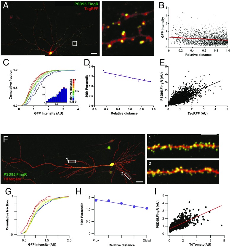
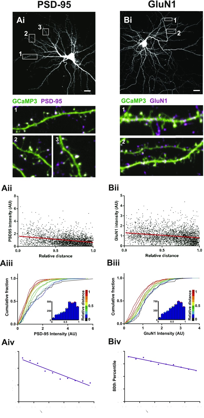
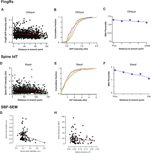
Next, we turned to investigate whether structural components of the synapse itself could affect spine calcium transients, and whether these structural features themselves are also systemically altered with dendritic position. To investigate the structure of postsynaptic spines and relate it to the functional measurements described above, we performed experiments that allowed us to characterize the distribution of postsynaptic density (PSD) size along dendrites. For this purpose we used fibronectin intrabodies generated with mRNA display (FingRs) to visualize the distribution of PSD-95 in vitro and in vivo, a technique recently shown to report endogenous levels of PSD-95 without any effect on synapse function (17). We found that neurons coexpressing a red fluorescent protein (either TagRFP or tdTomato) and PSD-95 FingR-EGFP showed green puncta along red dendrites that mainly localized to the tips of dendritic spines (Fig. 5A). The fluorescence intensity of PSD-95 FingR-EGFP showed a negative correlation with relative distance (Fig. 5 B–D), which also matched the correlation observed when PSD-95 or GluN1 were labeled by means of immunofluorescence staining (Fig. S7). In addition, sections of fixed brain tissue obtained from the CA1 region of the hippocampus following in utero electroporation of both constructs, resulted in a strong label of postsynaptic compartments by FingR-EGFP, also localized to dendritic spines, in postnatal day 21 (P21) pyramidal neurons (Fig. 5F). Analysis of the distribution of fluorescence intensity of FingR-EGFP showed a similar negative correlation with distance in basal dendrites (Fig. 5 G and H), as well as in oblique dendrites (Fig. S8 A–C), which was matched by a decrease in TdTomato florescence intensity in spines (Fig. S8 D–F). Not surprisingly, there was also a strong correlation between FingR-EGFP and TagRFP or TdTomato fluorescence (Fig. 5 E and I), mirroring the known correlation between PSD size and spine volume (18, 19). Importantly, we find that both dissociated neurons as well as neurons in the intact brain show a similar synaptic distribution along dendritic trees, strongly suggesting that this is a cell-autonomous feature that does not depend on the identity of synaptic inputs.
Fig. 5.
Postsynaptic strength inversely scales with relative distance both in vitro and in vivo. (A–D) Characterization of PSD-95.FingR-EGFP in dissociated hippocampal neurons. (A) Neuron coexpressing TagRFP (red) and PSD-95.FingR-EGFP (green). White box corresponds to the area shown in the zoomed region to the Right. (Scale bar, 20 μm.) (B) Plot of PSD-95.FingR intensity as a function of relative distance. Spearman’s correlation, P < 0.0001, n = 2639. (C) Cumulative frequency distributions for PSD-95.FingR-EGFP intensity for each spine where each plot is color matched to a different bin for relative distance shown in the key to the Right. Inset histograms show the number of spines included within each relative distance bin; n = 2,639 spines. (D) The 80th percentile values for PSD-95.FingR-EGFP intensity obtained from the cumulative frequency graphs, plotted as a function of relative distance. Spearman’s coefficient, P = 0.0007. (E) PSD-95.FingR-EGFP fluorescence plotted against spine TagRFP intensity. Spearman’s correlation, P < 0.0001, n = 2,695 spines. (F–I) Characterization of PSD-95.FingR-EGFP in basal dendrites of CA1 pyramidal cells (P21). (F) CA1 pyramidal cell coexpressing tandem-Tomato (red) and PSD-95.FingR-EGFP (green). Numbered white rectangles correspond to the zoomed regions shown on the Right. (Scale bar, 25 μm.) (G) Cumulative frequency distributions for spine PSD-95.FingR-EGFP intensity located at different locations within a branch. Plots are color coded so that warmer colors correspond to more distal locations. Spearman’s correlation between fluorescence intensity and distance to branch point r = −0.13, P < 0.0001, and n = 1,049 spines. (H) The 80th percentile values for spine PSD-95.FingR-EGFP intensity obtained from the cumulative frequency graphs shown in F, plotted as a function of distance to the branch point. (I) Spine PSD-95.FingR-EGFP fluorescence plotted against corresponding tandem-Tomato fluorescence intensity. Spearman’s correlation, r = 0.77, P < 0.0001.
Fig. S7.
Postsynaptic proteins inversely scale with relative distance. Immunocytochemical stains using antibodies against PSD-95 (A) and GluN1 (B) in dissociated hippocampal neurons. (A–Bi) Example hippocampal neurons expressing GCaMP3. White boxes correspond to the areas shown in the zoomed regions below, numbered appropriately. (Scale bars, 10 μm.) Zoomed regions show immunostain (magenta) overlaid onto the GCaMP3-expressing cell (green). (A–Bii) Postsynaptic immunostain intensity for each spine plotted as a function of relative distance. Spearman’s correlation, P < 0.0001 for all graphs. (A–Biii) Cumulative frequency distributions for immunostain intensity for each spine, where each plot is color matched to a different bin for relative distance shown in the key to the Right. Inset histograms show the number of spines included within each relative distance bin. (A–Biv) The 80th percentile values for immunostain intensity obtained from the cumulative frequency graphs, plotted as a function of relative distance. Spearman’s coefficient: PSD-95, P < 0.0001; GluN1, P < 0.0001. PSD-95, n = 2,720 spines from 4 cells; GluN1, n = 2,956 spines from 5 cells.
Fig. S8.
Structural measures of dendritic spines and shafts. (A) Plot of PSD-95.FingR intensity as a function of distance to branch point for oblique apical dendritic branches. Spearman’s correlation, r = −0.14; P < 0.0001; n = 927 spines. (B) Cumulative frequency distributions for spine PSD-95.FingR GFP fluorescent intensity located at different locations within a branch. Plots are color coded so that warmer colors correspond to more distal locations. (C) The 80th percentile values for spine PSD-95.FingR GFP intensity obtained from the cumulative frequency graphs shown in B, plotted as a function of distance to the branch point. (D) Plot of dendritic tdT fluorescence intensity as a function of distance to branch point for basal dendrites. Spearman’s correlation, r = −0.11; P < 0.0001; n = 1,049 spines. (E) Cumulative frequency distributions for spine tdT fluorescence intensity located at different locations within a basal branch. Plots are color coded so that warmer colors correspond to more distal locations. (F) The 80th percentile values for spine tdT fluorescence intensity obtained from the cumulative frequency graphs shown in E, plotted as a function of distance to branch point. (G) Data obtained from the SBF-SEM reconstructions shown in Fig. 4. Plot of spine neck length as a function of neck diameter shows the two variables are inversely correlated. Spearman’s correlation, r = −0.23, P = 0.024. (H) Spine neck resistance was found to be inversely correlated with spine volume, suggesting that smaller spines have necks with larger resistance and are therefore better isolated form the principal dendritic shaft. Spearman’s correlation, r = −0.38; P < 0.001. Neck resistance (Rneck) was calculated using Ohm’s law: , where L is the length of the spine neck, A is the cross-sectional area of the neck, and is the resistivity of the cytoplasm, which was assumed to be 150 Ω⋅cm.
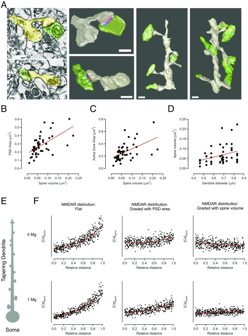
Because the distributions of structural components were often better correlated with relative distance compared with absolute distance from the cell body, we explored the possibility that local dendritic properties, such as dendrite diameter, may be responsible for controlling synapse strength. To obtain high-resolution measurements of dendrites and synapses, we performed serial block-face scanning electron microscopy in the stratum oriens of CA1 hippocampal neurons (Fig. 6A). As expected, reconstructions of basal dendrites showed a strong correlation between spine volume and either PSD area (Fig. 6B) or active zone area (Fig. 6C). More importantly, we also saw a significant correlation between dendrite diameter and spine volume (Fig. 6D). Interestingly, we also observe an inverse relation between spine head volume and spine neck resistance (Fig. S8 G and H), suggesting that smaller spines have necks with a higher resistance that will restrict the diffusion of ions to and from the dendritic shaft. Together, our data strengthen the idea that local dendritic properties can act as an important determinant of synapse structure, which helps explain the distance-dependent correlations we observe along tapering dendrites.
Fig. 6.
Presynaptic and postsynaptic elements are tightly correlated and follow dendrite diameter. (A–D) Serial block-face scanning electron microscopy (SBF-SEM) was used to reconstruct synapses on basal dendrites of CA1 neurons. (A) Single-section EM micrographs (Left Top and Bottom) of individual synapses with the postsynaptic compartment in yellow and presynaptic in green. Right panels show the same synapses reconstructed in 3D with PSD in red and active zone in blue. Further Right are two example dendrites (gray) that were reconstructed with their presynaptic boutons (green) and included in the analysis. (B–D) Quantification of presynaptic and postsynaptic features, n = 93 synapses and 17 dendrites. (B) Spine volume scales with PSD area (Spearman’s coefficient, R = 0.7, P < 0.0000001) and (C) with active zone area (Spearman’s coefficient, R = 0.43, P = 0.00002). (D) PSD area scales with spine volume (Spearman’s coefficient, R = 0.71, P < 0.0000001). (D) Spine volume correlates with dendrite diameter (Spearman’s coefficient, R = 0.25, P = 0.014). (All scale bars: 500 nm.) (E) Schematic representation of the computational model, consisting of a neuron with a tapering dendrite and spines that scale down in size with distance from the soma. (F) Results from model plotting mCaT amplitude as a function of relative distance. The Top three graphs represent the model run in absence of Mg and the Bottom three in the presence of Mg. The two graphs on the Left show results of the model when the distribution of NMDAR that is constant (flat) with distance and spine size. The Middle two graphs show a model where NMDARs scale with surface area and the two graphs on the Right show a model where NMDARs scale with spine volume. The red line is a best-fit polynomial curve to the points.
Spine head volume and spine neck resistance could have an important impact on calcium concentration and therefore help explain why larger mCaTs are found in more distal domains where spine volume is decreased (16). To directly measure the relationship between spine volume and mCaT amplitude, we simultaneously measured spine volume and mCaTs in the same spines for both dissociated neurons and organotypic slices in neurons coexpressing TagRFP and GCaMP3 (Fig. S9). We found that TagRFP fluorescence measured at the spine, and thought to be proportional to spine volume (20), decreased with relative distance (Fig. S9 A, B, E, and F, and confirmed with spines expressing EGFP in Fig. S9H), whereas mCaT amplitude increased (Fig. 3). A plot of mCaT amplitude as a function of TagRFP fluorescence showed a nonlinear, inverse relationship between the two variables (Fig. S9 C, D, and G), in agreement with previous studies, suggesting that smaller spines have larger mCaTs (16, 20–22).
Fig. S9.
Spine volume decreases approaching branch tips. (A) Cumulative frequency distributions for TagRFP intensity for each spine recorded in in dissociated hippocampal cultures where each plot is color matched to a different bin for relative distance as shown in the key to the Right. Inset histograms show the number of spines included within each relative distance bin, n = 1,938 spines from 4 cells. (B) The 80th percentile values for TagRFP intensity obtained from the cumulative frequency graphs, plotted as a function of relative distance. Spearman’s coefficient; P < 0.0001. (C) Cumulative frequency distributions for mCaT amplitude, where each plot is color matched to a different bin for TagRFP spine intensity as shown in the key to the Right. Inset histograms show the number of spines included within each relative distance bin; n = 3,114 mCaTs from 4 cells. (D) The 80th percentile values for TagRFP intensity obtained from the cumulative frequency graphs, plotted as a function of relative distance. Spearman’s coefficient; P = 0.0008. (E) Cumulative frequency distributions for TagRFP intensity for each spine recorded in in organotypic hippocampal slice, where each plot is color matched to a different bin for relative distance as shown in the key to the Right. Inset histograms show the number of spines included within each relative distance bin, n = 603 spines from three cells. (F) The 80th percentile values for TagRFP intensity obtained from the cumulative frequency graphs, plotted as a function of relative distance. Spearman’s coefficient; P = 0.002. (G) Amplitude as a function of spine TagRFP intensity for spines obtained from organotypic slices. Spearman’s coefficient, P < 0.0001. (H) Plot of cytoplasmic EGFP intensity as a function of distance to branch point for basal dendritic branches in CA1 neurons from organotypic slices. Spearman’s correlation, r = −0.3; P < 0.0001; n = 679 spines.
A Computational Model of NMDAR-Driven Calcium Signals Along Tapering Dendrites.
Our findings show that dendritic spines become smaller toward dendritic tip ends, resulting in larger calcium concentrations in distal dendrites. A model using the structural features of the dendrite and spines found in this study was used to recreate calcium signals in single dendritic spines along a tapering dendrite (Fig. 6 E and F). In our model, dendritic spines volume, as well as AMPAR number, decreased toward tip ends in agreement with our findings (Fig. 6 A–D and Fig. S9). Previous findings have established a strong correlation between spine volume and both PSD size, as well as AMPA receptors number (18, 19), but the link with NMDARs is less clear. We were interested to see whether the mCaT distributions observed experimentally could be explained by systematically varying NMDAR numbers and spine size. In our model, we varied the distribution of NMDARs to cover three different scenarios: (i) where NMDAR numbers were kept constant at all volumes of spines along a dendrite; (ii) where NMDAR numbers decreased proportionally to PSD size, rather than volume; and (iii) where NMDAR number decreased proportionally to spine volume. Finally, we run the model either in the absence of Mg2+ (as in our experimental procedure) or in presence or of 1 mM Mg2+. In the absence of Mg2+, we found that, in the first two models, where NMDAR numbers are flat or decrease proportionally with PSD size rather than follow spine volume, the calcium signals elicited by the spontaneous release of neurotransmitter became larger toward dendritic tip ends where smaller spines are found (Fig. 6F). Even though a flat distribution of NMDARs (model 1) showed a stronger distance-dependent increase in calcium signals than model 2, both models are examples of how mismatches in decreases in spine volume and number of NMDARs result in increases in calcium concentration. In agreement with this, when the number of NMDARs decrease in accordance with spine volume, the distance-dependent increase in mCaT amplitude was lost. Immunostaining experiments indicated that NMDAR levels decrease with relative distance (Fig. S7B) less steeply than PSD95 levels (Fig. S7A), suggesting that NMDARs in fact undercompensate for changes in PSD size, suggestive of a scenario between model 1 and model 2. When we run the same models in the presence of Mg2+, the difference between proximal and distal calcium levels was exacerbated for the first two “undercompensating” models due to the more efficient recruitment of NMDARs in the thin, high-impedance domains of distal dendrites compared with thick proximal ones. The same model performed on nontapering dendrites gave very similar results. We conclude that NMDAR numbers do not scale with spine volume. Instead, the number of NMDARs undercompensate for changes in volume resulting in an increase in NMDAR-driven calcium responses in the smaller spines observed in distal dendrites. Because our data were obtained in the absence of Mg2+, we believe that our measures are an underestimate of the real differences in NMDAR-driven calcium signals along a dendrite that would normally occur in the presence of Mg2+ and further underscore the importance of our findings.
Discussion
The impact that a synapse has on neuronal output will depend on its strength, as well as its position on a dendrite. Here, we use a combination of different techniques to measure the structure and function of postsynaptic spines and show that the distribution of synapses along the dendritic tree of hippocampal neurons is biased, so that dendritic tip ends are more likely to contain smaller postsynaptic compartments. Surprisingly, and as a result of a negative correlation between spine size and NMDAR calcium signals, we found that quantal calcium responses (mCaTs) were larger when moving toward thinner distal dendrites, indicative of a nonlinear relationship between NMDAR number and spine volume. These findings show that spatial location, driven by the local properties of the dendrite, are important determinants of NMDAR calcium signals in individual spines and suggest that the rules governing synaptic plasticity may also be strongly influenced by dendritic position.
Biased Distribution of NMDAR-Driven Calcium Response Along Dendrites.
We have exploited the use of a genetically encoded calcium sensor to measure spontaneous calcium transients driven by the activation of NMDARs in single spines. We found that mCaT amplitude was highly heterogeneous within single spines. This is in agreement with previous studies showing that synaptic activation of NMDARs, either by local stimulation of presynaptic afferents or by single spine uncaging of caged glutamate, has a high CV (16, 20, 21). Although some of this variability has been proposed to be presynaptic (23), we found that the origin of our variability was mainly postsynaptic. Uncaging experiments that bypassed presynaptic neurotransmitter release showed similar levels of variability to those driven by spontaneous glutamate release. The most likely source of this variability is the low numbers of open NMDARs (one or less on average) at individual spines during synaptic activation (20), such that stochastic binding of glutamate to its receptor becomes an important source of noise (24).
More importantly for this study, we found that the amplitude of mCaTs was highly heterogeneous across different spines and showed an apparent negative correlation with spine size. Although spines along dendrites showed a gradual decrease in size toward tip ends, the calcium signal elicited by the quantal activation of NMDARs increased, suggesting a more complicated relationship between spine structure and synaptically driven calcium concentration. Whereas previous studies showed a strong correlation between spine size and AMPAR number (18, 19), NMDAR number has generally been found to be either independent or only weakly dependent on spine size (16, 20). As a result, it is likely that spines do not compensate for increases in volume by adding a proportional number of NMDARs to keep calcium levels constant across all spine sizes (25). In this scenario, small spines would, on average, be expected to show larger calcium concentrations than larger spines and, indeed, calcium measurements in response to NMDAR activation have been shown to inversely correlate with spine volume, although generally quite loosely (Fig. S9) (16, 20–22). It has also been proposed that spine neck geometry can also account for this negative correlation, where spines with smaller heads are thought to have thinner spine necks (Fig. S8 G and H) (26, 27) that restrict calcium diffusion, resulting in increased calcium concentration in the spine head (16). This may also help explain our findings, where smaller distal spines with narrower necks showed larger calcium transients. However, there may be additional differences between spines in different dendritic locations that could also contribute to the distribution observed here, although we tested the most plausible candidates (such as intracellular stores, NMDAR subunits, calcium channels, and AMPA receptors) and found them not to be involved. The most likely explanation for this negative correlation is an inverse relationship between spine volume and NMDAR number, which further suggests that the distribution of NMDARs along a dendrite undercompensates for increases in spine volume (Fig. 6).
Spine Size Distribution Along Dendrites.
One striking finding from our data is that, regardless of the hippocampal preparation used, synapses were biased toward smaller sizes in thinner distal dendrites. This is true for both dissociated neurons as well as neurons from the intact brain, suggesting a cell-autonomous feature that is independent of the network or the identity of the input. Furthermore, we find that these rules are independent of network activity levels, again suggesting an intrinsic cellular property occurring independently of synaptic activity. The effect of this inhomogeneity of spine volume is thought to be highly important in the integration of electrical signals. It has been suggested that distal inputs are weaker (smaller spines with fewer AMPA receptors) to compensate for the increase in input impedance along a tapering dendrite, allowing all synapses to contribute equally to local dendritic integration (28). In fact, the data presented here agree that the overall size of spines correlates well with dendrite diameter and helps explain why dendritic distance results in such a powerful determinant of synapse strength (28). In addition, we have shown that the dendritic position of synapses will also have a big effect on chemical signals, such as calcium influx. The mechanisms used to achieve this distance-dependent distribution in synapses are unclear, although it is worth noting that the rules that govern spike-timing dependent plasticity (STDP) differ with distance from the soma and may therefore affect synaptic properties locally (29, 30). Distal synapses are less prone to potentiation and have a longer window for long-term depression (LTD) than proximal ones, which could result in smaller distal synapses. The functional outcome of this distribution may therefore provide a form of local dendritic homeostasis that helps keep the strength of synaptic transmission and synaptic plasticity at all synapses equal, regardless of their position on the dendrite.
A Role for the Biased Distribution of Synaptic Inputs Along Dendritic Trees.
What purpose do the larger calcium signals in the smaller distal spines serve? It is tempting to speculate that differences in calcium along a dendrite may underlie differences in the types of plasticity that are favored in different compartments or in the actual rules that govern synaptic plasticity. Importantly, the amplitude of spine calcium signals are thought to determine the direction of long-term plasticity events (31). Whereas large spine calcium rises induced by high-frequency stimulation are thought to favor long-term potentiation, smaller calcium rises caused by low-frequency stimulation are more likely to result in LTD. As a result, spines that experience different calcium amplitudes should undergo different forms of plasticity. Furthermore, because the amplitude of calcium rises during long-term forms of plasticity arise from a combination of backpropagating action potentials (bAPs) and activation of NMDARs, differences in any of these two variables along a dendrite can affect plasticity rules. For example, there is strong evidence that STDP rules do differ depending on dendritic location (29, 30, 32), although this is generally thought to arise from the properties of the bAP. Distal spines experience smaller bAP depolarizations through a combination of passive decay and activation of voltage-gated conductances (e.g., A-type K+ conductances), resulting in smaller NMDAR-dependent calcium transients, in turn affecting local plasticity rules. It is therefore possible that the observed increase in the levels of calcium elicited by the activation of NMDARs at distal inputs act to compensate, at least in part, for the decrease in bAP amplitude. Interestingly, unlike pyramidal cells, aspiny hippocampal interneurons show a distance-dependent increase in bAP calcium signals along principal dendrites, suggesting an alternative form of compensatory mechanism may be in place in these neurons. Understanding how the different events that lead to rises in calcium at the spine come together at different dendritic location will be important for understanding the long-term plasticity rules that drive each dendritic site.
The fact that smaller spines display larger calcium transients may also help explain the higher rates of turnover experienced by small spines (33). The amplification of calcium signals in small spines could cause them to be more plastic and experience constant remodeling, even under basal levels of synaptic transmission. If this were the case, then spine turnover should increase gradually with distance along a dendrite, as spines decrease in size. Although not yet explored, this relationship between turnover and distance could provide interesting findings on the behavior of spines and their stability along dendrites. Not surprisingly, there are a number of possible outcomes to the biased distribution of calcium signals along a dendritic tree. It now remains to be established what purpose they serve and how this biased distribution is achieved by a cell.
Materials and Methods
All animal procedures were approved by the King's College London local ethics committee and the United Kingdom Home Office. All pharmaceutical reagents were obtained from Sigma-Aldrich, unless otherwise stated.
Dissociated Hippocampal Cultures and Organotypic Slices.
Primary hippocampal cultures were prepared from embryonic day 18 Sprague–Dawley rats (Charles River Laboratory). Dissociated cells were plated onto 18-mm diameter coverslips (Menzel Gläser) pretreated with poly-d-lysine (50 μg/mL) and laminin (20 μg/mL) at a density of 350 cells per mm2 in Neurobasal media containing 1% FCS, 1% B-27 supplement, 0.5% glutamax, and 0.5% penicillin/streptomycin. Neurons were kept for 17–21 DIV. Organotypic hippocampal slice cultures were prepared as described previously (34). Briefly, the hippocampi of 7-d-old, male Sprague–Dawley rats (Charles River) were dissected in cold Gey’s balanced salt solution supplemented with d-glucose (34.7 mM) and cut into 400-μm-thick slices using a McIlwain tissue chopper. Slices were placed onto Millicell-CM membranes and maintained in culture media composed of 25% (vol/vol) Earle’s balanced salt solution, 49% (vol/vol) MEM, 1% B27 (all Invitrogen), 25% (vol/vol) heat-inactivated horse serum (PAA), and 6.2 g/L glucose (Fisher). Slices were incubated for a total of 6 DIV at 36 °C and 5% (vol/vol) CO2. After 1 DIV, slices were transfected using a Helios Gene Gun (Bio-Rad). The target DNA for both dissociated and organotypic cultures was synapsin:GCaMP3 and synapsin:TagRFP. This resulted in sparse transfection rates (typically less than 10 cells per slice), and recordings were performed at 7–12 DIV.
In Utero Electroporation.
In utero electroporation was carried out using a protocol adapted from ref. 35. Briefly, timed-pregnant C57BL/6J female mice were anesthetized with a mix of oxygen–isoflurane before the abdomen was opened and the uterine horns exposed. The DNA solution was injected into the lateral ventricle of embryonic day 14.5 embryos using a glass micropipette. Approximately 0.5–1.0 μL of a solution containing Tris⋅HCl (10 mM), EDTA (1 mM), Fast green dye [0.5% (wt/vol)], and a mixture (3:1 molar ratio) of PSD95.FingR-GFP and CAG:tdTomato plasmids (DNA concentration, ∼1 mg/mL) was injected. Five square electric pulses (40 V, 50 ms) were passed at 1-s intervals using a square-wave electroporator (CUY21EDIT; NEPA GENE). At P21, animals were transcardially perfused with 20 mL of ice-cold saline solution, followed by 20 mL of ice-cold 4% (wt/vol) PFA in 0.1 M phosphate buffer. The brains were carefully removed and put in 4% (wt/vol) PFA solution overnight at 4 °C. Coronal sections (100 μm thick) were obtained using a Leica VT1000S vibratome.
Live Imaging.
Imaging of mCaTs was mostly carried out in hippocampal dissociated cultures expressing GCaMP3 using an Olympus IX71 inverted microscope with a CCD camera (Coolsnap HQ) controlled by Slidebook software (Intelligent Imaging Innovations), equipped with a 40×/1.0 N.A. oil-immersion objective (Olympus). The excitation light source was a xenon-arc lamp (Lambda LS; Sutter Instruments), in which light exposure was regulated by a rapid shutter (smartShutter; Sutter Instruments) controlled by a Sutter Instruments lambda 10-3 controller. Filtering was provided by 470 ± 20-nm bandpass excitation and 515 ± 20-nm bandpass emission (Chroma Technology Corporation) filter sets. Functional time series were acquired at a rate of ∼6 Hz and 0.3 × 0.3-μm resolution. For wide-field imaging of TagRFP, 565 ± 22-nm bandpass excitation and 590-nm long-pass dichroic plus 650 ± 36-nm bandpass emission (Chroma Technology Corporation) filter sets were used. Some live imaging was also performed using a confocal microscope (FV1000 Olympus equipped with a 40×/0.8 N.A. water-immersion objective). Organotypic slices were transferred to an imaging chamber and superfused with oxygenated (95% O2/5% CO2) artificial cerebrospinal fluid (ACSF) [composition (in mM): 119 NaCl, 2.5 KCl, 2 CaCl2, 0 MgCl2, 1 NaH2PO4, 26.2 NaHCO3, 11 glucose, 0.01 serine, 2.2 Trolox] at 32–35 °C. Time-lapse images were carried out on neurons coexpressing GCaMP3 and tagRFP proteins, excited with 488- and 543-nm laser lines, respectively, and imaged with the appropriate filters. To keep imaging rates above 6 Hz, small dendritic portions were imaged, typically in the basal dendrites, which were closer to the surface of the slice. Due to the sporadic nature of gene gun transfection, neurons imaged include CA3 and entorhinal cortex pyramidal neurons identified by cellular morphology and location within the brain slice.
Dissociated neurons transfected with GCaMP3 were transferred into HBS containing the following (in mM): 139 NaCl, 2.5 KCl, 10 Hepes, 10 d-glucose, 2 CaCl2 with 0 Mg2+, and 1 μM TTX (Alomone) at 17–21 DIV. Confocal imaging was carried out as indicated for organotypic slices. Line scan imaging on dissociated neurons was performed by free-hand tracing along a dendritic branch, taking care to position the line over the center of multiple dendritic spines. Line scans were acquired at a rate of ∼125 Hz. Local uncaging of caged-glutamate was performed by adding caged MNI-glutamate (Tocris) to the bath (0.5 mM). Uncaging was performed using a 405-nm laser (4.69 mW, pulses between 0.02 and 0.5 ms) focused at a single point and positioned next to a dendritic spine. Repetitive stimuli of fixed duration were delivered every 15 s, for between 17 and 31 trails per spine. Images were acquired at 9–18 Hz. Stimulation of GCaMP3-expressing dissociated neurons was performed in a custom-made chamber fitted with a pair of parallel platinum electrodes, 5 mm apart, in HBS (supplemented with 25 µM APV and 20 µM CNQX). Neurons were stimulated by delivering 1-ms, 25-mA current pulses using an SD9 stimulator (Grass Instruments), whose timing was controlled by a TTL signal from the imaging software (Slidebook).
Pharmacology of mCaT Responses.
To test the pharmacological profile of mCaTs, HBS was supplemented with the following: 10 μM NBQX (Tocris), 500 nM SNX-482, or 30 µM ryanodine (Abcam). For VGCC mixture experiments, HBS was supplemented with 1 μM nifedipine, 0.15 μM ω-Aga-TK, 3 μM ω-Cono-G VIA, 1 μM SNX, and 10 μM TTA-P2. In each case, a baseline time series was followed 10 min later by a time series in the absence (control cells) or presence of the drug. Changes seen in amplitude or frequency in GCaMP3-expressing control cells mean that mCaT metrics are expressed either as per cell, or at each spine using the equation ((I2 − I1)/(I1 + I2)), where I1 is the amplitude or frequency before and I2 after drug application. For neurons expressing GCaMP6f (VGCC mixture experiment), no change in controls was seen; therefore, only before and after drug treatment data are shown. To test the role of the GluN2B subunit on mCaT amplitude along dendrites, neurons were pretreated with 1 μM Ro 25-6981 (Tocris) for 1 h at 37 °C. Homeostatic plasticity experiments were carried out by adding one of the following to the cell culture medium of GCaMP3-transfected neurons from 10 DIV until 17 DIV: 1 μM TTX, 10 μM gabazine, or 10 μM NBQX plus 25 μM APV for 1 wk. mCaTs were then imaged using wide-field microscopy, as described above.
Analysis of Spontaneous mCaTs.
mCaTs were analyzed using custom-written MATLAB routines. Briefly, small ROIs were drawn around dendritic spines identified by morphology. For each time series, background was chosen as an area away from the cell and was subtracted from the image. Baseline fluorescence for each ROI was calculated as the median fluorescence intensity from all time points to reduce contamination from calcium transient spikes. ΔF/F traces for each ROI were calculated and analyzed using MiniAnalysis software (Synaptosoft).
Although ΔF/F was adopted as our standard metric, alternative functional metrics were also tested. ΔG/R was taken from cells coexpressing GCaMP3 and TagRFP. The change in GCaMP fluorescence (ΔG) was normalized to the fluorescence intensity of TagRFP (R) for each ROI. Calcium concentration was estimated after calculating the minimum and maximum GCaMP3 fluorescence at each spine. Following the functional recording of mCaTs, cells were perfused in calcium-free HBS with 5 mM EGTA and 5 μM ionomycin to measure the minimum GCaMP3 fluorescence (Fmin). Cells were subsequently bathed in HBS with saturating calcium (10 mM) and ionomycin (5 μM) to record the maximum GCaMP3 fluorescence at each spine (Fmax). Calcium concentration was calculated using the following equation: 0.41 × ΔF/((Fmax − Fmin) − ΔF), where 0.41 is the Kd of GCaMP3 (16). When grouping measurements from multiple cells (e.g., mCaT amplitude, instantaneous frequency, immunofluorescence), variables were normalized to the mean value for each cell.
Dendritic structure was traced using the NeuronJ plugin for ImageJ to obtain the coordinates of branch positions. Using in-house MATLAB routines, each branch was stitched together and ROIs assigned to a parent branch dependent on the shortest distance between ROI coordinates and branch coordinates. Two distance metrics were used: absolute and relative distance to the soma. Absolute distance, which is the distance of each ROI to the cell soma, was calculated by an algorithm (Dijkstra’s algorithm), which searches for the shortest path along the branches to the cell body. Relative distance was calculated as the absolute distance divided by the distance from the soma to the furthest branch tip, calculated using an algorithm that searches for the longest path from each ROI to a branch tip. Variables are then binned into 10 equal-sized distance bins and displayed as cumulative histograms. A summary plot using the 80th percentile for each binning interval was chosen to illustrate the population trends across distance bins. All statistical tests were performed using MATLAB or GraphPad Prism.
Immunohistochemistry.
Dissociated hippocampal neurons expressing GCaMP3 were immunostained using the following primary antibodies: rabbit αPSD-95 (1:500; Millipore), mouse αGluN1 (1:100; Thermo Scientific), and chicken αGFP (1:1,000; Abcam). Neurons coexpressing PSD-95.FingR-EGFP and TagRFP were immunostained using a rabbit αtRFP (1:1,000; Evrogen) only, with no antibody needed to image the GFP signal. Briefly, neurons were fixed in 4% (wt/vol) PFA for 20 min and permeabilized using PBS supplemented with 0.25% Triton X-100 (Tx) for 5 min. Cells were blocked by incubation with 10% (vol/vol) goat serum for 1 h at room temperature. Cells were incubated with primary antibodies in 2% (vol/vol) goat serum overnight at 4 °C and in fluorophore-conjugated secondary antibodies for 1 h at room temperature. Coverslips were mounted onto glass microscope slides using Mowiol. Imaging of immunostained neurons was performed using an Olympus FV1000 confocal microscope equipped with a 40×/0.8 N.A. water-immersion objective (Olympus). Coronal brain sections containing CA1 pyramidal cells electroporated with PSD-95.FingR-EGFP and tandem-tomato fluorescent protein were immunostained using rabbit α-DsRed (1:2,000; Clontech) and chicken α-GFP (1:5,000, Abcam) primary antibodies. Sections were permeabilized in PBS-based solution containing 1% Tx for 1 h, followed by blocking in PBS containing 0.1% Tx, 10% (vol/vol) normal goat serum (NGS), and 1% BSA for 2 h. Sections were then incubated in primary antibodies in 0.1% Tx, 1% NGS, and 0.1% BSA for 2 d at room temperature, followed by incubation in fluorophore-conjugated secondary antibodies (1:1,000; Molecular Probes) diluted in the same solution for 2 h at room temperature, washed, and mounted using Vectashield mounting media. Cells were imaged using a Nikon A1 confocal microscope equipped with 40× water immersion objective (N.A., 1.15). Confocal stacks were acquired at 0.5-μm intervals; pixel size was 0.14 μm.
Analysis of in Utero Electroporated CA1 Pyramidal Cells Expressing PSD-95.FingR.
The distribution of PSD-95.FingR fluorescent intensities along individual branches of CA1 pyramidal cells was analyzed using custom-written IgorPro (Wavemetrics) routines. Briefly, small ROIs were drawn in individual confocal sections around dendritic spines identified by morphology in selected branches where no branch points were present. Maximum fluorescent intensities for both GFP and tandem-Tomato were obtained for each ROI from each Z slice of median 3D filtered image stacks. The Z position of the spine was determined as the section with maximum GFP fluorescence intensity. Dendritic structures were traced in 3D using the Simple Neurite Tracer plugin for ImageJ, creating an SWC text file containing the coordinates of branch nodes taken at regular 0.2-μm intervals. The Trees Toolbox MATLAB software package (36) was used to extract the distance from each node to the cell body along the dendritic structure. Coordinates for each ROI are imported and linked to the nearest branch node from where distance to cell body is extracted. GFP fluorescence was then binned into five equal-sized distance bins and displayed as cumulative histograms. A summary plot using the 75th percentile for each binning interval was chosen to illustrate the population trends across distance bins. The trees toolbox and associated algorithms outlined above also rendered 3D dendritic trees to measure distance variables in organotypic slices.
Serial Scanning Block Face Electron Microscope Imaging.
Mice (P21) were transcardially perfused with 20 mL of ice-cold saline solution followed by 200 mL of ice-cold fixative [2% (wt/vol) PFA and 0.2% glutaraldehyde mixture in 0.1 M phosphate buffer], followed by incubation overnight in fresh fixative at 4 °C. Coronal vibratome sections (60 μm) were cut using a Leica VT1000S vibratome and further fixed in 1.5% (wt/vol) potassium ferrocyanide:2% (wt/vol) osmium tetroxide in cacodylate buffer for 30 min at 4 °C. Tissue was then thoroughly rinsed in distilled water and incubated in 1% aqueous thiocarbohydrazide for 4 min. After further rinsing, the samples were treated with 2% (wt/vol) aqueous osmium tetroxide for 30 min, rinsed, and en bloc stained in 1% uranyl acetate for 2 h. To further enhance contrasts in the samples, one last treatment with Walton’s lead was carried out for 30 min at 60 °C, before proceeding to dehydration in an ethanol series and infiltration with Durcupan ACM resin. After embedding and curing, tissue blocks were mounted on Gatan 3View aluminum pins using conductive glue (CircuitWorks Conductive Epoxy) and trimmed accordingly. Before imaging, samples were gold coated to increase electron conductivity. The specimens were then placed inside a Jeol field emission scanning electron microscope (JSM-7100F) equipped with a 3View 2XP system (Gatan). Section thickness was set at 35 nm (Z resolution). Samples were imaged at 2.5 kV under high vacuum using a 2,048 × 2,048 scan rate, which gave a final pixel size of 4.9 nm.
Electron microscope images were registered and manually segmented using the ImageJ plugin TrakEM2 (37). Extracted 3D structures were exported to the Blender software, which was used to compute surface, volume, and length measurements and produce the rendered 3D reconstructions shown in Fig. 6.
Computer Simulations.
All simulations were implemented using MATLAB using standard compartmental modeling methods (38). A simplified “ball-and-stick” model neuron consisted of a spherical soma (50-μm diameter) and a single unbranched dendrite (250 μm long). The large soma size was chosen to give a somatic input resistance of 120 MΩ, to mimic the substantial impedance load of a full dendritic tree that we did not explicitly model. The dendrite diameter tapered linearly from proximal (0.8-μm diameter) to distal (0.4-μm diameter) to match our electron microscopy data (Fig. 6). The dendritic voltage was calculated in 5-μm segments along its entire length to ensure numerical accuracy. Synapses were placed randomly along the dendrite with locations drawn from a uniform distribution. Each synapse was located on a dendritic spine (neck length, 0.5 μm; neck diameter, 0.2 μm). The volume of each spine head depended on its dendritic location, with the most proximal spines having volumes of 0.1 μm3, linearly decreasing to a distal spine head volume of 0.05 μm3, in accordance with our electron microscopy data (Fig. 6). The membrane had only passive conductances with parameters as follows: axial resistivity, 200 Ω⋅cm; membrane capacitance, 0.75 μF/cm2; leak conductance density, 0.25 pS/μm3; leak reversal potential, −70 mV. Spine neck capacitances were left out as they were so small as to have negligible effect (spine head capacitances were included). The time course of AMPA receptors were modeled as the difference between two exponentials with τrise of 0.2 ms and τdecay of 2 ms. The time course of NMDARs were modeled similarly but with τrise of 2 ms and τdecay of 86 ms. The NMDAR Mg+ block was modeled according to ref. 39.
In accordance with our recorded data, total AMPAR conductance for each synapse in the model decreased with dendritic distance from soma. Although the biological number of AMPARs could not be estimated from our imaging data, we set AMPAR conductance to 2 nS proximally to 1 nS distally as it resulted in somatic excitatory postsynaptic potentials of reasonable amplitude for CA1 pyramidal neurons (0.7 mV proximal and 0.6 mV distal). Also in accordance with our data, we kept NMDA conductance at each synapse independent of dendritic location at 600 pS.
Spine [Ca2+] dynamics were modeled as a single variable per synapse with simple linear behavior. Spine Ca2+ concentration increased in proportion to local synaptic NMDAR current and inversely proportional to spine volume, and decreased linearly with a time constant of τCa = 14 ms to represent the combined effects of Ca2+ extrusion through membrane pumps and diffusion through the spine neck (40). Because this model of spine Ca2+ is phenomenological, the units of [Ca2+] are arbitrary. The equation for the dynamics is as follows:
where [Ca]i is the Ca2+ concentration of the ith spine, INMDA is the current through the synapse, Vsp is the spine volume, τCa is the calcium extrusion time constant, and η is a constant of proportionality.
Supplementary Material
Acknowledgments
We thank Don Arnold for providing the PSD-95 FingR DNA. We also thank Matthew Grubb for comments on the manuscript and the members of the J.B. Laboratory for helpful discussions and suggestions, Mideia Kotsogianni for technical help, and Robert Hindges for assistance with in utero electroporations. This work was funded by a Medical Research Council studentship (to A.S.W.) and a Wellcome Trust Investigator award, a European Research Council Consolidator grant, a Lister Prize Fellowship, and a European Commission Seventh Framework Programme DESIRE grant (to J.B.).
Footnotes
The authors declare no conflict of interest.
This article is a PNAS Direct Submission.
This article contains supporting information online at www.pnas.org/lookup/suppl/doi:10.1073/pnas.1607462114/-/DCSupplemental.
References
- 1.Megías M, Emri Z, Freund TF, Gulyás AI. Total number and distribution of inhibitory and excitatory synapses on hippocampal CA1 pyramidal cells. Neuroscience. 2001;102(3):527–540. doi: 10.1016/s0306-4522(00)00496-6. [DOI] [PubMed] [Google Scholar]
- 2.Koch C, Zador A. The function of dendritic spines: Devices subserving biochemical rather than electrical compartmentalization. J Neurosci. 1993;13(2):413–422. doi: 10.1523/JNEUROSCI.13-02-00413.1993. [DOI] [PMC free article] [PubMed] [Google Scholar]
- 3.Lisman J. A mechanism for the Hebb and the anti-Hebb processes underlying learning and memory. Proc Natl Acad Sci USA. 1989;86(23):9574–9578. doi: 10.1073/pnas.86.23.9574. [DOI] [PMC free article] [PubMed] [Google Scholar]
- 4.Malenka RC, Nicoll RA. Long-term potentiation—a decade of progress? Science. 1999;285(5435):1870–1874. doi: 10.1126/science.285.5435.1870. [DOI] [PubMed] [Google Scholar]
- 5.Evans RC, Blackwell KT. Calcium: Amplitude, duration, or location? Biol Bull. 2015;228(1):75–83. doi: 10.1086/BBLv228n1p75. [DOI] [PMC free article] [PubMed] [Google Scholar]
- 6.Matsuzaki M, Honkura N, Ellis-Davies GC, Kasai H. Structural basis of long-term potentiation in single dendritic spines. Nature. 2004;429(6993):761–766. doi: 10.1038/nature02617. [DOI] [PMC free article] [PubMed] [Google Scholar]
- 7.Abrahamsson T, Cathala L, Matsui K, Shigemoto R, Digregorio DA. Thin dendrites of cerebellar interneurons confer sublinear synaptic integration and a gradient of short-term plasticity. Neuron. 2012;73(6):1159–1172. doi: 10.1016/j.neuron.2012.01.027. [DOI] [PubMed] [Google Scholar]
- 8.Murthy VN, Sejnowski TJ, Stevens CF. Dynamics of dendritic calcium transients evoked by quantal release at excitatory hippocampal synapses. Proc Natl Acad Sci USA. 2000;97(2):901–906. doi: 10.1073/pnas.97.2.901. [DOI] [PMC free article] [PubMed] [Google Scholar]
- 9.Mackenzie PJ, et al. Ultrastructural correlates of quantal synaptic function at single CNS synapses. J Neurosci. 1999;19(12):RC13. doi: 10.1523/JNEUROSCI.19-12-j0003.1999. [DOI] [PMC free article] [PubMed] [Google Scholar]
- 10.Kay L, Humphreys L, Eickholt BJ, Burrone J. Neuronal activity drives matching of pre- and postsynaptic function during synapse maturation. Nat Neurosci. 2011;14(6):688–690. doi: 10.1038/nn.2826. [DOI] [PubMed] [Google Scholar]
- 11.Fredj NB, Burrone J. A resting pool of vesicles is responsible for spontaneous vesicle fusion at the synapse. Nat Neurosci. 2009;12(6):751–758. doi: 10.1038/nn.2317. [DOI] [PMC free article] [PubMed] [Google Scholar]
- 12.Murthy VN, Stevens CF. Reversal of synaptic vesicle docking at central synapses. Nat Neurosci. 1999;2(6):503–507. doi: 10.1038/9149. [DOI] [PubMed] [Google Scholar]
- 13.Rose T, Schoenenberger P, Jezek K, Oertner TG. Developmental refinement of vesicle cycling at Schaffer collateral synapses. Neuron. 2013;77(6):1109–1121. doi: 10.1016/j.neuron.2013.01.021. [DOI] [PubMed] [Google Scholar]
- 14.Bloodgood BL, Sabatini BL. Nonlinear regulation of unitary synaptic signals by CaV(2.3) voltage-sensitive calcium channels located in dendritic spines. Neuron. 2007;53(2):249–260. doi: 10.1016/j.neuron.2006.12.017. [DOI] [PubMed] [Google Scholar]
- 15.Emptage N, Bliss TV, Fine A. Single synaptic events evoke NMDA receptor-mediated release of calcium from internal stores in hippocampal dendritic spines. Neuron. 1999;22(1):115–124. doi: 10.1016/s0896-6273(00)80683-2. [DOI] [PubMed] [Google Scholar]
- 16.Noguchi J, Matsuzaki M, Ellis-Davies GC, Kasai H. Spine-neck geometry determines NMDA receptor-dependent Ca2+ signaling in dendrites. Neuron. 2005;46(4):609–622. doi: 10.1016/j.neuron.2005.03.015. [DOI] [PMC free article] [PubMed] [Google Scholar]
- 17.Gross GG, et al. Recombinant probes for visualizing endogenous synaptic proteins in living neurons. Neuron. 2013;78(6):971–985. doi: 10.1016/j.neuron.2013.04.017. [DOI] [PMC free article] [PubMed] [Google Scholar]
- 18.Matsuzaki M, et al. Dendritic spine geometry is critical for AMPA receptor expression in hippocampal CA1 pyramidal neurons. Nat Neurosci. 2001;4(11):1086–1092. doi: 10.1038/nn736. [DOI] [PMC free article] [PubMed] [Google Scholar]
- 19.Zito K, Scheuss V, Knott G, Hill T, Svoboda K. Rapid functional maturation of nascent dendritic spines. Neuron. 2009;61(2):247–258. doi: 10.1016/j.neuron.2008.10.054. [DOI] [PMC free article] [PubMed] [Google Scholar]
- 20.Nimchinsky EA, Yasuda R, Oertner TG, Svoboda K. The number of glutamate receptors opened by synaptic stimulation in single hippocampal spines. J Neurosci. 2004;24(8):2054–2064. doi: 10.1523/JNEUROSCI.5066-03.2004. [DOI] [PMC free article] [PubMed] [Google Scholar]
- 21.Sobczyk A, Scheuss V, Svoboda K. NMDA receptor subunit-dependent [Ca2+] signaling in individual hippocampal dendritic spines. J Neurosci. 2005;25(26):6037–6046. doi: 10.1523/JNEUROSCI.1221-05.2005. [DOI] [PMC free article] [PubMed] [Google Scholar]
- 22.Noguchi J, et al. In vivo two-photon uncaging of glutamate revealing the structure-function relationships of dendritic spines in the neocortex of adult mice. J Physiol. 2011;589(Pt 10):2447–2457. doi: 10.1113/jphysiol.2011.207100. [DOI] [PMC free article] [PubMed] [Google Scholar]
- 23.Franks KM, Stevens CF, Sejnowski TJ. Independent sources of quantal variability at single glutamatergic synapses. J Neurosci. 2003;23(8):3186–3195. doi: 10.1523/JNEUROSCI.23-08-03186.2003. [DOI] [PMC free article] [PubMed] [Google Scholar]
- 24.Franks KM, Bartol TM, Jr, Sejnowski TJ. A Monte Carlo model reveals independent signaling at central glutamatergic synapses. Biophys J. 2002;83(5):2333–2348. doi: 10.1016/S0006-3495(02)75248-X. [DOI] [PMC free article] [PubMed] [Google Scholar]
- 25.O’Donnell C, Nolan MF, van Rossum MC. Dendritic spine dynamics regulate the long-term stability of synaptic plasticity. J Neurosci. 2011;31(45):16142–16156. doi: 10.1523/JNEUROSCI.2520-11.2011. [DOI] [PMC free article] [PubMed] [Google Scholar]
- 26.Arellano JI, Benavides-Piccione R, Defelipe J, Yuste R. Ultrastructure of dendritic spines: Correlation between synaptic and spine morphologies. Front Neurosci. 2007;1(1):131–143. doi: 10.3389/neuro.01.1.1.010.2007. [DOI] [PMC free article] [PubMed] [Google Scholar]
- 27.Harris KM, Jensen FE, Tsao B. Three-dimensional structure of dendritic spines and synapses in rat hippocampus (CA1) at postnatal day 15 and adult ages: Implications for the maturation of synaptic physiology and long-term potentiation. J Neurosci. 1992;12(7):2685–2705. doi: 10.1523/JNEUROSCI.12-07-02685.1992. [DOI] [PMC free article] [PubMed] [Google Scholar]
- 28.Katz Y, et al. Synapse distribution suggests a two-stage model of dendritic integration in CA1 pyramidal neurons. Neuron. 2009;63(2):171–177. doi: 10.1016/j.neuron.2009.06.023. [DOI] [PMC free article] [PubMed] [Google Scholar]
- 29.Froemke RC, Poo MM, Dan Y. Spike-timing-dependent synaptic plasticity depends on dendritic location. Nature. 2005;434(7030):221–225. doi: 10.1038/nature03366. [DOI] [PubMed] [Google Scholar]
- 30.Letzkus JJ, Kampa BM, Stuart GJ. Learning rules for spike timing-dependent plasticity depend on dendritic synapse location. J Neurosci. 2006;26(41):10420–10429. doi: 10.1523/JNEUROSCI.2650-06.2006. [DOI] [PMC free article] [PubMed] [Google Scholar]
- 31.Lisman JE. A mechanism for memory storage insensitive to molecular turnover: A bistable autophosphorylating kinase. Proc Natl Acad Sci USA. 1985;82(9):3055–3057. doi: 10.1073/pnas.82.9.3055. [DOI] [PMC free article] [PubMed] [Google Scholar]
- 32.Sjöström PJ, Häusser M. A cooperative switch determines the sign of synaptic plasticity in distal dendrites of neocortical pyramidal neurons. Neuron. 2006;51(2):227–238. doi: 10.1016/j.neuron.2006.06.017. [DOI] [PubMed] [Google Scholar]
- 33.Holtmaat AJ, et al. Transient and persistent dendritic spines in the neocortex in vivo. Neuron. 2005;45(2):279–291. doi: 10.1016/j.neuron.2005.01.003. [DOI] [PubMed] [Google Scholar]
- 34.Stoppini L, Buchs PA, Muller D. A simple method for organotypic cultures of nervous tissue. J Neurosci Methods. 1991;37(2):173–182. doi: 10.1016/0165-0270(91)90128-m. [DOI] [PubMed] [Google Scholar]
- 35.Saito T, Nakatsuji N. Efficient gene transfer into the embryonic mouse brain using in vivo electroporation. Dev Biol. 2001;240(1):237–246. doi: 10.1006/dbio.2001.0439. [DOI] [PubMed] [Google Scholar]
- 36.Cuntz H, Forstner F, Borst A, Häusser M. One rule to grow them all: A general theory of neuronal branching and its practical application. PLoS Comput Biol. 2010;6(8):e1000877. doi: 10.1371/journal.pcbi.1000877. [DOI] [PMC free article] [PubMed] [Google Scholar]
- 37.Cardona A, et al. TrakEM2 software for neural circuit reconstruction. PLoS One. 2012;7(6):e38011. doi: 10.1371/journal.pone.0038011. [DOI] [PMC free article] [PubMed] [Google Scholar]
- 38.Segev I, Koch C. Methods in Neuronal Imaging. MIT Press; Cambridge, MA: 1998. [Google Scholar]
- 39.Jahr CE, Stevens CF. Voltage dependence of NMDA-activated macroscopic conductances predicted by single-channel kinetics. J Neurosci. 1990;10(9):3178–3182. doi: 10.1523/JNEUROSCI.10-09-03178.1990. [DOI] [PMC free article] [PubMed] [Google Scholar]
- 40.Sabatini BL, Oertner TG, Svoboda K. The life cycle of Ca2+ ions in dendritic spines. Neuron. 2002;33(3):439–452. doi: 10.1016/s0896-6273(02)00573-1. [DOI] [PubMed] [Google Scholar]
Associated Data
This section collects any data citations, data availability statements, or supplementary materials included in this article.


