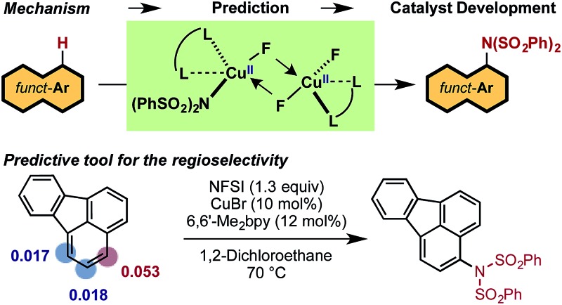
 Dinuclear CuII–CuII intermediate is an active catalyst for an unusual stepwise two-electron oxidation by NFSI, a regioselectivity predictive tool and a new catalyst development.
Abstract
The LCuBr-catalyzed C–H imidation of arenes by N-fluorobenzenesulfonimide (NFSI), previously reported by us, utilizes an inexpensive catalyst and is applicable to a broad scope of complex arenes. The computational and experimental study reported here shows that the mechanism of the reaction is comprised of two parts: (1) generation of the active dinuclear CuII–CuII catalyst; and (2) the catalytic cycle for the C–H bond imidation of arenes. Computations show that the LCuIBr complex used in experiments is not an active catalyst. Instead, upon reacting with NFSI it converts to an active dinuclear CuII–CuII catalyst that is detected using HRMS techniques. The catalytic cycle starting from the CuII–CuII dinuclear complex proceeds via (a) one-electron oxidation of the active catalyst by NFSI to generate an imidyl radical and dinuclear CuII–CuIII intermediate, (b) turnover-limiting single-electron-transfer (SET1) from the arene to the imidyl radical, (c) fast C–N bond formation with an imidyl anion and an aryl radical cation, (d) reduction of the CuII–CuIII dinuclear intermediate by the aryl radical to regenerate the active catalyst and produce an aryl-cation intermediate, and (e) deprotonation and rearomatization of the arene ring to form the imidated product. The calculated KIE for the turnover-limiting SET1 step reproduces its experimentally observed value. A simple predictive tool was developed and experimentally validated to determine the regiochemical outcome for a given substrate. We demonstrated that the pre-reaction LCuX complexes, where X = Cl, Br and I, show a similar reactivity pattern as these complexes convert to the same catalytically active dinuclear CuII–CuII species.
Introduction
There exists a need for reliable catalytic methods capable of installing nitrogen functionalities onto a broad range of precious organic substrates. Of particular interest are arylamine functionalities (i.e., aryl C–N bond formation) due to their privileged status in biomolecules1 and materials.2,3 Extensive investigations have established that conventional transition-metal-catalyzed methods (such as the Buchwald–Hartwig amination) can produce new aryl C–N bonds by coupling aryl halides with several types of amines.4–10 However, these approaches require pre-functionalization of the halide substrates. Therefore, the search for synthetic methods to directly transform C–H bonds into C–N bonds is of the utmost importance.
Indeed, the use of C–H amination11–16 methods allow for direct access to the desired C–N functionality in a vast range of hydrocarbons and are cost-effective and environmentally friendly.17–19 A pertinent example is the recent breakthrough by Nicewicz and coworkers utilizing organic photoredox catalysis to functionalize arene substrates with N-heterocycles and ammonium salts.20 Transition metal catalyzed aryl C–H amination is another highly attractive approach, but it suffers from limitations such as the need for a directing group,21–25 excess of arene substrate,26,27 and limited substrate scope.28,29
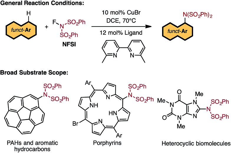
Recent studies by Baran and coworkers30 and Ritter and coworkers31,32 explicitly address these limitations by creating new C–N bonds with ferrocene and Pd catalysts, respectively, without the need of a directing group or excess aromatic substrate. Along the same lines, Cu-catalyzed aromatic C–H imidation with N-fluorobenzenesulfonimide (NFSI), reported by Itami and coworkers,33 not only utilizes an earth-abundant transition metal complex (CuBr) and a commonly available bipyridine ligand, 6,6′-dimethyl-2,2′-bipyridine (6,6′-Me2bpy), but is also applicable to a broad scope of complex arenes relevant to bio-functional and materials systems (Fig. 1). Intriguingly, the reactivity of the Cu catalyst shows a strong dependence on the 6,6′-substitution of the bpy ligand with the highest yields achieved using 6,6′-Me2bpy.33 As such, an atomistic level understanding of the mechanism of this important reaction will greatly advance the burgeoning field of aromatic C–H amination.
Fig. 1. LCuIBr-catalyzed aromatic C–H imidation with NFSI that is applicable to a broad range of functional aromatic molecules.33 .
A number of previously reported experiments provide some insight into the mechanism of this reaction.33 Namely, independent deuterium labeling studies with 2-phenylthiophene (1) and 2-deuterio-5-phenylthiophene (1-D) show an inverse kinetic isotope effect (KIE) of k H/k D = 0.91 at 70 °C,33–37 which implies addition to the arene in the rate-limiting step.33 This finding is instrumental in understanding why the electronic nature of the arene substrate is important to the observed activity of the catalyst: (a) arenes with extended π-systems and electron-rich heterocycles react nicely, but simple aromatics such as benzene produce low yields; and (b) electron-rich arenes react faster than electron-deficient arenes in competition experiments.33 It also should be noted that this reaction, as well as that reported by Ritter and coworkers,31,32 proceeds with unusually high levels of regioselectivity with a broad range of substrates. Ritter and coworkers32 attribute this to significant charge transfer from the arene to the highly electrophilic nitrogen radical derived from Selectfluor in the C–N bond-forming step. Lectka and coworkers also describe importance of the electronic effect in Cu-catalyzed C(sp3)–H fluorination with Selectfluor.38 It remains to be seen if this is also the case for the NFSI oxidant.
In general, NFSI is a two-electron oxidant that belongs to a class of electrophilic fluorinating reagents39 used as an equivalent of the highly oxidizing fluoronium cation (“F+”).40–43 For example, as shown by Muñiz, NFSI reacts with PdII as a two-electron oxidant to form a PdIV intermediate.44 However, NFSI is a versatile reagent that is known to also react in one-electron processes such as radical fluorination (F˙) of alkyl radicals.45–49 Therefore, a better understanding of how NFSI reacts with earth-abundant transition metals complexes such as the LCuBr is highly desirable.
Based on the above-mentioned findings,31–33,50–54 previously we proposed the following multi-step mechanism for the LCuIBr catalyzed aromatic C–H imidation (where L = 6,6′-Me2bpy) by NFSI (Fig. 2): (a) oxidation of LCuIBr by NFSI to form LCuIIIBrF(NSI), (I), [where NSI = N(SO2Ph)2] in equilibrium with LCuIIBrF and imidyl radical (II);54 (b) rate-limiting imidyl radical addition to the arene substrate (C–N bond formation) to form aryl radical (III); (c) single electron transfer (SET) from the aryl radical to LCuIIBrF to regenerate the LCuIBr catalyst and produce an aryl cation (IV) and coordinated F–, and (d) deprotonation and rearomatization of the aryl cation by F– to afford the imidated arene product and HF.
Fig. 2. Proposed catalytic cycle for LCuIBr-catalyzed aromatic C–H imidation with NFSI.33,54 .
However, this proposed mechanism lacks the intimate details of the reaction that are essential to rationally design more effective catalysts for selective C–H imidation and to predict the regioselective outcome. Therefore, here we set out to gain an in-depth understanding of the mechanism and governing factors of Cu-catalyzed aromatic C–H imidation by NFSI by means of a computational and experimental collaboration. This study provides insight into: (a) the versatile reactivity of NFSI; (b) the true nature of the active Cu catalyst; and (c) the impact of the nature of arene substrate on the observed reactivity and selectivity. The acquired fundamental knowledge will be used to develop the next generation of novel catalysts and ligands for selective C–H imidation with broader scope and higher reactivity.
Results and discussion
Geometry optimizations and frequency calculations of all presented structures were performed at the B3LYP-D3/[6-31G(d,p) + Lanl2dz (Cu, Br, I)] level of theory (B3LYP-D3/BS1). The reported energies were re-computed at the B3LYP-D3/[6-311+G(d,p) + SDD (Cu, Br, and I)] level of theory (B3LYP-D3/BS2). The calculated Gibbs free energies are corrected to a solution standard state of 1 M at 298.15 K.55,56 Bulk solvent effects are incorporated by using the IEF-PCM method57–59 with 1,2-dichloroethane (DCE) as the solvent.
The structures discussed in the text are labeled as (D)A-X-Y-Z, where A indicates the position of the structure on the free energy surface (e.g., A = 1, TS, etc.), the D prefix is appended when the structure is a dinuclear Cu complex, and X, Y, and Z explicitly identify the ligands directly attached to the Cu center(s). This notation clearly shows how the ligand environment of Cu changes as the reaction progresses (see Notes for details of the used computational procedure. Also, see the ESI† for Cartesian coordinates of all reported structures).
In situ generation of active catalyst
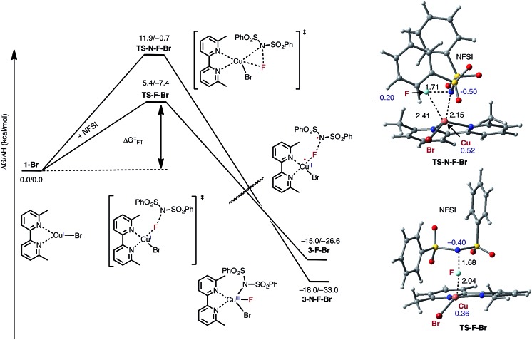
As indicated in Fig. 2, the first step of the reaction is oxidation of the LCuIBr (where L = 6,6′-Me2bpy) complex (1-Br) by NFSI (see the ESI† for analysis of full potential energy surface of the reaction). In general, this process may proceed via two distinct pathways: (a) NFSI as a two-electron oxidant,54 i.e. oxidative addition of the N–F bond to the CuI-center of LCuIBr via transition state TS-N-F-Br to form CuIII intermediate LCuIIIBrF[NSI] (3-N-F-Br) or (b) NFSI as an one-electron oxidant, i.e. one-electron oxidation of LCuIBr by F-atom transfer44,60 (at the transition state TS-F-Br) to form the CuII intermediate LCuIIBrF···[NSI], (3-F-Br) (see Fig. 3).
Fig. 3. Free energy profile for oxidation of LCuIBr through the oxidative addition (TS-N-F-Br) and F-atom transfer pathways (TS-F-Br). Bond distances (in Å) are shown in black and Mulliken spin density values (in |e|) are shown in blue. For simplicity, only the pathways through the lowest energy electronic states are shown (see the ESI† for more details).
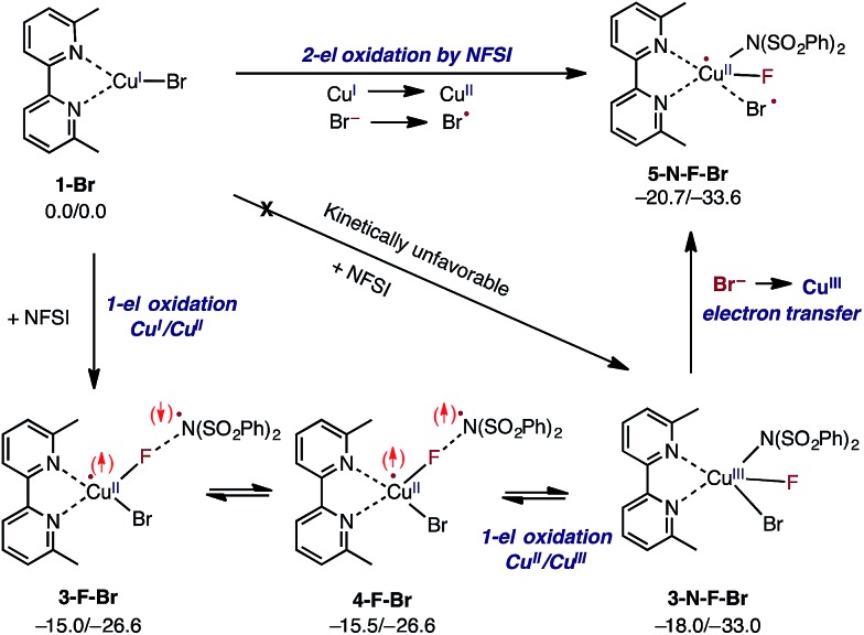
Extensive calculations show that the one-electron oxidation transition state TS-F-Br has a significant antiferromagnetic diradical character with 0.40|e| and 0.36|e| unpaired β- and α-spins on the nitrogen atom of the NSI fragment and Cu center, respectively. The free energy barrier (ΔG‡FT) associated with TS-F-Br is calculated to be 5.4 kcal mol–1 (calculated relative to 1-Br + NFSI), which is 6.5 kcal mol–1 lower than that for oxidative addition through TS-N-F-Br.61–65 Thus, based on these findings, we can conclude that the reaction of LCuIBr with NFSI proceeds through the kinetically favored one-electron oxidation pathway that leads to the formation of antiferromagnetically coupled CuII intermediate 3-F-Br (Fig. 3) with 0.71|e| and 0.67|e| unpaired β- and α-spins on the nitrogen atom of the NSI fragment and Cu center, respectively. This product is in equilibrium with its ferromagnetically-coupled counterpart 4-F-Br (see Fig. 4). The imidyl fragment of 4-F-Br has significant unpaired spin (0.74|e|) and is only weakly bound to the rest of the molecule (Cu–N = 3.51 Å).
Fig. 4. Mechanism for initial two-electron reduction of NFSI by LCuIBr (1-Br), which results in one-electron oxidation of the mono-nuclear CuI complex and a one-electron oxidation of the bromide ligand to a bromine radical. The signs of the explicitly depicted spins were assigned arbitrarily. Relative energies are given as ΔG/ΔH in kcal mol–1.
Careful analyses indicated that complex 4-F-Br easily rearranges through radical combination to the more stable two-electron oxidation product 3-N-F-Br, which is ΔG = 2.5 kcal mol–1 lower in energy (see Fig. 4). However, the CuIII complex 3-N-F-Br is also metastable and converges to the energetically most stable complex 5-N-F-Br (ΔG = –5.2 kcal mol–1 relative to 4-F-Br) with a fully formed Cu–N bond (Cu–N = 2.35 Å) and a loosely associated Br radical (Cu–Br = 2.94 Å and the Br atom has 0.75|e| unpaired spin). Thus, the 3-N-F-Br → 5-N-F-Br redox transformation entails electron transfer from the coordinated bromide ligand to the CuIII center to form a loosely associated bromine radical and a CuII center.
In summary, the presented calculations show that the reaction of LCuIBr with NFSI indeed results in a two-electron reduction of NFSI, which proceeds via (a) one-electron CuI-to-CuII oxidation through an F-atom transfer process (1-Br + NFSI → 4-F-Br) and (b) a series of one-electron redox steps leading to the formation of the most stable CuII intermediate 5-N-F-Br with a loosely coordinated Br-radical (4-F-Br → 3-N-F-Br → 5-N-F-Br). In other words, the two-electron reduction of one molecule of NFSI by LCuIBr does not result in two-electron oxidation of the Cu center but instead produces 5-N-F-Br with CuII and Br radicals (see Fig. 3 and 4). It is important to emphasize that the oxidation also does not lead to formation of the reactive imidyl radical (4-F-Br), which is endergonic by 5.2 kcal mol–1 relative to 5-N-F-Br.
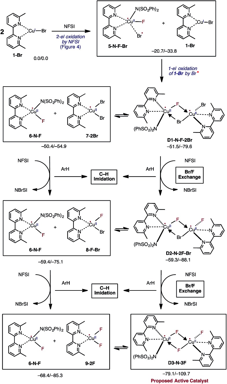
In the next step, the resulting 5-N-F-Br complex reacts with another molecule of LCuIBr (1-Br) and forms a dinuclear CuII–CuII complex D1-N-F-2Br with one terminal Br ligand and bridging F and Br ligands (Fig. 5). The formation of D1-N-F-2Br involves (a) one-electron oxidation of the second 1-Br complex by the bromine radical of 5-N-F-Br, and (b) complexation (i.e. two mono-nuclear complexes → one dinuclear complex).66 Since the reaction 5-N-F-Br + 1-Br → D1-N-F-2Br is highly exergonic (ΔG = –30.8 kcal mol–1), it is reasonable to conclude that in the reaction mixture 1-Br will be fully converted to D1-N-F-2Br by NFSI.
Fig. 5. Mechanistic steps of the reaction of two molecules of LCuIBr with three molecules of oxidant NFSI that leads to generation of the catalytically active dinuclear CuII–CuII (D3-N-3F) catalyst. This process is referred to Br/F exchange in the text. Relative energies are given as ΔG/ΔH in kcal mol–1.
Thus, the overall reaction 2 (1-Br) + NFSI → D1-N-F-2Br consists of concurrent one-electron oxidation of two distinct mononuclear CuI complexes by one NFSI molecule (Fig. 4 and 5). In the closely related literature analogs of bimetallic oxidation by one molecule of oxidant,67–70 the oxidant simultaneously oxidizes two metal centers by one-electron each. However, in the reported reaction of CuBr with NFSI, the oxidant is added to the same metal center and the auxiliary ligand (i.e., Br) is responsible for oxidation of the second metal center. Thus, the distinction between what we propose and the examples in the literature for bimetallic oxidation lies in the fate of the oxidant. Furthermore, it is important to emphasize that the newly reported mechanism of the reaction of LCuIBr with one molecule of NFSI does not produce the reactive imidyl radical and, consequently, cannot lead directly to C–N bond formation. This novel finding is profoundly different from the two-electron oxidative addition mechanism of this reaction proposed by Zhang and coworkers.54
Close examination of the dinuclear CuII–CuII complex D1-N-F-2Br shows that it is in equilibrium with two mono-nuclear CuII complexes: the disproportionation reaction D1-N-F-2Br → LCuIIF[NSI] (6-N-F) + LCuIIBr2 (7-2Br) is only slightly endergonic (ΔG = 1.1 kcal mol–1, see Fig. 5). Therefore, one may expect that both dinuclear D1-N-F-2Br and mono-nuclear 7-2Br complexes will be present in the reaction mixture and can react with another molecule of NFSI (Fig. 5).71 Surprisingly, regardless of the nuclearity of the reactant complexes, i.e. starting from either dinuclear D1-N-F-2Br or mono-nuclear 7-2Br complexes, the reaction with a second NFSI molecule leads to exchange of one Br ligand for a F ligand and concomitant formation of N-bromobenzenesulfonimide (NBrSI).
The mechanism for this process (called here Br/F exchange) is very complex: it is initiated by oxidation of the CuII species by NFSI to form CuIII and an imidyl radical. As expected, the barrier for oxidation of the CuII complexes (ΔG‡FT = 25.9 and 23.6 kcal mol–1 for the dinuclear D1-N-F-2Br and mono-nuclear 7-2Br CuII complexes, respectively) is much higher than the barrier for oxidation of the CuI complex 1-Br (ΔG‡FT = 5.4 kcal mol–1). Then, extraction of a bromine radical by the generated imidyl radical produces NBrSI and CuII, as shown in Fig. 5 (see the ESI† for more detailed discussion and free energy surface for this process).
Even though Br/F exchange from D1-N-F-2Br and 7-2Br is exergonic by 7.8 and 8.9 kcal mol–1, respectively, it is possible that a small amount of the imidyl radical will be able to escape from the Cu solvation shell to react with the substrate. However, this is not expected to lead to a high level of C–N product formation due to fast imidyl–bromine radical combination leading to NBrSI formation.
The resulting dinuclear complex D2-N-2F-Br (with only one Br ligand) and mono-nuclear complexes LCuIIF(NSI) (6-N-F) + LCuIIBrF (8-F-Br) are in equilibrium (ΔG = 0.1 kcal mol–1), and can react with a third NFSI molecule. The reaction of D2-N-2F-Br and NFSI leads to formation of the dinuclear complex [LCuIIF(NSI)···LCuIIF2] D3-N-3F, and a second molecule of NBrSI. The resulting dinuclear complex D3-N-3F has three fluoride ligands (i.e., no Br ligands) and is the energetically most stable intermediate in the series of Br/F exchange processes shown in Fig. 5. Interestingly, this dinuclear complex is stable relative to disproportionation to the mono-nuclear complexes LCuIIF(NSI) (6-N-F) + LCuIIF2 (9-2F) by ΔG = –10.7 kcal mol–1.
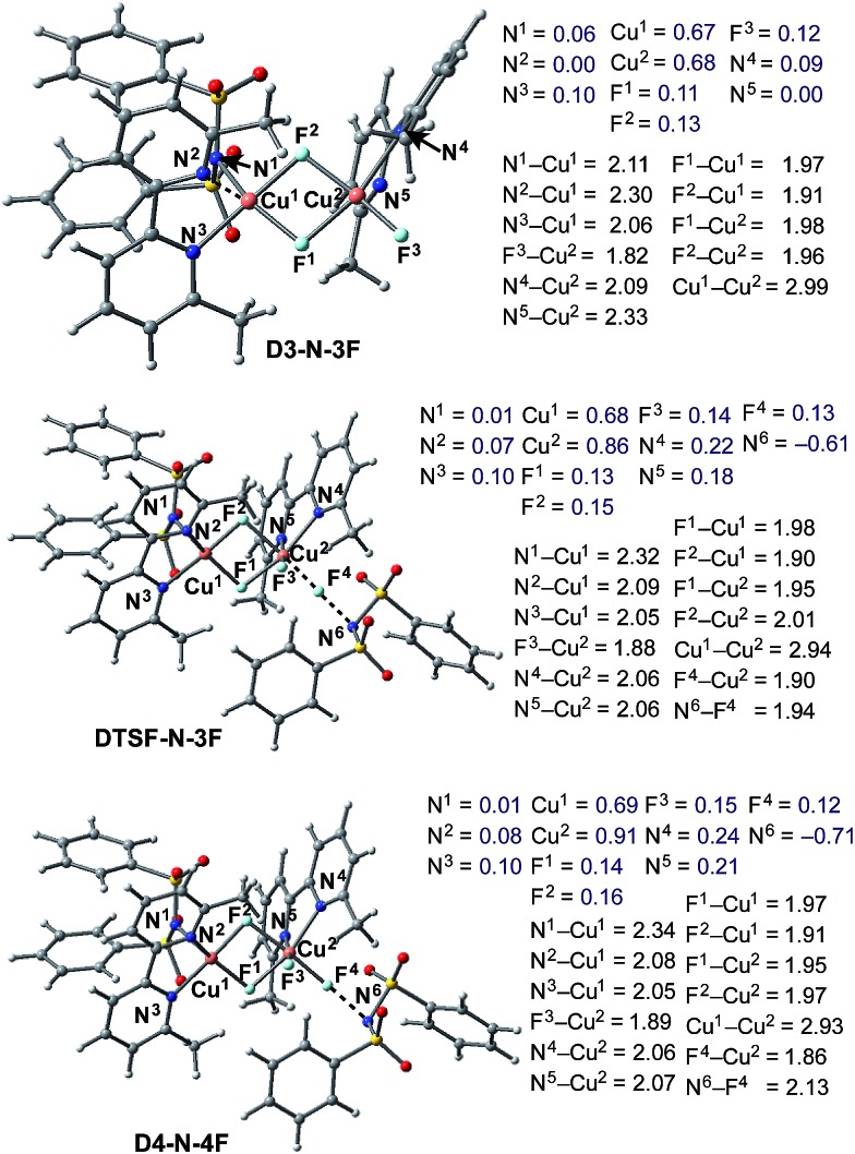
Briefly, the dinuclear complex [LCuIIF(NSI)···LCuIIF2] D3-N-3F has the characteristic diamond core with bridging fluoride ligands and two square planar CuII centers sitting in the same plane72 (Fig. 6). The diamond core of D3-N-3F closely resembles that of other dinuclear Cu2F2 complexes that have previously been extensively characterized,73–77 but their role in catalysis is under-appreciated. In D3-N-3F, both bipyridine ligands are asymmetrically bound: each CuII center has one pyridine loosely coordinated at its axial position (the calculated N2–Cu1 and N5–Cu2 bond distances are 2.30 and 2.33 Å, respectively). As shown across Fig. 3–5, the overall Br/F exchange reaction 2 1-Br + 3 NFSI → D3-N-3F + 2 NBrSI, is highly exergonic (ΔG = –79.1 kcal mol–1) and requires a maximum free energy barrier of 24.7 kcal mol–1 (see the ESI†), which is reasonable for the experimental reaction conditions. Thus, the dinuclear CuII–CuII complex D3-N-3F is the sole and thermodynamically most stable Cu species from the reaction of two molecules of CuI complex 1-Br with three molecules of NFSI oxidant involving a series of redox steps and Br/F exchange.
Fig. 6. Structural analysis of the active catalyst (D3-N-3F), antiferromagnetic F-atom transfer transition state (DTSF-N-3F) and imidyl radical product complex (D4-N-4F) involved in the oxidation of D3-N-3F by NFSI. Bond distances (in Å) are shown in black and Mulliken spin density values (in |e|) are shown in blue.
Generation of the reactive imidyl radical
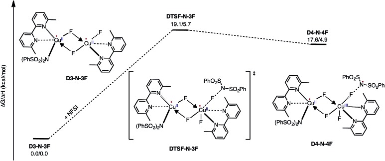
Armed with the aforementioned findings, we examined the reaction of D3-N-3F with a fourth molecule of NFSI. The barrier for this reaction, at the antiferromagnetic F-atom transfer transition state DTSF-N-3F, is found to be ΔG‡FT = 19.1 kcal mol–1 (Fig. 7).
Fig. 7. Free energy profile for oxidation of the catalytically active dinuclear CuII–CuII complex D3-N-3F by NFSI and the formation of the reactive imidyl radical complex (D4-N-4F) on the triplet surface.
As shown in Fig. 6, in the transition state, DTSF-N-3F, F4 is transferred from NFSI to Cu2 trans to the bridging fluoride ligand F2. This process triggers ligand rearrangements on the dinuclear Cu core. The imidyl group rotates to the axial position of Cu1 resulting in the N1–Cu1 bond elongates to 2.32 Å. This is likely due to rearrangement of F3 to the axial position of Cu2 in order to accommodate the incoming F4. At the same time, the bipyridine ligands on each Cu center go from the aforementioned asymmetric coordination mode to a symmetric coordination mode (N2–Cu1 2.09 Å and N5–Cu2 2.06 Å) to provide additional stabilization to the oxidized structure.
This oxidation reaction is endergonic by ΔG = 17.6 kcal mol–1 (Fig. 7), suggesting that the imidyl radical will be present in low concentrations so that the likelihood of homo-coupling or other side reactions involving imidyl radicals is reduced. In the product complex D4-N-4F, the CuIII center has an octahedral geometry. Oxidation of this Cu center is evident by an increase in its unpaired Mulliken spin from D3-N-3F (0.68|e|) to DTSF-N-3F (0.86|e|) to D4-N-4F (0.91|e|), while significant delocalization of unpaired spin is found on the ligands. In addition, the Cu–Cu distance decreases (2.99 → 2.93 Å) indicating weak coupling between the Cu centers: possibly indicating the formation of a weak two-center/one-electron (or less) Cu–Cu bond (see the ESI† for more analysis). Therefore, it is a reasonable to conclude that the dinuclear structural motif, additional fluoride ligands and bipyridine ligands together play a significant role in facilitating the oxidation process. This statement is also supported by the calculation of the barrier for oxidation of the mononuclear CuII complex 9-2F by NFSI: we found that the barrier of this reaction is ΔG‡FT = 28.4 kcal mol–1, which is 9.3 kcal mol–1 higher than oxidation of the dinuclear complex D3-N-3F by NFSI.
Therefore, in contrast to the active catalyst generation steps, NFSI reacts with the catalytically active dinuclear CuII–CuII complex, D3-N-3F, as a one-electron oxidant to generate a dinuclear CuII–CuIII intermediate and a reactive imidyl radical through a reasonable energy barrier (ΔG‡FT = 19.1 kcal mol–1). Based on the aforementioned mechanistic findings, we predict that the identity of the LCuIX pre-catalyst, where X = Cl, Br, and I, is not directly connected to the imidation reactivity, so these pre-catalysts should show similar reactivity upon loss of their X groups and in situ formation of the same active dinuclear CuII–CuII catalyst (D3-N-3F) when reacting with NFSI. [For more details of the reaction of LCuX (where X = F, Cl and I) with NFSI, see the ESI†].
Experimental validation
Thus, the computations predict that, at the initial stage of the reaction of LCuIBr with NFSI, all of the LCuIBr complexes (10 mol% under the standard conditions) converge irreversibly to the active dinuclear CuII–CuII catalyst (D3-N-3F) and NBrSI. In order to validate these computational findings, we launched extensive experimental studies.
At first, considering NBrSI as an electrophilic brominating reagent similar to N-bromosuccinimide (NBS), we suspected that its generation in situ might lead to unwanted side reactions. Indeed, we found that the reaction of 2-phenylthiophene, 1, with NFSI in the presence of LCuIBr (10 mol%) produces 5% of 2-bromo-5-phenylthiophene, 2, as a side product (Fig. 8).
Fig. 8. Detection of brominated substrate, 2, during the reaction with 2-phenylthiophene, 1.
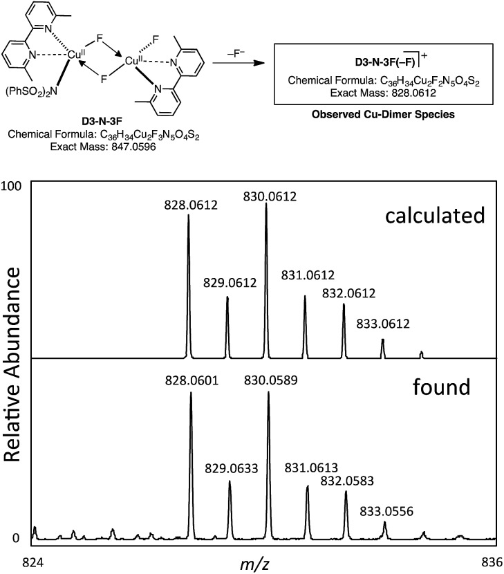
However, our extensive efforts to detect NBrSI in the reaction mixture by HRMS were not successful. Alternatively, it is also possible that an in situ generated CuBr species or Br2 can act as a brominating reagent. This result does support the computational prediction that the initial CuBr catalyst is converted to a different species through loss of its bromide ligand. As described above, the computations predict that the result of the Br/F exchange process is D3-N-3F. Gratifyingly, we were able to detect by HRMS a copper-dimer species D3-N-3F(–F), which would be generated from D3-N-3F in the same mixture (Fig. 9) (it is also possible that loss of Br from D2-N-2F-Br, but computations suggest that D3-N-3F is more likely based on thermodynamics). Thus, we experimentally confirmed the generation of D3-N-3F in the reaction system, as predicted by the computation.
Fig. 9. Observation of a copper-dimer species D3-N-3F(–F) by HRMS.
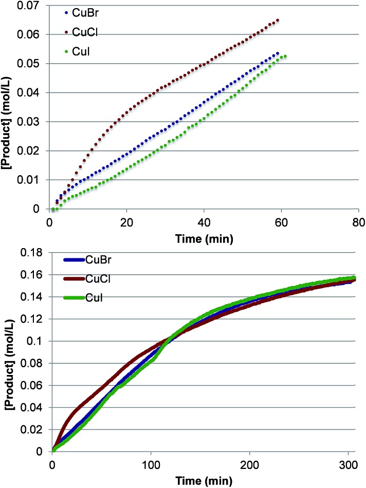
To investigate further the nature of the active catalyst and to validate the conclusions of the computations, we also performed the reaction with various LCuX complexes, where X = Cl, Br and I. Interestingly, the reaction with 1 produces similar yield of imidated product after 5 h regardless of the identity of X: 77%, 77% and 78% with CuCl, CuBr, and CuI, respectively. In addition, the kinetic profiles of the reaction with these pre-catalysts show that over the full time course each reaction converges to the same rate (Fig. 10). This suggests that each pre-catalyst of the reaction is converted to the same species, which acts as the predominant catalyst in the reaction. Together these experimental findings and the aforementioned computational data allow us to conclude reasonably that the C–H imidation activity of LCuX complexes with NFSI is catalyzed by a dinuclear CuII–CuII complex, D3-N-3F, that is generated in situ from LCuX precursors. We expect that these findings will provide insight for other reactions catalyzed by CuI-salts, and in particular, will aid in the design of more efficient and inexpensive pre-catalysts for the reaction that, for example, do not require excess NFSI or sacrifice an amount of the substrate.
Fig. 10. Kinetic profiles at short times (top) and the full time course (bottom) of product formation for pre-catalysts LCuX, where X = Cl, Br, and I.
Radical addition and generation of C–N imidation product
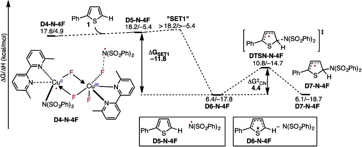
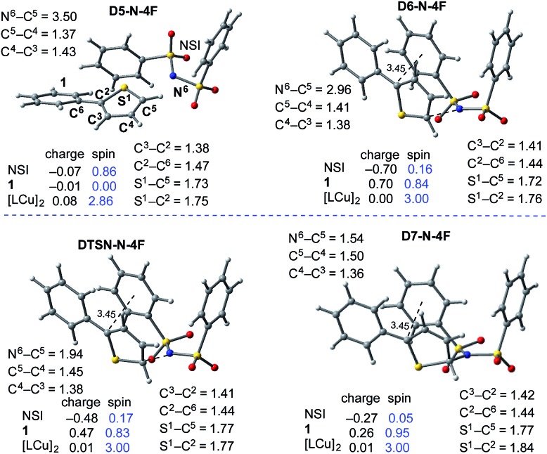
In the next step, association of the imidyl radical of D4-N-4F with the 2-phenylthiophene (1) substrate forms a weakly coordinated complex D5-N-4F. This process is almost thermoneutral (ΔG = 0.6 kcal mol–1) (Fig. 11). However, as the imidyl radical and 1 approach each other (N6–C1 = 3.50 Å → 2.96 Å, Fig. 12), single electron transfer (SET1) occurs from the π-system of 1 to the imidyl radical. This process is exergonic (ΔG SET1 = –11.8 kcal mol–1) and leads to the formation of intermediate D6-N-4F, which can be characterized as an ion-pair between an imidyl anion and aryl radical-cation. Electron transfer in this complex is evidenced by the build-up of unpaired spin (0.84|e|) and positive charge (0.70|e|) on the ring of 1 (Fig. 12). Unfortunately, we are not able to accurately compute the exact value of the free energy barrier required for SET1 with the methods used in this study. Therefore, we estimate it to be greater than the energy of the pre-reaction complex D5-N-4F, i.e. >18.2 kcal mol–1 (Fig. 11).
Fig. 11. Free energy surface for the stepwise mechanism for C–N bond formation starting with electron transfer from 1 to the imidyl radical (SET1) followed by C–N bond formation by the resulting ion-pair to produce an aryl radical intermediate. All energies are computed relative to D3-N-3F + NFSI and are calculated for the energetically lowest antiferromagnetically coupled triplet states except D7-N-4F, for which this electronic state is not stable. Therefore, for D7-N-4F we report the quintet electronic state energy, which is very close to that for the triplet state for all the other structures (see the ESI†). The dinuclear Cu complex is included in all calculations but has been removed from the Figure for clarity.
Fig. 12. Geometric and electronic structure analysis of the intermediates of C–N bond formation between the imidyl radical and 1. Bond distances (in Å) are shown in black and Mulliken spin density values (in |e|) are shown in blue. The dinuclear Cu complex has been removed from the Figure for clarity. The structures on the quintet and triplet electronic states are geometrically, electronically, and energetically similar (see the ESI†). For the antiferromagnetically-coupled triplet electronic states the spin values of the NSI and 1 fragments have the opposite sign.
From the product of the single electron transfer step (D6-N-4F), C–N bond formation occurs through an energy barrier of ΔG‡CN = 4.4 kcal mol–1 (at the transition state DTSN-N-4F) and leads to the aryl radical intermediate D7-N-4F 78 (Fig. 11). Thus, C–N bond formation (i.e., the reaction of D4-N-4F with 1) occurs through a stepwise mechanism involving (i) single electron transfer (SET1) from the π-system of 1 to the imidyl radical of D4-N-4F, and (ii) C–N bond formation at the transition state DTSN-N-4F.
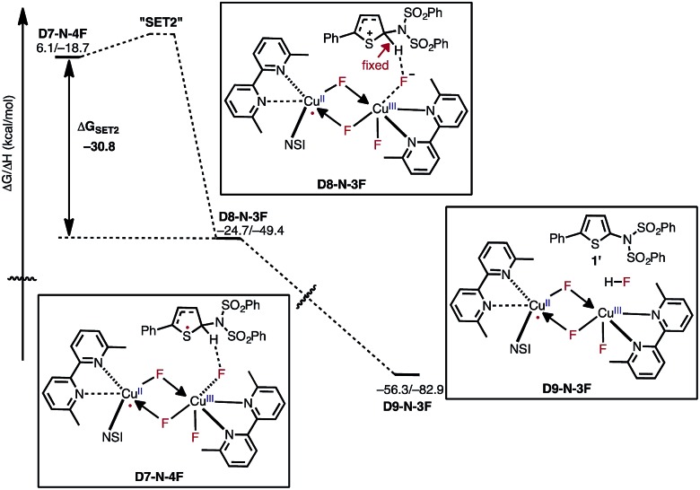
After the aryl radical is formed, the next step of the reaction is another single electron transfer (SET2) from the aryl radical to the dinuclear CuII–CuIII complex (Fig. 13). This step should produce an aryl cation and dinuclear CuII–CuII complex with a coordinated fluoride anion (D8-N-3F). However, all our attempts to locate this structure resulted in the deprotonation product D9-N-3F. To estimate the thermodynamic stability of D8-N-3F, we optimized the structure by fixing the C–H bond distance to 1.09 Å, and found that SET2 is thermodynamically favored by ΔG = –30.2 kcal mol–1. The fact that D8-N-3F could not be located without geometry constraint indicates that subsequent deprotonation and rearomatization of the substrate by fluoride anion is barrierless (see the ESI† for energy scans). The formation of the product, HF, and the active catalyst (D3-N-3F) in complex D9-N-3F is highly exergonic from D8-N-3F (ΔG = –31.6 kcal mol–1). Indeed, the overall reaction, D3-N-3F + NFSI + 1 → D3-N-3F + 1′ + HF is calculated to be ΔG = –62.8 kcal mol–1 exergonic.
Fig. 13. Free energy surface for active catalyst regeneration and product formation, which proceeds through an electron transfer to the catalyst and ejection of fluoride anion. The fluoride anion then deprotonates and rearomatizes the aryl cation intermediate to generate the imidated product and HF. The presented energies are computed relative to the D3-N-3F + NFSI dissociation limit.
Careful analysis of the energy span79 (δE) for the entire free energy surface of the reaction of D3-N-3F with NFSI and 1 substrate indicates that its turnover-determining intermediate (TDI) is D3-N-3F + NFSI + 1. However, based only on the presented energy calculations, it is not straightforward to determine the turnover-limiting TS (TDTS) of the reaction because we were not able to compute accurately the energy barrier associated with the SET1 step (i.e., electron transfer from the substrate to the imidyl radical), the actual mechanism of which depends on many factors including (but not limited to) the nature of solvent and driving force for electron transfer. Furthermore, its estimated value of >18.2 kcal mol–1 is very close to the 19.1 kcal mol–1 energy barrier calculated for oxidation of D3-N-3F by NFSI. Since these two barriers are shown to be the largest energy barriers on the full potential energy surface of the reaction, we expect either oxidation of D3-N-3F by NFSI or SET1 to be the turnover-limiting step of overall reaction.
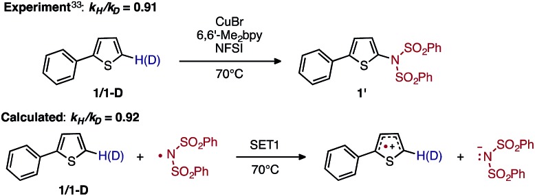
To discriminate between these possible turnover-limiting steps, we examined the H/D substrate kinetic isotope effect (KIE). The oxidation step (i.e., D3-N-3F → DTSF-N-3F → D4-N-4F) does not involve the substrate, so if it is the turnover-limiting step, there should not be any substrate KIE. In contrast, the calculated isotope effect for the SET1 step (i.e., D5-N-4F → D6-N-4F), which is found to be k H/k D = 0.92 at 70 °C, (calculated from the 5-hydrogen and 5-deuterium isotopologues of 1, see the ESI† for more details) is in excellent agreement with the previously determined experimental33 KIE of k H/k D = 0.91 at 70 °C as shown in Fig. 14.
Fig. 14. Schematic presentation of the experimental33 and computational isotope effect studies for electron transfer from 1 to the imidyl radical.
Based on the calculated and measured KIEs, we conclude that the SET1 step is the turnover-limiting step of the reaction. The calculated KIE can be attributed to differences in the zero point energies of harmonic frequencies arising from delocalization of the adjacent sulfur lone pair into the anti-bonding orbital (n–σ*) of the C–H and C–D bonds.80–83 Although measured inverse KIEs often are attributed to the change in C(sp)2 → C(sp)3 hybridization in the TS,34–37 previous studies have also shown that electron transfer reactions can produce inverse isotope effects.84,85
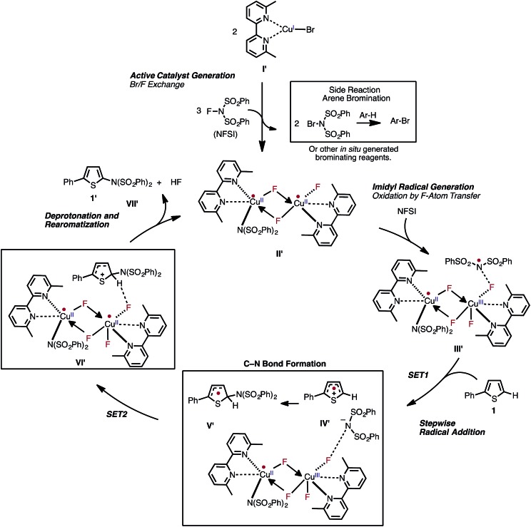
Based on the aforementioned computational and experimental findings, we propose a novel dinuclear mechanism for the LCuIBr-catalyzed aromatic C–H imidation with NFSI that includes the following steps (Fig. 15): (1) conversion of the LCuIBr pre-catalyst (I) through a series of Br/F exchange reactions with NFSI to the active dinuclear CuII–CuII catalyst (II′); (2) oxidation of the active catalyst by NFSI via one-electron F-atom transfer pathway that generates a reactive imidyl radical (III′); (3) stepwise C–N bond formation comprising of turnover-limiting single-electron-transfer (SET1) from the substrate to the imidyl radical produces an ion-pair (IV′), and subsequently fast C–N bond coupling to form an aryl radical (V′); (4) reduction of the dinuclear CuII–CuIII intermediate by the aryl radical that produces an aryl cation, fluoride anion; and (5) deprotonation and rearomatization of the arene ring by the fluoride anion to form the imidated product and HF (VII′) and regeneration of the active catalyst (II′).
Fig. 15. The newly proposed mechanism for Cu-catalyzed aromatic C–H imidation by NFSI based on the collaborative computational and experimental results described in this study. The novel reaction mechanism has two major parts: (1) generation of the dinuclear CuII–CuII active catalyst; and (2) subsequent catalytic cycle for aromatic C–H imidation with NFSI.
The above-presented mechanism for the LCuIBr-catalyzed C–H imidation with NFSI provides an opportunity to examine the effect of the substrate on the reaction, to improve the efficiency of the catalysis, and to widen substrate scope.
Substrate effect
A major strength of this reaction is its applicability to a wide range of arene substrates. However, to further expand its activity to entirely new substrates requires better understanding of the factors impacting the reactivity of a given substrate. Based on the computed mechanism above, we hypothesized that the reactivity of a given substrate will depend on its ability to induce electron transfer. It is natural to expect that electron-rich substrates will most easily be oxidized by the imidyl radical. To further probe this hypothesis, we computationally investigate the mechanism of the reaction for benzene, which experimentally produces lower yields than 2-phenylthiophene.33
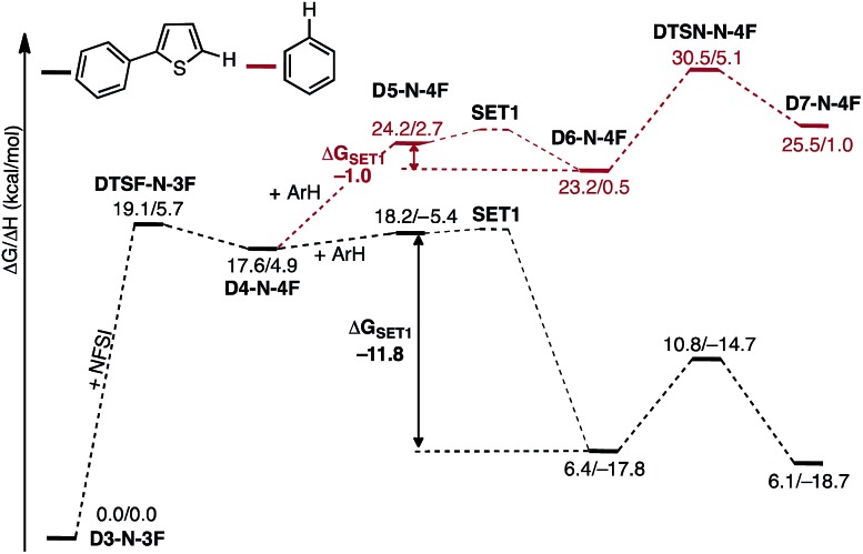
As shown in Fig. 16, the SET1 (i.e., D5-N-4F → D6-N-4F) step for benzene (ΔG SET1 = –1.0 kcal mol–1) is energetically much less favorable than for 2-phenylthiophene (ΔG SET1 = –11.8 kcal mol–1). In addition, oxidation of benzene is dramatically more endergonic than 2-phenylthiophene, calculated relative to the D3-N-3F + substrate. As a result, the SET1 step and the subsequent C–N bond formation transition state are pushed much higher in energy with benzene. This outcome is consistent with the experimental observation that excess benzene is required to generate low yields of product.33 This finding also explains why electron-rich arenes react faster than electron-deficient arenes in competition experiments.33
Fig. 16. Free energy surfaces for stepwise C–N bond formation with 2-phenylthiophene (black) and benzene (red).
Factors impacting the regioselectivity of the reaction
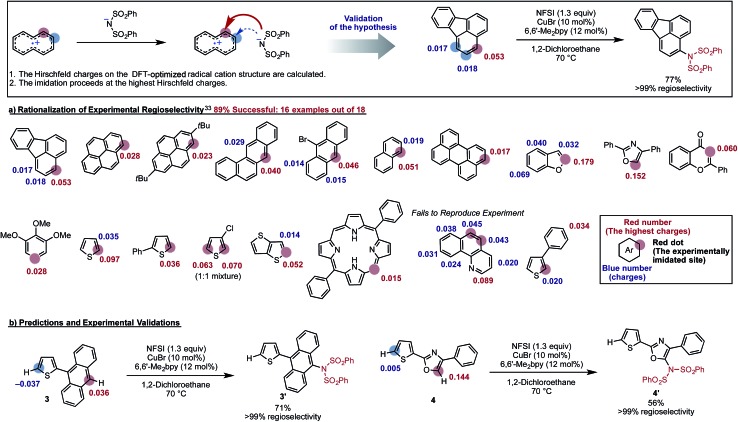
The proposed new mechanism of the Cu-catalyzed aromatic C–H imidation by NFSI is also consistent with the experimentally observed high-levels of regioselectivity of the reaction. Since the turnover-limiting step (D3-N-3F → SET1) of the reaction is indiscriminate toward the regioselectivity, it is reasonable to expect that the relative barriers for C–N bond formation at each position will dictate the regioselectivity (i.e., C–N bond formation is the regioselectivity-determining step). Therefore, we hypothesized that the positive charge on the arene carbons bearing hydrogen atoms in the oxidized substrate (i.e., radical cation) will be predictive for the regiochemical outcome of the reaction. To validate this hypothesis, we calculated the Hirshfeld charges86 of the radical cation for a number of substrates used in the experiment.33 This approach is similar to the “charge-transfer-directed” concept of Ritter and coworkers.31,32
We find excellent agreement between the proposed charge model and the experimentally observed regioselectivity in most cases (Fig. 17). To show the utility of this simple predictive tool, we predicted that imidation of 3 and 4 would occur on the anthracene and oxazole rings of these substrates, respectively. These predictions were then confirmed by experiments showing that the predicted imidated products were formed with >99% regioselectivity (Fig. 17).
Fig. 17. Validation of a model to predict the site of C–H imidation based on the calculated Hirshfeld charges (shown in red and blue) on the DFT-optimized radical cation structure of each substrate. The experimentally imidated site is indicated by a red sphere and the site with the highest positive charge is indicated with red numbers. Other possible sites for imidation are indicated with blue spheres. Using this model, regioselectivity predictions were made for new substrates, 3 and 4. The predictions for these substrates were then validated experimentally producing the predicted product with >99% selectivity.
Close examination of the substrates where the regioselectivity predictions fail (see Fig. 17) also gives useful insight into the limitations of our predictive model, such as: (a) the assumption that the deprotonation and rearomatization step of the reaction is faster than SET1;87 and (b) not including the role of external directing effects such as hydrogen bonds, π-stacking, steric hindrance or other non-covalent interactions. However, we expect that the user can easily anticipate these limitations of the model and generate an acceptably accurate prediction of the site of imidation in a given molecule quickly and reliably (see the ESI† for the detailed procedure of this simple predictive tool).
Conclusions
Above, we utilized a joint computational and experimental collaboration to obtain an in-depth understanding of the mechanism and governing factors of Cu-catalyzed aromatic C–H imidation with NFSI and propose a novel dinuclear mechanism (see Fig. 15) for this reaction. Briefly,
(1) We found that prior to initiation of the catalytic cycle NFSI acts like a two-electron oxidant by reacting with two molecules of LCuIBr and producing the dinuclear CuII–CuII complex [LCuIIF(NSI)···LCuIIBr2], D3-N-F-2Br. The predicted bimetallic oxidation reaction with one molecule of oxidant is unprecedented because here NFSI directly interacts only with one equivalent of LCuIBr resulting in simultaneous one-electron oxidation of both the CuI center and Br-ligand, which then oxidizes the second molecule of LCuIBr.
(2) In contrast, in the next stage of the reaction NFSI acts as overall redox neutral molecule: two molecules of NFSI react with the dinuclear CuII–CuII complex D3-N-F-2Br via the Br/F exchange pathway and produce two molecules of NBrSI (or other Br-containing molecules) and the catalytically active dinuclear CuII–CuII complex [LCuIIF(NSI)···LCuIIF2], D3-N-3F. The resulting dinuclear CuII–CuII complex is predicted to be the thermodynamically most stable Cu species of the reaction. Subsequent HRMS experiments detected a copper-dimer species D3-N-3F(–F) and confirmed the generation of the dinuclear CuII–CuII complex D3-N-3F in the reaction system, as predicted by computation.
(3) Since the dinuclear CuII–CuII complex [LCuIIF(NSI)···LCuIIF2], D3-N-3F, is shown to be the catalytically active species, we predicted that the identity of the LCuIX pre-catalyst, where X = Cl, Br, and I, is not directly connected to its imidation activity. This prediction of computation also was validated by experiments by showing that (a) the reaction with 2-phenylthiophene produces a similar yield regardless of the identity of X, and (b) over the full time course the kinetic profile of the reaction with LCuIX converges to the same rate.
(4) The catalytic cycle starts from the reaction of the dinuclear CuII–CuII complex D3-N-3F with NFSI, as a one-electron oxidant, and forms the reactive imidyl radical and the CuII–CuIII dinuclear intermediate. This reaction subsequently proceeds through the following elementary steps: (a) stepwise C–N bond formation between the substrate and imidyl radical proceeding via turnover-limiting single-electron-transfer (SET1) from the substrate to the imidyl radical followed by fast imidyl anion and aryl radical-cation coupling to produce an aryl radical intermediate; (b) reduction of the CuII–CuIII dinuclear intermediate by the resulting aryl radical to regenerate the active catalyst and produce an aryl cation and fluoride anion; and (c) deprotonation and rearomatization of the arene ring by the fluoride anion to form the imidated product and HF.
(5) The utilization of these mechanistic findings revealed that the limited reactivity of benzene should be attributed to its lower ability to be oxidized by the imidyl radical in the turnover-limiting SET1 step. We predicted that electron-rich substrates will be relatively easily oxidized by the imidyl radical and, consequently, will be more reactive toward C–H imidation, which is consistent with our previously reported experiments.33
(6) We developed a simple computational tool for predicting the regioselectivity for imidation and demonstrated that C–N bond formation is the regioselectivity-determining step. Subsequent experiments confirmed our computational predictions and validated the predictive power of this simple regioselectivity tool.
In summary, the atomistic-level understanding gained from our joint computational and experimental studies, presented here for the Cu-catalyzed aromatic C–H imidation by NFSI, will not only be instrumental for the development of the next generation of novel catalysts and ligands for selective aromatic C–H imidation, but also open many prospects for the design of novel, efficient, and highly selective reactions with earth-abundant transition metal catalysts and other nitrogen radical sources.
Experimental
Computational and experimental procedures
Computational methodology
Geometry optimizations and frequency calculations of all presented structures were performed with the Gaussian-09 suite of programs88 at the B3LYP-D3/[6-31G(d,p) + Lanl2dz (Cu, Br, I)] level of theory (below, termed as B3LYP-D3/BS1) with the corresponding Hay–Wadt effective core potentials for Cu, Br and I89–91 and Grimme's empirical dispersion-correction for B3LYP.92 The frequency analysis is used to characterize each minimum with zero imaginary frequencies and transition state (TS) structures with only one imaginary frequency. Intrinsic reaction coordinate (IRC) calculations were performed for selected TSs to ensure their true nature and to connect proper reactants and products. The calculated Gibbs free energies are corrected to a solution standard state of 1 M at 298.15 K.55,56 Bulk solvent effects are incorporated for all calculations (i.e. geometry optimization, frequency, and single point energy calculations) using the self-consistent reaction field polarizable continuum model (IEF-PCM)57–59 with 1,2-dichloroethane (DCE) as the solvent. The electronic energies were re-computed at the B3LYP-D3/[6-311+G(d,p) + SDD (Cu, Br, and I)] level of theory (below, termed as B3LYP-D3/BS2) with the corresponding effective core potentials for Cu, Br and I.93–95 The thermal corrections for the free energy and enthalpy are calculated at the B3LYP-D3/BS1 level. These corrections were then applied to the energies calculated at the B3LYP-D3/BS2 level to afford the reported free energy and enthalpy values. Because of the clear importance of entropy on the reaction profiles, we focus the discussion on the free energies in the text.
The electronic states of each transition state and intermediate were carefully analyzed. It was found that many of the TSs and intermediates on the singlet potential energy surface have lower energy open-shell singlet electronic states. In these cases, we re-calculated the geometries and energies of the structures at their open-shell singlet electronic states using unrestricted DFT (UB3LYP-D3).96,97 The presented Hirshfeld charges98–100 were computed at the B3LYP-D3/BS2 level of theory.
Experimental methodology
Unless otherwise noted, all reactants or reagents including dry solvents were obtained from commercial suppliers and used as received. CuBr was purchased from Nacalai Tesque, Inc. NFSI and 6,6′-Me2bpy were purchased from TCI. Anhydrous 1,2-dichloroethane was purchased from Kanto Chemical Co., Inc. All reactions were performed with dry solvents under an atmosphere of N2 gas in flame-dried glassware using standard vacuum-line techniques. All work-up and purification procedures were carried out with reagent-grade solvents in air. For kinetic experiments using in situ IR, the reaction spectra were recorded using an IC 15 from Mettler-Toledo AutoChem. Data processing was carried out using Microsoft® Excel® for Mac v. 14.2.5.
Experimental procedures are as follows: a three-necked reaction vessel equipped with a magnetic stirring bar was dried with a heat gun. CuX, where X = Cl, Br and I, (0.060 mmol, 10 mol%), 6,6′-Me2bpy (13 mg, 0.072 mmol, 12 mol%), NFSI (199 mg, 0.63 mmol, 1.05 equiv.), and triphenylene (69 mg, 0.3 mmol; an internal standard for 1H NMR analysis) were added to the vessel. The IR probe was inserted through an adapter into the middle neck; another neck was capped by a rubber septum for the purpose of reagent injection, and the third was jointed with a three-way cock in order to flow N2 gas. This vessel was evacuated and purged with N2 three times. DCE (2 mL) was then added to the vessel and the mixture was heated at 70 °C in an oil bath. After stirring the mixture for 6 min, 1 (0.6 M, DCE solution, 1 mL) was added to the vessel via a syringe and at this point the data collection was started. In situ IR spectra were recorded over the course of the reaction.
Experimental procedures for imidation of 2-(9-anthryl)-thiophene (3) and 4-phenyl-2-(thiophen-2-yl)oxazole (4) are as follows: to a Schlenk tube were added NFSI (66 mg, 0.21 mmol, 1.05 equiv.), CuBr (2.8 mg, 0.020 mmol, 10 mol%) and 6,6′-Me2bpy (4.4 mg, 0.024 mmol, 12 mol%) in open air. The tube was filled with N2 by employing a usual Schlenk evacuate–refill cycle technique. DCE (1.0 mL) and the starting material (0.20 mmol) were added to the tube and the mixture was heated at 70 °C for 12 h. The mixture was then cooled to 25 °C. The crude solution was filtered through a pad of silica gel and Na2SO4 and concentrated in vacuo. Purification by chromatography on silica gel (hexane/EtOAc = 5 : 1) provided the corresponding imidated product (3′, 79.3 mg, 0.14 mmol, 71%; 4′, 58.8 mg, 0.11 mmol, 56%).
Acknowledgments
This work was supported by the National Science Foundation under the CCI Center for Selective C–H Functionalization (CHE-1205646 for D. G. M.), the ERATO program from JST (K. I.), a Grant-in-Aid from JSPS (15K17821 to K. M.), and the Takeda Pharmaceutical Company Award in Synthetic Organic Chemistry, Japan (K. M.). The authors gratefully acknowledge NSF MRI-R2 grant (CHE-0958205 for D. G. M.) and the use of the resources of the Cherry Emerson Center for Scientific Computation. The authors acknowledge members of the CCI Center for Selective C–H Functionalization for fruitful discussions. ITbM is supported by the World Premier International Research Center (WPI) Initiative, Japan.
Footnotes
References
- Uno S. N., Kamiya M., Yoshihara T., Sugawara K., Okabe K., Tarhan M. C., Fujita H., Funatsu T., Okada Y., Tobita S., Urano Y. Nat. Chem. 2014;6:681–689. doi: 10.1038/nchem.2002. [DOI] [PubMed] [Google Scholar]
- Li L. L., Diau E. W. G. Chem. Soc. Rev. 2013;42:291–304. doi: 10.1039/c2cs35257e. [DOI] [PubMed] [Google Scholar]
- Shirota Y., Kageyama H. Chem. Rev. 2007;107:953–1010. doi: 10.1021/cr050143+. [DOI] [PubMed] [Google Scholar]
- Fukui N., Cha W. Y., Lee S., Tokuji S., Kim D., Yorimitsu H., Osuka A. Angew. Chem., Int. Ed. 2013;52:9728–9732. doi: 10.1002/anie.201304794. [DOI] [PubMed] [Google Scholar]
- Hartwig J. F. Acc. Chem. Res. 2008;41:1534–1544. doi: 10.1021/ar800098p. [DOI] [PMC free article] [PubMed] [Google Scholar]
- Ley S. V., Thomas A. W. Angew. Chem., Int. Ed. 2003;42:5400–5449. doi: 10.1002/anie.200300594. [DOI] [PubMed] [Google Scholar]
- Ma D. W., Cai Q. A. Acc. Chem. Res. 2008;41:1450–1460. doi: 10.1021/ar8000298. [DOI] [PubMed] [Google Scholar]
- Surry D. S., Buchwald S. L. Angew. Chem., Int. Ed. 2008;47:6338–6361. doi: 10.1002/anie.200800497. [DOI] [PMC free article] [PubMed] [Google Scholar]
- Surry D. S., Buchwald S. L. Chem. Sci. 2010;1:13–31. doi: 10.1039/C0SC00107D. [DOI] [PMC free article] [PubMed] [Google Scholar]
- Valente C., Calimsiz S., Hoi K. H., Mallik D., Sayah M., Organ M. G. Angew. Chem., Int. Ed. 2012;51:3314–3332. doi: 10.1002/anie.201106131. [DOI] [PubMed] [Google Scholar]
- Jiao J., Murakami K., Itami K. ACS Catal. 2016;6:610–633. [Google Scholar]
- Shin K., Kim H., Chang S. Acc. Chem. Res. 2015;48:1040–1052. doi: 10.1021/acs.accounts.5b00020. [DOI] [PubMed] [Google Scholar]
- Lyons T. W., Sanford M. S. Chem. Rev. 2010;110:1147–1169. doi: 10.1021/cr900184e. [DOI] [PMC free article] [PubMed] [Google Scholar]
- Kaliappan K. P., Subramanian P., Rudolf G. C. Chem.–Asian J. 2016;11:168–192. doi: 10.1002/asia.201500361. [DOI] [PubMed] [Google Scholar]
- Thansandote P., Lautens M. Chem.–Eur. J. 2009;15:5874–5883. doi: 10.1002/chem.200900281. [DOI] [PubMed] [Google Scholar]
- Dong X., Liu Q., Dong Y., Liu H. Chem.–Eur. J. 2016 doi: 10.1002/chem.201601607. [DOI] [Google Scholar]
- Segawa Y., Maekawa T., Itami K. Angew. Chem., Int. Ed. 2015;54:66–81. doi: 10.1002/anie.201403729. [DOI] [PubMed] [Google Scholar]
- Wencel-Delord J., Glorius F. Nat. Chem. 2013;5:369–375. doi: 10.1038/nchem.1607. [DOI] [PubMed] [Google Scholar]
- Yamaguchi J., Yamaguchi A. D., Itami K. Angew. Chem., Int. Ed. 2012;51:8960–9009. doi: 10.1002/anie.201201666. [DOI] [PubMed] [Google Scholar]
- Romero N. A., Margrey K. A., Tay N. E., Nicewicz D. A. Science. 2015;349:1326–1330. doi: 10.1126/science.aac9895. [DOI] [PubMed] [Google Scholar]
- Shang M., Sun S. Z., Dai H. X., Yu J. Q. J. Am. Chem. Soc. 2014;136:3354–3357. doi: 10.1021/ja412880r. [DOI] [PubMed] [Google Scholar]
- Yoo E. J., Ma S., Mei T. S., Chan K. S. L., Yu J. Q. J. Am. Chem. Soc. 2011;133:7652–7655. doi: 10.1021/ja202563w. [DOI] [PubMed] [Google Scholar]
- Kim H., Chang S. ACS Catal. 2016:2341–2351. doi: 10.1021/acscatal.6b00293. [DOI] [Google Scholar]
- Roane J., Daugulis O. J. Am. Chem. Soc. 2016;138:4601–4607. doi: 10.1021/jacs.6b01117. [DOI] [PMC free article] [PubMed] [Google Scholar]
- Raghuvanshi K., Zell D., Rauch K., Ackermann L. ACS Catal. 2016;6:3172–3175. [Google Scholar]
- Allen L. J., Cabrera P. J., Lee M., Sanford M. S. J. Am. Chem. Soc. 2014;136:5607–5610. doi: 10.1021/ja501906x. [DOI] [PMC free article] [PubMed] [Google Scholar]
- Antonchick A. P., Samanta R., Kulikov K., Lategahn J. Angew. Chem., Int. Ed. 2011;50:8605–8608. doi: 10.1002/anie.201102984. [DOI] [PubMed] [Google Scholar]
- Kawano T., Hirano K., Satoh T., Miura M. J. Am. Chem. Soc. 2010;132:6900–6901. doi: 10.1021/ja101939r. [DOI] [PubMed] [Google Scholar]
- Wang Q., Schreiber S. L. Org. Lett. 2009;11:5178–5180. doi: 10.1021/ol902079g. [DOI] [PMC free article] [PubMed] [Google Scholar]
- Foo K., Sella E., Thome I., Eastgate M. D., Baran P. S. J. Am. Chem. Soc. 2014;136:5279–5282. doi: 10.1021/ja501879c. [DOI] [PMC free article] [PubMed] [Google Scholar]
- Boursalian G. B., Ham W. S., Mazzotti A. R., Ritter T. Nat. Chem. 2016;8:810–815. doi: 10.1038/nchem.2529. [DOI] [PMC free article] [PubMed] [Google Scholar]
- Boursalian G. B., Ngai M. Y., Hojczyk K. N., Ritter T. J. Am. Chem. Soc. 2013;135:13278–13281. doi: 10.1021/ja4064926. [DOI] [PMC free article] [PubMed] [Google Scholar]
- Kawakami T., Murakami K., Itami K. J. Am. Chem. Soc. 2015;137:2460–2463. doi: 10.1021/ja5130012. [DOI] [PubMed] [Google Scholar]
- Do Amaral L., Bull H. G., Cordes E. H. J. Am. Chem. Soc. 1972;94:7579–7580. [Google Scholar]
- Nakane R., Kurihara O., Takematsu A. J. Org. Chem. 1971;36:2753–2756. [Google Scholar]
- Olah G. A. Acc. Chem. Res. 1971;4:240–248. [Google Scholar]
- Olah G. A., Kuhn S. J., Flood S. H. J. Am. Chem. Soc. 1961;83:4571–4580. [Google Scholar]
- Pitts C. R., Bloom S., Woltornist R., Auvenshine D. J., Ryzhkov L. R., Siegler M. A., Lectka T. J. Am. Chem. Soc. 2014;136:9780–9791. doi: 10.1021/ja505136j. [DOI] [PubMed] [Google Scholar]
- Lal G. S., Pez G. P., Syvret R. G. Chem. Rev. 1996;96:1737–1755. doi: 10.1021/cr941145p. [DOI] [PubMed] [Google Scholar]
- Engle K. M., Mei T. S., Wang X. S., Yu J. Q. Angew. Chem., Int. Ed. 2011;50:1478–1491. doi: 10.1002/anie.201005142. [DOI] [PMC free article] [PubMed] [Google Scholar]
- Liang T., Neumann C. N., Ritter T. Angew. Chem., Int. Ed. 2013;52:8214–8264. doi: 10.1002/anie.201206566. [DOI] [PubMed] [Google Scholar]
- Bobbio C., Gouverneur V. Org. Biomol. Chem. 2006;4:2065–2075. doi: 10.1039/b603163c. [DOI] [PubMed] [Google Scholar]
- Champagne P. A., Desroches J., Hamel J. D., Vandamme M., Paquin J. F. Chem. Rev. 2015;115:9073–9174. doi: 10.1021/cr500706a. [DOI] [PubMed] [Google Scholar]
- Iglesias A., Alvarez R., de Lera A. R., Muñiz K. Angew. Chem., Int. Ed. 2012;51:2225–2228. doi: 10.1002/anie.201108351. [DOI] [PubMed] [Google Scholar]
- Halperin S. D., Fan H., Chang S., Martin R. E., Britton R. Angew. Chem., Int. Ed. 2014;53:4690–4693. doi: 10.1002/anie.201400420. [DOI] [PubMed] [Google Scholar]
- Halperin S. D., Kwon D., Holmes M., Regalado E. L., Campeau L. C., DiRocco D. A., Brittont R. Org. Lett. 2015;17:5200–5203. doi: 10.1021/acs.orglett.5b02532. [DOI] [PubMed] [Google Scholar]
- Nodwell M. B., Bagai A., Halperin S. D., Martin R. E., Knust H., Britton R. Chem. Commun. 2015;51:11783–11786. doi: 10.1039/c5cc04058b. [DOI] [PubMed] [Google Scholar]
- Rueda-Becerril M., Sazepin C. C., Leung J. C. T., Okbinoglu T., Kennepohl P., Paquin J. F., Sammis G. M. J. Am. Chem. Soc. 2012;134:4026–4029. doi: 10.1021/ja211679v. [DOI] [PubMed] [Google Scholar]
- West J. G., Bedell T. A., Sorensen E. J. Angew. Chem., Int. Ed. 2016;55:8923–8927. doi: 10.1002/anie.201603149. [DOI] [PMC free article] [PubMed] [Google Scholar]
- Kaneko K., Yoshino T., Matsunaga S., Kanai M. Org. Lett. 2013;15:2502–2505. doi: 10.1021/ol4009848. [DOI] [PubMed] [Google Scholar]
- Ni Z. K., Zhang Q., Xiong T., Zheng Y. Y., Li Y., Zhang H. W., Zhang J. P., Liu Q. Angew. Chem., Int. Ed. 2012;51:1244–1247. doi: 10.1002/anie.201107427. [DOI] [PubMed] [Google Scholar]
- Zhang B., Studer A. Org. Lett. 2014;16:1790–1793. doi: 10.1021/ol500513b. [DOI] [PubMed] [Google Scholar]
- Zhang H. W., Pu W. Y., Xiong T., Li Y., Zhou X., Sun K., Liu Q., Zhang Q. Angew. Chem., Int. Ed. 2013;52:2529–2533. doi: 10.1002/anie.201209142. [DOI] [PubMed] [Google Scholar]
- Zhang H. W., Song Y. C., Zhao J. B., Zhang J. P., Zhang Q. Angew. Chem., Int. Ed. 2014;53:11079–11083. doi: 10.1002/anie.201406797. [DOI] [PubMed] [Google Scholar]
- Essafi S., Tomasi S., Aggarwal V. K., Harvey J. N. J. Org. Chem. 2014;79:12148–12158. doi: 10.1021/jo502020e. [DOI] [PubMed] [Google Scholar]
- Plata R. E., Singleton D. A. J. Am. Chem. Soc. 2015;137:3811–3826. doi: 10.1021/ja5111392. [DOI] [PMC free article] [PubMed] [Google Scholar]
- Cances E., Mennucci B., Tomasi J. J. Chem. Phys. 1997;107:3032–3041. [Google Scholar]
- Mennucci B., Tomasi J. J. Chem. Phys. 1997;106:5151–5158. [Google Scholar]
- Scalmani G., Frisch M. J. J. Chem. Phys. 2010;132:114110–114124. doi: 10.1063/1.3359469. [DOI] [PubMed] [Google Scholar]
- Liu Q. L., Yuan Z. L., Wang H. Y., Li Y., Wu Y. C., Xu T., Leng X. B., Chen P. H., Guo Y. L., Lin Z. Y., Liu G. S. ACS Catal. 2015;5:6732–6737. [Google Scholar]
- Jones G. O., Liu P., Houk K. N., Buchwald S. L. J. Am. Chem. Soc. 2010;132:6205–6213. doi: 10.1021/ja100739h. [DOI] [PMC free article] [PubMed] [Google Scholar]
- Yu H. Z., Jiang Y. Y., Fu Y., Liu L. J. Am. Chem. Soc. 2010;132:18078–18091. doi: 10.1021/ja104264v. [DOI] [PubMed] [Google Scholar]
- Lefevre G., Franc G., Tlili A., Adamo C., Taillefer M., Ciofini I., Jutand A. Organometallics. 2012;31:7694–7707. [Google Scholar]
- Zhang S. L., Bie W. F., Huang L. Organometallics. 2014;33:5263–5271. [Google Scholar]
- Zhang S. L., Fan H. J. Organometallics. 2013;32:4944–4951. [Google Scholar]
- The study of the exact mechanism of this process, which could occur via stepwise (complexation-then-oxidation) or concerted pathways, is beyond scope of this paper
- Breitenfeld J., Ruiz J., Wodrich M. D., Hu X. L. J. Am. Chem. Soc. 2013;135:12004–12012. doi: 10.1021/ja4051923. [DOI] [PubMed] [Google Scholar]
- Powers D. C., Benitez D., Tkatchouk E., Goddard W. A., Ritter T. J. Am. Chem. Soc. 2010;132:14092–14103. doi: 10.1021/ja1036644. [DOI] [PMC free article] [PubMed] [Google Scholar]
- Schley N. D., Fu G. C. J. Am. Chem. Soc. 2014;136:16588–16593. doi: 10.1021/ja508718m. [DOI] [PMC free article] [PubMed] [Google Scholar]
- Zhu D., Budzelaar P. H. M. Organometallics. 2010;29:5759–5761. [Google Scholar]
- Dissociation of the imidyl radical from 6-N-F, i.e., LCuIIF[NSI] → LCuIF + ˙NSI, is calculated to be unfavorable by ΔG = 39.9 kcal mol–1. This indicates that the formation of a reactive imidyl radical from 6-N-F is unlikely
- Rodriguez-Fortea A., Alemany P., Alvarez S., Ruiz E. Inorg. Chem. 2002;41:3769–3778. doi: 10.1021/ic011308+. [DOI] [PubMed] [Google Scholar]
- Hefni M. A., Mcconnell N. M., Rietmeijer F. J., Gribnau M. C. M., Keijzers C. P. Mol. Phys. 1986;57:1283–1296. [Google Scholar]
- Jacobson R. R., Tyeklar Z., Karlin K. D., Zubieta J. Inorg. Chem. 1991;30:2035–2040. [Google Scholar]
- Lee S. C., Holm R. H. Inorg. Chem. 1993;32:4745–4753. [Google Scholar]
- Marino N., Armentano D., De Munno G., Cano J., Lloret F., Julve M. Inorg. Chem. 2012;51:4323–4334. doi: 10.1021/ic202740b. [DOI] [PubMed] [Google Scholar]
- Rietmeijer F. J., Degraaff R. A. G., Reedijk J. Inorg. Chem. 1984;23:151–156. [Google Scholar]
- D7-N-4F is unstable toward SET2 on the triplet surface. For the C–N bond forming process, the energies of the triplet and quintet states are very close in energy (see the ESI). Therefore, we expect that the calculations of D7-N-4F on the quintet surface will be an adequate approximation of the same structure on the triplet surface
- Kozuch S., Shaik S. Acc. Chem. Res. 2011;44:101–110. doi: 10.1021/ar1000956. [DOI] [PubMed] [Google Scholar]
- Halevi E. A. New J. Chem. 2014;38:3840–3852. [Google Scholar]
- Halevi E. A. New J. Chem. 2015;39:1522–1524. [Google Scholar]
- Perrin C. L. New J. Chem. 2015;39:1517–1521. [Google Scholar]
- Perrin C. L., Flach A. Angew. Chem., Int. Ed. 2011;50:7674–7676. doi: 10.1002/anie.201102125. [DOI] [PubMed] [Google Scholar]
- Fiksel A. I., Parmon V. N., Zamaraev K. I. Chem. Phys. 1982;69:135–139. [Google Scholar]
- Ulstrup J., Jortner J. J. Chem. Phys. 1975;63:4358–4368. [Google Scholar]
- Recently Hirshfeld charges have been successful used in predicting regioselectivity in electrophilic aromatic substitution reactions. See: Liu S. B., J. Phys. Chem. A, 2015, 119 , 3107 –3111 . [DOI] [PubMed] [Google Scholar]
- This might be the case for benzo[h]quinolone, where imidation is observed on the middle ring at the positions bearing the second highest amount of positive charge in the calculations. This can be explained by the higher resonance energy of benzene relative to pyridine. See: Fishtik I., Grimme S., Phys. Chem. Chem. Phys., 2012, 14 , 15888 –15896 .23093113 [Google Scholar]
- Frisch M. J., Trucks G. W., Schlegel H. B., Scuseria G. E., Robb M. A., Cheeseman J. R., Scalmani G., Barone V., Mennucci B., Petersson G. A., Nakatsuji H., Caricato M., Li X., Hratchian H. P., Izmaylov A. F., Bloino J., Zheng G., Sonnenberg J. L., Hada M., Ehara M., Toyota K., Fukuda R., Hasegawa J., Ishida M., Nakajima T., Honda Y., Kitao O., Nakai H., Vreven T., Montgomery Jr J. A., Peralta J. E., Ogliaro F., Bearpark M., Heyd J. J., Brothers E., Kudin K. N., Staroverov V. N., Kobayashi R., Normand J., Raghavachari K., Rendell A., Burant J. C., Iyengar S. S., Tomasi J., Cossi M., Rega N., Millam M. J., Klene M., Knox J. E., Cross J. B., Bakken V., Adamo C., Jaramillo J., Gomperts R., Stratmann R. E., Yazyev O., Austin A. J., Cammi R., Pomelli C., Ochterski J. W., Martin R. L., Morokuma K., Zakrzewski V. G., Voth G. A., Salvador P., Dannenberg J. J., Dapprich S., Daniels A. D., Farkas Ö., Foresman J. B., Ortiz J. V., Cioslowski J. and Fox D. J., Gaussian 09, Revision D.01, Gaussian, Inc., Wallingford CT, 2009.
- Hay P. J., Wadt W. R. J. Chem. Phys. 1985;82:270–283. [Google Scholar]
- Hay P. J., Wadt W. R. J. Chem. Phys. 1985;82:299–310. [Google Scholar]
- Wadt W. R., Hay P. J. J. Chem. Phys. 1985;82:284–298. [Google Scholar]
- Grimme S., Antony J., Ehrlich S., Krieg H. J. Chem. Phys. 2010;132:154104–154119. doi: 10.1063/1.3382344. [DOI] [PubMed] [Google Scholar]
- Andrae D., Haussermann U., Dolg M., Stoll H., Preuss H. Theor. Chim. Acta. 1990;77:123–141. [Google Scholar]
- Igelmann G., Stoll H., Preuss H. Mol. Phys. 1988;65:1321–1328. [Google Scholar]
- Vonszentpaly L., Fuentealba P., Preuss H., Stoll H. Chem. Phys. Lett. 1982;93:555–559. [Google Scholar]
- Marell D. J., Furan L. R., Woods B. P., Lei X., Bendelsmith A. J., Cramer C. J., Hoye T. R., Kuwata K. T. J. Org. Chem. 2015;80:11744–11754. doi: 10.1021/acs.joc.5b01356. [DOI] [PMC free article] [PubMed] [Google Scholar]
- Zou L. F., Paton R. S., Eschenmoser A., Newhouse T. R., Baran P. S., Houk K. N. J. Org. Chem. 2013;78:4037–4048. doi: 10.1021/jo400350v. [DOI] [PMC free article] [PubMed] [Google Scholar]
- Hirshfeld F. L. Theor. Chim. Acta. 1977;44:129–138. [Google Scholar]
- Ritchie J. P. J. Am. Chem. Soc. 1985;107:1829–1837. [Google Scholar]
- Ritchie J. P., Bachrach S. M. J. Comput. Chem. 1987;8:499–509. [Google Scholar]
Associated Data
This section collects any data citations, data availability statements, or supplementary materials included in this article.


