Abstract
Traveling-wave MRI, which uses relatively small and simple RF antennae, has robust matching performance and capability for large field-of-view (FOV) imaging. However, the power efficiency of traveling-wave MRI is much lower than conventional methods, which limits its application. One simple approach to improve the power efficiency is to place passive resonators around the subject being imaged. The feasibility of this approach has been demonstrated in previous works using a single small resonant loop. In this work, we aim to explore how much the improvements can be maintained in human imaging using an array design, and whether electric dipoles can be used as local elements. First, a series of electromagnetic (EM) simulations were performed on a human model. Then RF coils were constructed and the simulation results using the best setup for head imaging were validated in MR experiments. By using the passive local loop and transverse dipole arrays, respectively, the transmit efficiency (B1+) of traveling-wave MRI can be improved by 3-fold in the brain and 2-fold in the knee. The types of passive elements (loops or dipoles) should be carefully chosen for brain or knee imaging to maximize the improvement, and the enhancement depends on the local body configuration.
Keywords: Magnetic Resonance Imaging, ultraghigh field, traveling-wave, transmit efficiency, passive, inductive coupling
2. Introduction
Traveling-wave MRI, which was proposed by Brunner et al [1], is a promising technique for imaging large samples using relatively small, easy-to-build antennae, rather than conventional, large body coils whose design is technically challenging at high fields [2-4]. In traveling-wave MRI, the transmit/receive antenna can be positioned relatively far away (>50 cm) from the imaged subject, which improves patient comfort and leaves more space for other hardware such as local receive arrays and non-proton RF coils [5,6]. It also has robust tuning and matching performance because the imaged subject is positioned in the far-field region rather than the near-field.
However, traveling-wave MR suffers from low power efficiency and sensitivity compared to traditional RF coil approaches [7]. The low efficiency of traveling-wave MR signal reception can be reduced using separate receive-only arrays [8,9], but the low transmit efficiency remains a central disadvantage of the technique. One way to improve the transmit efficiency is to deliver traveling-wave power directly to the target imaging region with a coaxial waveguide [10]. Another method is to introduce additional materials into the magnet bore, such as metamaterials [11] and dielectric fillings with specific geometry and permittivity [12,13]. An alternative simple method proposed recently is to place local resonators around the subject [14-16]. The local resonators are tuned to the proton Larmor frequency and have no connections to the MR scanner, so we refer to them as passive elements in this study. The feasibility of this approach has been demonstrated in previous work using a single small loop [14-16], where traveling-wave efficiency was improved by at least 10-fold.
Despite these previous reports, it is not clear whether other kinds of coils such as electric dipoles can be used as local elements, nor is it clear that how much the improvements can be maintained in human imaging using an array design. In this study, we investigated the possibility of using electric dipoles as the passive elements. Then, different setups were examined in electromagnetic (EM) simulations for human brain and knee imaging. Finally, the simulation results using the best setup for head imaging were validated in MR experiments.
3. Materials and Methods
3.1 Concept
In traveling-wave MRI, the scanner bore (diameter ∼60 cm) forms a cylindrical waveguide and the antenna couples through a propagating waveguide mode to the imaged sample. At 7T, only the TE11 mode has a cut-off frequency below the Larmor frequency (∼300 MHz), so the RF power of other modes attenuates rapidly with distance. In the TE11 mode, the electric (E-) field and magnetic (H-) field are both perpendicular to the direction of propagation (z-direction) at the center of the bore. When a loop is placed near the center of the bore and oriented along the z-axis (Fig 1), it inductively couples to the excitation source (the traveling-wave antenna) through the TE11 mode. Since the loop has a high quality (Q-) value and a small dimension, it couples most of the RF power that threads through it and concentrates the RF power deposition in its nearby area. In this way, the loop locally enhances B1.
Figure 1.
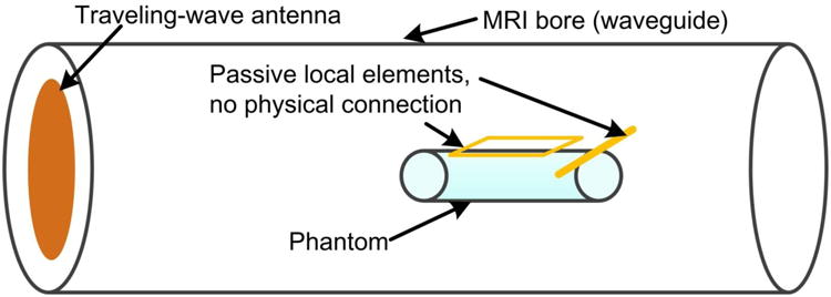
Sketch of a traveling-wave MRI system with passive local elements (loop or dipole). The passive elements are tuned to the proton Larmor frequency and have no connection to the MR scanner.
In contrast to loops, electric dipoles are open circuits and do not have current return paths, so no passive current arises from pure inductive coupling. A longitudinally-oriented dipole (the conventional orientation) [17] produces a rotary H-field in transverse planes and a z-directed E-field. It therefore does not couple to the TE11 mode because its fields are orthogonal to those of the TE11 mode. However, if the dipole is positioned in the transverse plane, its E- and H-fields are oriented transversely in front of it and behind it. Therefore the transverse dipole is expected to couple to the TE11 mode in these regions.
3.2 EM simulations
To explore whether electric dipoles can locally enhance the B1 field, traveling-wave MRI (linearly polarized) was simulated in an empty bore of a MR scanner with either a longitudinal or transverse local dipole. Simulated B1+ maps without a dipole, with a longitudinal dipole and with a transverse dipole are shown in Fig. 2A, 2B and 2C, respectively. As expected, the longitudinal dipole has no influence on the original B1+ field (Fig. 2B vs Fig. 2A), but the transverse dipole acts as a reflector and enhances B1+ strength in front of it, while reducing B1+ behind it (Fig. 2C vs Fig. 2A).
Figure 2.
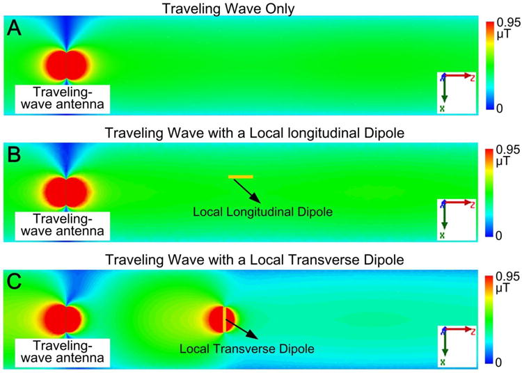
Simulated B1+ maps without local coils (A), with a local longitudinal dipole (B) and with a local transverse dipole (C). The longitudinal dipole had no influence on the original B1+ field, but the transverse dipole increased B1+ strength in front of it. This is because only the transverse dipole couples to the propagating waveguide mode (TE11), and acts as a reflector.
Four passive array setups were then examined in human body simulations: (I) brain with an 8-channel passive loop array (“head first” configuration, Fig. 3A); (II) knee with an 8-channel passive loop array (“feet first” configuration, Fig. 3B); (III) brain with a 4-channel transverse dipole array (“head first” configuration, Fig. 3C); (IV) knee with a 4-channel transverse dipole array (“feet first” configuration, Fig. 3D). Traditional traveling-wave setups without passive elements were also simulated as comparisons. The human body model consists of 300+ objects (bones, muscles, and organs) and 33 tissue types, and also has accuracies down to 1 millimeter (Fig. 3).
Figure 3.
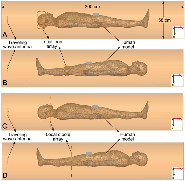
A. Simulation model of traveling-wave MRI with an 8-channel passive loop array surrounding the brain area. B: Traveling-wave with an 8-channel passive loop array surrounding the knee. C: Traveling-wave with a 4-channel transverse dipole array surrounding the head. D: Traveling-wave with a 4-channel transverse dipole array surrounding the knee. In all simulations, the traveling-wave antenna was driven with 2 Watts in CP mode.
In the simulation, the waveguide was formed by a cylindrical copper shield (inner diameter 58 cm and length 300 cm). The corresponding cut-off frequency of this waveguide is ∼303 MHz for the TE11 mode, but it can be reduced well below the Larmor frequency of 298 MHz when the human body is positioned in the waveguide. The entire simulated system was surrounded by a perfectly absorbing boundary which was placed >20 cm away from the edge of the bore. A pair of crossed dipoles segmented by inductors were placed at one end of the bore as the traveling-wave antenna. The loop array comprised eight circular loops with diameters 14.7 cm (head) and 8.2 cm (knee). Neighboring elements of the loop arrays were overlapped to minimize mutual coupling. In the dipole array, four transverse dipoles (30 cm long and 1 cm wide) were placed head-to-head. The dipole arrays were placed behind the region of interest (brain or knee), unlike the loop arrays which surrounded them.
All capacitor and inductor values of the traveling-wave antenna and the passive elements were obtained using the EM field and RF circuit co-simulation method [18]. For the traveling-wave antenna used for excitation, the values were obtained by minimizing the reflection coefficients (S11) of the excitation ports. For the passive elements (loops or dipoles), a pair of pick-up probes were used to ensure that their resonant frequencies were tuned to 298 MHz (7T proton Larmor frequency). The pick-up probes were used only to determine the lumped element values and were removed in the final simulation.
The transmission (B1+) fields were extracted from the simulation as: [19]. In all human body simulations, the traveling-wave antenna was driven with a total input power of 2 Watts in circularly polarized (CP) mode. EM simulations and RF circuit optimizations were performed with HFSS and Designer (Ansys, Canonsburg, PA, USA).
3.3 Experimental Validation
Fig. 4A shows the constructed crossed dipoles (one horizontal and one vertical) which were used as the traveling-wave antenna. Fig. 4B shows a schematic of the horizontal dipole. The dipoles were mounted on the front and back of an acrylic board (dimensions 35 × 35 cm2, thickness 6.35 mm). Each was made of 7.5-mm-wide copper tape with 30 cm length. Four inductors (two near the feed port, referred to as Lcenter) were used to shorten the length of the half-wavelength electric dipole to 30 cm. The inductance of Lcenter and the capacitance of Cm were adjusted for fine tuning and matching. Both dipoles were well matched to 50 Ω with S11 better than -25 dB, and well decoupled from each other with S21 better than -15 dB (intrinsically decoupled). A shielded cable-trap was used for each dipole to avoid common-mode currents. During MR experiments, the traveling-wave antenna was used for both transmission and reception. The crossed dipoles were connected to the MR scanner through a quadrature transmit/receive interface box.
Figure 4.
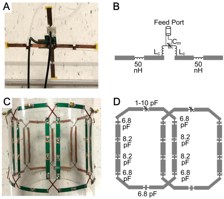
Photographs (A,C) and schematics (B,D) of the crossed dipoles (A,B) which were used as the traveling-wave antenna, and the 8-channel overlapped loop array (C,D) which was used as the passive local coil.
Fig. 4C shows the constructed 8-channel overlapped loop array which was used as the passive element. Fig. 4D depicts the diagram of two neighboring loops. The eight-channel array was mounted on a cylindrical acrylic former with an outer diameter of 25 cm. Each loop (dimensions 18 × 11.6 cm2) has nine distributed capacitors (6.8 pF and 8.2 pF, Series 1111C, Passive Plus, Huntington Station, NY) and one trimmer capacitor (1-10 pF, 52H02, Johanson Manufacturing corp., NJ, USA). As described before, the loop array is totally passive and has no excitation port, so it does not need any RF cables, matching circuits or cable-traps. Tuning and decoupling performances of the passive loop array were achieved by adjusting the trimmer capacitors and the overlapped area.
MR experiments were then performed on a 7T whole-body scanner (Philips Healthcare, Best, Netherlands) to confirm the brain loop results. Sagittal B1+ maps were acquired on a head phantom using the traveling-wave antenna with and without the passive local loop array. B1+ maps were measured using the DREAM method [20] and gradient-recalled echo (GRE) images were acquired with the same input power in both configurations. The parameters of the GRE sequence were: FOV= 20 × 20 cm2, spatial resolution 2 × 2 × 5 mm3, TR/TE= 1000/2.7 ms. The parameters of the DREAM sequence were: FOV= 20 × 20 cm2, spatial resolution 2.8 × 2.8 × 10 mm3, TR/TE= 1000/4.5 ms. The head phantom was placed at the center of the bore and the traveling-wave antenna was placed 60 cm away from the phantom. A large torso phantom (40 × 35 × 20 cm3) was placed behind the head phantom, to mimic an actual body and act as a high dielectric load that further pulled the cut-off frequency below the Larmor frequency.
4. Results
4.1 Simulation Results
Fig. 5 shows the simulated brain B1+ maps. The passive loop array increased the average B1+ field strength in the brain by a factor of 3 (0.42 μT vs. 0.14 μT), where the brain is outlined by a dark dashed line. In the traveling-wave only case, the shoulders caused large reflections due to the abrupt change of waveguide impedance. The reflected EM waves then interfered with the input waves, which led to a pronounced longitudinal standing wave profile and low transmit efficiency. With local loop arrays, this reflection was avoided since most of the power was deposited in the loops and the brain prior to arriving at the shoulders. This is also evidenced by the B1+ profile in Fig. 5B which is dominated by the local loops. The passive dipole array, however, has approximately the same B1+ profile as that of traveling-wave alone. This can be understood because the longitudinal standing wave effect dominates in the “head first” traveling-wave configuration, and thus the dipole array has little impact on the B1+ profile.
Figure 5.
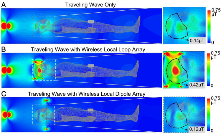
Simulated B1+ maps of traveling-wave MRI in the brain without any local coils (A), with a passive loop array (B) and with a passive transverse dipole array (C). Using the local loop array, the average B1+ amplitude increased approximately 3-fold. The local dipole array, however, had little effect and the average B1+ was actually decreased compared to traveling-wave alone.
Fig. 6 shows simulated knee B1+ maps. The local loop array increased the average B1+ field strength in the knee by a factor of 1.5 (0.20 μT vs. 0.13 μT), where the knee is outlined by the dark dashed line. In the “feet first” traveling-wave configuration, transmit power must travel across conductive tissues such as the feet and calves prior to reaching the knees. Therefore, the improvement is lower compared to the brain since much of the power is already deposited prior to reaching the knees. In comparison, the local dipole array increased the average B1+ field strength 2-fold (0.26 μT vs. 0.13 μT), which is the opposite result comparing to brain imaging. Unlike the human head and shoulders, where the waveguide impedances change abruptly, the legs constitute a gradually increasing dielectric loading and are approximately ideal for traveling-wave propagation. Thus the local dipole array provides obvious B1+ improvements in front of it, as expected from the simulation result using a single transverse dipole (Fig. 2C vs 2A).
Figure 6.
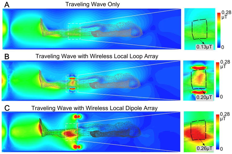
Simulated B1+ maps of traveling-wave MRI in the knee without any local coils (A), with a passive loop array (B) and with a passive transverse dipole array (C). The local loop and dipole arrays increased average B1+ about 50% and 100%, respectively.
Fig. 7 shows the traveling-wave experimental results on a head phantom with and without the 8-channel loop array. Average B1+ efficiency increased approximately 2.8-fold (58 degrees vs 21 degrees) using the local loop array, which is consistent with simulations. The measured B1 patterns also have a similar shape to the simulation results in Figs. 5A and 5B. Due to the reflection by the torso phantom (which played the role of the shoulders), the B1+ field of traveling-wave alone has a pronounced longitudinal standing wave profile, with an obvious dark band. In contrast, the B1+ field with the loop array has a pattern similar to that of a CP mode volume coil. The overall signal enhancement with the passive loops was ∼8-fold, part of which was contributed by the improved receive efficiency.
Figure 7.
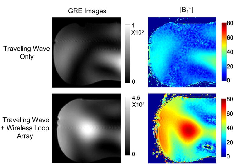
Traveling-wave MRI experimental results on a head-shaped phantom without (top row) and with (bottom row) an 8-channel passive loop array. Each loop of the passive coil array had dimensions 18 × 11.6 cm2. Similar to the simulation results, the B1+ efficiency was improved by ∼3-fold by using the passive local loop array.
5. Discussion and Conclusion
The B1+ field strength of traveling-wave MRI was improved 3-fold in the brain using a passive local loop array, which is much less than the previously-reported case of using a single small passive loop on a small phantom (>10-fold) [14,15]. This is partly because the bigger loops excited a much larger volume, and also because the passive current is shared by all the loops in the array, which improves the field homogeneity at the expense of local H′.
We also compared the B1+ map of the traveling-wave+passive loop setup to that of a directly controlled birdcage transmit coil (Nova Medical Inc., Wilmington, MA) (results not shown). With the same input power, the B1+ field using the traveling-wave+passive loops has a similar pattern but slightly lower magnitude compared to the birdcage coil. This is partly because some of the traveling-wave power dissipates in the free space or unwanted areas, and partly because the H-field near the surface of the MR bore is along the z-direction and thus does not maximally contribute to the passive current in the local loops.
One advantage of traveling-wave MRI is the robust tuning and matching performance, which is desirable for repeatable operations and short setup times at high fields. This feature could be maintained when passive elements are inserted in the MR bore. Another advantage of traveling-wave MRI is the separation of the transmit coil from the patient, which increases the space available for receive arrays and other experimental hardware, and could improve patient comfort. This benefit is maintained with the passive dipole arrays, as they are placed close to the bore and beyond the imaging area. This benefit is however somehow compromised with the passive loop arrays, though they may still improve patient comfort and workflow since they do not require the use of RF cables and cable-traps.
A standard 7T MR bore supports only TE11 mode propagates due to the stringent cut-off frequency requirement. At higher static magnetic fields [21,22] or when the bore is filled with high dielectrics [23], other waveguide modes can propagate. Although the concept of using traveling-wave+passive elements was demonstrated only for TE11 mode, it could also work for other propagating waveguide modes such as TM01 and TE21. Local loops should couple to most waveguide modes so long as they produce transverse magnetic fields. The orientation of local dipoles must be more carefully chosen to ensure coupling to the propagating mode. For example, to couple to the TM01 mode a dipole should be positioned longitudinally rather than transversely.
As mentioned above, most of the transmit efficiency improvement could be attributed to the inductive coupling (loop) and reflection effect (dipole) of the passive elements. It is also noted the ratio between B1+ and B1- in CP mode increases locally (white box in supporting Figure S1) when loaded with specific passive elements, which might also contribute to transmit efficiency improvement. The E- field increases as well when loaded with the passive local elements, as shown in previous work [15]. But it is also found that the ratio between E-field and B1+ field (E / B1+) decreases in the phantom. So for the same B1+, lower local specific absorption rate (SAR) is generated with passive elements. Similar to phantom results, the SAR efficiencies (B1+/√SAR) in human models using the passive elements are comparable to or better than those using the traveling-wave alone setup across different cases. In the “head first” case, the B1+ field using either the traveling-wave alone setup or the traveling-wave+passive elements is non-uniform in the brain area. In the “feet first” case, the traveling-wave alone setup has relatively uniform B1+ over the lower legs (including the feet, calves and knees). Passive elements (loops or dipoles) increase the B1+ field locally, so they maintain similar B1+ uniformity over the knees (the targeted area) but decrease B1+ uniformity over the rest of the lower legs. It should be noted that passive elements also provide additional freedoms to manipulate the B1+ patterns and SAR. In this work, passive elements were designed mainly for high transmit efficiency and they were tuned exactly to the Larmor frequency to achieve maximum coupling to the TE11 mode. We believe the B1+ uniformity and the SAR efficiency could be further improved by optimizing the electric and physical parameters of the passive loops/dipoles, such as the resonant frequency, capacitor/inductor distribution, geometry and distance from the subject.
In conclusion, by using passive local loop coil and transverse dipole arrays, the transmit efficiency (B1+) of traveling-wave MRI was improved by 3-fold in the brain and 2-fold in the knee in this specific study. The coil types (loops or dipoles) should be carefully chosen for each imaging target to maximize the improvement as they exhibit different types of coupling to the TE11 mode, and the enhancement depends on the local body configuration.
Supplementary Material
Highlights.
We explored the improvements of using passive loop and dipole arrays in traveling-wave MRI (7T). The improvements were validated by both electromagnetic (EM) simulations and MR experiments.
By using the passive local loop arrays and transverse dipole arrays, respectively, the transmit efficiency (B1+) of traveling-wave MRI can be improved by 3-fold in the brain and 2-fold in the knee.
In this study, we first proposed that transverse electric dipoles can be used as passive local elements.
Acknowledgments
This work was supported by NIH R01 EB 016695, NIH R21 EB 018521 and NIH R21 EB 020283.
Footnotes
Publisher's Disclaimer: This is a PDF file of an unedited manuscript that has been accepted for publication. As a service to our customers we are providing this early version of the manuscript. The manuscript will undergo copyediting, typesetting, and review of the resulting proof before it is published in its final citable form. Please note that during the production process errors may be discovered which could affect the content, and all legal disclaimers that apply to the journal pertain.
References
- 1.Brunner DO, De Zanche N, Frohlich J, Paska J, Pruessmann KP. Travelling-wave nuclear magnetic resonance. Nature. 2009;457(7232):994–998. doi: 10.1038/nature07752. [DOI] [PubMed] [Google Scholar]
- 2.Zhang B, Wiggins GC, Duan Q, Lattanzi R. Sodickson DK Whole-Body Traveling-Wave Imaging at 7T: Simulation and Early In-Vivo Experiment. Proceedings of the 17th Annual Meeting of ISMRM; Honolulu, Hawaii, USA. 2009. p. 498. [Google Scholar]
- 3.Webb AG, Collins CM, Versluis MJ, Kan HE, Smith NB. MRI and localized proton spectroscopy in human leg muscle at 7 Tesla using longitudinal traveling waves. Magn Reson Med. 2010;63(2):297–302. doi: 10.1002/mrm.22262. [DOI] [PMC free article] [PubMed] [Google Scholar]
- 4.Pang Y, Vigneron DB, Zhang X. Parallel traveling-wave MRI: a feasibility study. Magn Reson Med. 2012;67(4):965–978. doi: 10.1002/mrm.23073. [DOI] [PMC free article] [PubMed] [Google Scholar]
- 5.Mirkes CC, Hoffmann J, Shajan G, Pohmann R, Scheffler K. High-resolution quantitative sodium imaging at 9.4 Tesla. Magn Reson Med. 2015;73(1):342–351. doi: 10.1002/mrm.25096. [DOI] [PubMed] [Google Scholar]
- 6.Schmidt R, Webb A. Characterization of an HEM-Mode Dielectric Resonator for 7-T Human Phosphorous Magnetic Resonance Imaging. IEEE Trans Biomed Eng. 2016;63(11):2390–2395. doi: 10.1109/TBME.2016.2533659. [DOI] [PubMed] [Google Scholar]
- 7.Zhang B, Sodickson DK, Lattanzi R, Duan Q, Stoeckel B, Wiggins GC. Whole body traveling wave magnetic resonance imaging at high field strength: homogeneity, efficiency, and energy deposition as compared with traditional excitation mechanisms. Magn Reson Med. 2012;67(4):1183–1193. doi: 10.1002/mrm.23107. [DOI] [PMC free article] [PubMed] [Google Scholar]
- 8.Kroeze H, van de Bank BL, F V, Lagendijk JJ, Luijten P, Klomp DW, et al. Carotid Imaging at 7 Tesla Using Traveling Wave Excitation and Local Receiver Coils. Proceedings of the 17th Annual Meeting of ISMRM; Honolulu, Hawaii, USA. 2009. p. 1320. [Google Scholar]
- 9.Herrmann T, Mallow J, Plaumann M, Luchtmann M, Stadler J, Mylius J, et al. The Travelling-Wave Primate System: A New Solution for Magnetic Resonance Imaging of Macaque Monkeys at 7 Tesla Ultra-High Field. PLoS One. 2015;10(6):e0129371. doi: 10.1371/journal.pone.0129371. [DOI] [PMC free article] [PubMed] [Google Scholar]
- 10.Andreychenko A, Kroeze H, Klomp DW, Lagendijk JJ, Luijten PR, van den Berg CA. Coaxial waveguide for travelling wave MRI at ultrahigh fields. Magn Reson Med. 2013;70(3):875–884. doi: 10.1002/mrm.24496. [DOI] [PubMed] [Google Scholar]
- 11.Zivkovic I, Scheffler K. Proc Intl Soc Mag Reson Med. Milan, Italy: 2014. Metamaterial cell for B1+ field manipulation at 9.4T MRI; p. 4834. [Google Scholar]
- 12.Andreychenko A, Bluemink JJ, Raaijmakers AJ, Lagendijk JJ, Luijten PR, van den Berg CA. Improved RF performance of travelling wave MR with a high permittivity dielectric lining of the bore. Magn Reson Med. 2013;70(3):885–894. doi: 10.1002/mrm.24512. [DOI] [PubMed] [Google Scholar]
- 13.Schmidt R. Intl Soc Mag Reson Med. Singapore: 2016. Webb A Improving travelling wave efficiency at 7 T using dielectric material placed “beyond” the region of interest; p. 3532. [Google Scholar]
- 14.Zhang X, Pang Y, Vigneron D. Proc Intl Soc Mag Reson Med. Milan, Italy: 2014. SNR Enhancement by Free Local Resonators for Traveling Wave MRI; p. 1357. [Google Scholar]
- 15.Yan X, Zhang X. Proc Intl Soc Mag Reson Med. Singapore: 2016. Theoretical and simulation verification of SNR enhancement in traveling wave MRI using free local resonators; p. 3535. [Google Scholar]
- 16.Zhang X. Sensitivity enhancement of traveling wave MRI using free local resonators: an experimental demonstration. Quant Imaging Med Surg. 2016 doi: 10.21037/qims.2017.02.10. in press. [DOI] [PMC free article] [PubMed] [Google Scholar]
- 17.Raaijmakers AJ, Ipek O, Klomp DW, Possanzini C, Harvey PR, Lagendijk JJ, et al. Design of a radiative surface coil array element at 7 T: the single-side adapted dipole antenna. Magn Reson Med. 2011;66(5):1488–1497. doi: 10.1002/mrm.22886. [DOI] [PubMed] [Google Scholar]
- 18.Kozlov M, Turner R. Fast MRI coil analysis based on 3-D electromagnetic and RF circuit co-simulation. J Magn Reson. 2009;200(1):147–152. doi: 10.1016/j.jmr.2009.06.005. [DOI] [PubMed] [Google Scholar]
- 19.Hoult DI. Sensitivity and power deposition in a high-field imaging experiment. J Magn Reson Imaging. 2000;12(1):46–67. doi: 10.1002/1522-2586(200007)12:1<46::aid-jmri6>3.0.co;2-d. [DOI] [PubMed] [Google Scholar]
- 20.Nehrke K, Bornert P. DREAM--a novel approach for robust, ultrafast, multislice B(1) mapping. Magn Reson Med. 2012;68(5):1517–1526. doi: 10.1002/mrm.24158. [DOI] [PubMed] [Google Scholar]
- 21.Geschewski FH, Brenner D, Felder J, Shah NJ. Optimum coupling and multimode excitation of traveling-waves in a whole-body 9.4T scanner. Magn Reson Med. 2013;69(6):1805–1812. doi: 10.1002/mrm.24403. [DOI] [PubMed] [Google Scholar]
- 22.Hoffmann J, Mirkes C, Shajan G, Scheffler K, Pohmann R. Combination of a multimode antenna and TIAMO for traveling-wave imaging at 9.4 Tesla. Magn Reson Med. 2016;75(1):452–462. doi: 10.1002/mrm.25614. [DOI] [PubMed] [Google Scholar]
- 23.Brunner DO, Paska J, Froehlich J, Pruessmann KP. Traveling-wave RF shimming and parallel MRI. Magn Reson Med. 2011;66(1):290–300. doi: 10.1002/mrm.22817. [DOI] [PubMed] [Google Scholar]
Associated Data
This section collects any data citations, data availability statements, or supplementary materials included in this article.


