

Abstract
Structures for lossless ion manipulations (SLIM) provide a new paradigm for efficient, complex and extended gas phase ion manipulations. SLIM are created from electric fields generated by the application of DC and RF potentials to arrays of electrodes patterned on two parallel surfaces. The electric fields provide lossless ion manipulations, including effective ion transport and storage. SLIM modules have been developed using both constant and oscillatory electric fields (e.g. traveling waves) to affect the ion motion. Ion manipulations demonstrated to date with SLIM include: extended trapping, ion selection, ion dissociation, and ion mobility spectrometry (IMS) separations achieving unprecedented ultra high resolution. SLIM thus provide the basis for previously impractical manipulations, such as very long path length ion mobility separations where ions traverse a serpentine path multiple times, as well as new capabilities that extend the utility of these developments based on temporal and spatial compression of ion mobility separations and other ion distributions. The evolution of SLIM devices developed over the last three years is reviewed and we provide examples of various ion manipulations performed, and briefly discuss potential applications and new directions.
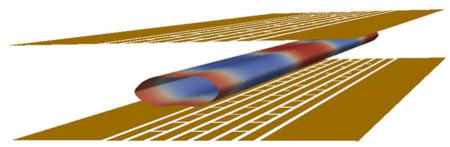
Graphical Abstract
SLIM utilize manipulations in ion conduits created with electric fields generated by applying potentials to arrays of electrodes patterned on two planar surfaces
Introduction
While mass spectrometry (MS) offers great sensitivity and adaptability to a variety of bioanalytical challenges, there is still a need for further improvements for many applications in attributes that include its sensitivity, specificity, and measurement throughput. The development of MS has benefitted from the ability to understand and model ion motion in electric and magnetic fields, and has led to the design of mass spectrometers optimized for a variety of applications. Inhomogenous electric fields (e.g., radio frequency; RF) are commonly used to confine and trap ions in MS.1 The effect of RF fields on ion motion in the presence of collisions with a dilute gas2 (i.e. collisional dampening) has led to the broad use of multipole RF ion guides (e.g., quadrupoles, hexapoles and octopoles, stacked-ring ion guides, etc., as well as the development of the ion funnel3, 4) to transfer and focus ions at intermediate (i.e. less than atmospheric) pressures. Ion mobility spectroscopy (IMS) separations also rely on manipulating ions at intermediate to ambient pressure where the collisions with the buffer gas are balanced by electric field.5 Different IMS-based separation gave rise to platforms such as constant field drift tube ion mobility spectrometry (DTIMS),6–8 field asymmetric ion mobility spectrometry (FAIMS),8, 9 differential mobility analysis (DMA),10 traveling wave ion mobility spectrometry (TWIMS),8, 11 trapped IMS (TIMS),12 overtone IMS (OIMS),13, 14 differential IMS (DIMS),15 and transversal modulation IMS (TM-IMS).16 In the classical DTIMS, ions are separated in IM according to their collision cross section ΩD with a buffer gas (usually N2 or He) as they travel under the influence of a weak electric field.17 The time t ions spend inside the drift cell is inversely proportional to its mobility K:5, 18
| (1) |
The electric field E is the voltage V applied across a drift cell of length L.
The reduced mobility K0 is the mobility normalized to pressure P (Torr) and temperature T (Kelvin).
| (2) |
The collision cross section ΩD is related to the mobility through:18
| (3) |
z is the charge state, e is the elementary charge, N is the number density, μ is the reduced mass of the ion-neutral pair, k is Boltzmann’s constant, Teff is the effective temperature and α is a correction factor less than 0.02 for ions whose mass is equal or greater than the mass of the neutral molecule. The effective temperature is the sum of the thermal temperature (due to the temperature of the buffer gas) and ion heating due to the drift field.
In TWIMS an oscillatory field is traditionally applied to a subset of a stack of ring electrodes, to create the TW in conjunction with out-of-phase RF field that is also co-applied to adjacent electrodes for radial ion confinement. The TW propagates along the intended direction of ion motion creating peaks and troughs (i.e. bins or traveling traps) along the ion path.19, 20 Depending on the ratio of ion velocity to the speed of the TW, three general ion behaviors are possible. If the ions have very high mobilities they ‘ride’ the wave (i.e. remain in a traveling trap) and exit the device unseparated.21 If the ion velocity is much lower than the speed of the wave, the waves have little effect on them and ions can be effectively trapped inside the device. At lower speeds, when the ion mobility does not allow the ions to maintain the wave velocity, ions separate based on their mobilities. Ions of higher mobility will move with the wave most of the time, while ions of lower mobility will more often be rolled over by a wave, and fall into the preceding traveling trap. The more rollover events ions experience, the slower they move through the device, giving rise to separations based on their mobilities. 19–21 In contrast to DTIMS, in TWIMS the relationship between the drift time t and mobility K is non-linear, requiring calibration to determine collision cross sections.21–23
New MS capabilities increasingly depend on the ability to conduct more effective and extended ion manipulations. However, suitable ion ‘optic’ designs for these applications based on conventional electrode structures and constructing platforms using such structures to enable new or more complex ion manipulations remain both challenging and costly. To this end, our laboratory has recently developed structures for lossless ion manipulations (SLIM) to enable much more effective and complex gas phase ion manipulations. SLIM are constructed from electric fields which are generated using arrays of electrodes patterned on two planar surfaces. These electrode arrays can be fabricated utilizing robust and mature printed-circuit board (PCB) technology, but 3D printing and other approaches can also be used to provide variations to these planar designs. The two surfaces are aligned in parallel and the electric fields are generated by application of appropriate voltages to the electrodes to create the SLIM ion confinement regions or conduits through which ions can be moved, separated by IMS, or otherwise manipulated. In this review, we detail the foundations of constant-field and traveling wave-based SLIM, describe SLIM modules developed to date and their initial evaluation, discuss their potential applications, and directions for future developments.
Ion Confinement in SLIM
Ions can be confined in RF ion guides, such as multipole ion guides and stacked-ring electrodes, by the application of out-of-phase RF waveforms to adjacent electrodes.1, 19 The inhomogeneous RF field created has a high effective potential close to the electrodes, preventing ions over a significant m/z range from approaching the electrodes. The effective potential drops off rapidly at short distances from the surfaces (distances similar to the spacing between electrodes).1, 24, 25 Unlike the circular geometry of stacked-ring ion guides, SLIM utilize two parallel surfaces generally having mirror image electrode arrays. In the first SLIM implementation, each surface contained ‘rung’ electrodes patterned to define an ion path, with co-applied RF (providing confinement ‘Y-direction’, preventing loss to the surfaces) and DC potentials (providing transport in the ‘Z-direction’) in conjunction with lateral DC ‘guard’ electrodes (enabling lateral ‘X-direction’ confinement), as shown in Figure 1. The net forces acting on ions are due to the electric fields (DC and RF) and the collisions with the background gas which rapidly damps ion motion. To a good approximation ions in a static gas move with a velocity determined by their mobility and the applied electric fields.26 Moreover, ions can be redirected on a different path essentially instantaneously by removing or appropriately changing the electric fields they experience. Computational methods (using in-house codes25 and SIMION simulations24) have been used to predict ion behavior in the RF and DC fields within SLIM.24, 25, 27 Simulations indicated the lossless confinement of ions can be achieved over a wide range of m/z at appropriate RF and DC potentials, consistent with the practical utility for performing ion mobility and other ion manipulations.24 The minimum and maximum m/z that can be effectively confined is also adjustable by changing the RF parameters (frequency and amplitude), similar to conventional RF multipole devices.28 Figure 2 shows typical ion confinement potentials that arise inside constant-field SLIM, where ions are retained within the potential well.29
Figure 1.

A) An illustration of one surface of a linear SLIM component. Opposing phases of RF are applied to adjacent RF rung electrodes and DC is co-applied to provide an electric field for ion drift motion. DC guard electrodes on either side of the ion path prevent loss in the lateral direction. B) A short SLIM linear IMS component.33
Figure 2.

Calculated effective potentials in the constant-field SLIM module design, showing the region of ion confinement.29 Adapted with permission from ref. 29, Copyright (2015) American Chemical Society.
In addition to the use of constant DC fields to drive ion motion, oscillatory fields, such as traveling waves (TWs), have also been utilized in SLIM.30 Unlike constant DC fields, TWs use temporally and spatially varying (and repeating) voltage profiles, where the maximum voltage needed does not depend on the path length. With the flexibility of SLIM to readily implement electrodes in complex and extended patterns, extremely long path lengths for ion mobility separations are possible in compact designs.31 Unlike constant field SLIM, where the initial designs used RF and DC fields applied simultaneously to each electrode, the TW SLIM applied RF and DC potentials to separate arrays of electrodes. This configuration not only simplified the power supply requirements but also eliminated the need for many electronic components (e.g. resistors and capacitors). In these designs, out-of-phase RF waveforms applied to adjacent electrode ‘strips’ aligned along the intended direction of ion motion and that were interleaved with segmented TW electrode arrays (Figure 3). Figure 4 shows the confinement due to the application of the RF fields in a SLIM, which creates an effective ion conduit. The additional potentials applied to the TW electrodes superimpose a series of troughs and peaks (i.e. ion ‘bins’ or traveling traps) along the ion path, as shown in the right panel of Figure 4. The combination of confinement provided by the RF and motion of the TW cause the ions to be efficiently moved and provide a basis for ion mobility separations in SLIM. Figure 3 shows a ‘6,5’ configuration, where RF is applied to 6 strips interleaved with 5 segmented TW electrode arrays. The same voltage profiles are applied to each set of 8 segmented TW electrodes along the ion path, and thus only 8 TW potentials need to be applied regardless of the length of the ion path. In our initial implementation, an elevated DC potential was applied to some number of each 8 electrodes and then stepped one electrode at a time at a given frequency in the direction of intended ion motion to create the TW. As we discuss below, this paradigm is broadly flexible, and SLIM TWIMS electrode designs have been adapted for moving ions through turns, between levels32 while conducting mobility separations using the same potentials, in some case augmented by the capability to apply additional potentials (particularly for ‘switching’ ion paths).
Figure 3.

Illustration of the traveling wave module showing the RF, traveling wave and guard electrodes. The DC voltage is applied to first 8 electrodes numbered 1 through 8 forming a traveling wave. The sequence is repeated through the entire ion path.30 Adapted with permission from ref. 30, Copyright (2015) American Chemical Society.
Figure 4.

Left panel shows the contour lines of the RF effective potentials in the plane normal to the axial direction of ion motion. Center panel shows iso-potential surface (at 100V) illustrating the confinement region forming ion conduits or pipes. Ions are confined to a conduit defined by the central oval region between the two surfaces. The right panel shows the TW potential distribution for an 80 TW electrode segment between the two SLIM surfaces and where ions are confined.53 Adapted with permission from ref. 53, Copyright (2016) American Chemical Society.
Ion Mobility Separations
Constant Field SLIM
The first generation of SLIM utilized constant DC fields to drive ion motion and perform ion mobility separations. The primary SLIM electrodes were 1.5 mm long and 5 mm wide with RF superimposed on the DC gradient potentials (Figure 1). A resistive voltage divider network was used to establish the gradient across the electrodes while a capacitor chain enabled the superimposed RF. DC-only guard electrodes, 5.25 mm long and 6 mm wide, were used to provide a lateral confinement (i.e. to the sides between surfaces; Figures 1 and 2). Initial experiments with the constant field SLIM evaluated the IMS resolving power achievable with a 30 cm linear path.33 Ion current was measured at multiple points throughout the ion path and showed no loss of ions. IMS measurements were then made using a SLIM module with a linear path of 45.7 cm. With proper tuning of the guard (~10 V biased above gradient voltage) and RF voltages (> 300 Vp-p), transmission plateaued, and resolving power close to theoretical prediction was achieved (~60 for singly charged ions). Recently, Allen et al. reported the construction of a 45.7 cm long SLIM module in order to measure ion mobility of proteins under native conditions.34 The authors reported cross section measurements for native proteins of masses that ranged from 12.4–145 kDa and matched those reported in the literature (Figure 5), concluding that SLIM provide a gentle environment enabling preservation of the native-like protein structures.
Figure 5.

Collision cross sections with IMS with nitrogen determined using SLIM (ΩSLIM) versus those reported using a first-generation RF-confining drift cell (ΩRFG1, blue circles) or determined using a second-generation RF-confining drift cell (ΩRFG2, red squares) of selected native-like ions of cytochrome c monomer (CYTC), concanavalin A monomer (CONA(mon.)), concanavalin A dimer (CONA(dim.)), avidin tetramer (AVD), concanavalin A tetramer (CONA(tet.)), and glyceraldehyde-3-phosphate dehydrogenase tetramer (G3PD). The dashed line represents a one-to-one relationship between values determined using the two devices (ΩSLIM = ΩRFG2/G1).34 Adapted with permission from ref. 34, Copyright (2016) American Chemical Society.
Key to the utility of SLIM is the ability to make effective use of the 2D space between the surfaces; thus the ability to make turns without ion losses, and ideally loss of IMS resolving power, is of crucial importance. We thus explored a second design that included a 90° turn and showed resolving powers similar to the SLIM linear arrangement by optimizing the SLIM potentials; i.e. without any significant “race track” effect.24, 27 Thus, SLIM can incorporate multiple turns without any significant loss of resolving power.33
In addition to linear and turn ion paths, an ion switch was also introduced.35 The switch has similar geometry as a turn, but included a guard electrode region (Figure 6; ‘Switching Guard’) at the base of the turn that could be biased with higher voltage as well as rung electrode in the orthogonal direction (Figure 6, Switching Rung) that could be lowered by ~5 V to effect ion turning. By precisely timing the switching, specific mobility ranges can be selected (Figure 7) without perturbing ions of other mobilities. Selecting ions of specific mobilities was demonstrated previously using grids by Clemmer et al. to achieve better IMS-IMS separations and to perform overtone mobility separation.36, 37 However, unlike ion switches used in SLIM, grids have finite transmission leading to ion losses that increase as a function of number of grids used which was removed by Zucker et al. to avoid these ion losses.14 While in the collinear arrangement used by Clemmer et al. ions not selected were lost, the SLIM switches were used to divert ions to a different path for further manipulations. In another SLIM arrangement an ion trapping region was included in the orthogonal section of the switch. The ability to do an initial IMS separation followed by switching and trapping ions of a specific mobility and then ion accumulating over multiple injections was demonstrated for melittin ions.38
Figure 6.

The SLIM dynamic ion switch component. The switching guard voltage is raised by 100 V to direct the ions orthogonal to their original drift path.33, 35
Figure 7.

A) An IMS-MS experiment for a mixture of 9 peptides. B) Dynamic switching of ions from the 9 peptides arriving to the switch 7–8 ms after the ion packet release.35
Traveling Wave SLIM (TW SLIM)
While the use of linear DC fields for IMS in SLIM are effective, they inherently limit either the path length or field strength for IM separations due to excessive voltage requirements. The use of TW, on the other hand, does not limit the path length as the same TW is repeatedly used throughout the entire device. The first implementation of a TW SLIM was a 30 cm long linear module where the ion transmission was shown to be essentially lossless.30 The 30 cm TW SLIM module provided an ion mobility resolution for the m/z 622 and 922 (Ω = 202.9 and 243.0 Å2, respectively)39 of ~10. (The resolution is the distance between the two peaks divided by the average full width at half maximum.)
Another TW SLIM module was developed to evaluate the effect of multiple 90° turns and U-turn on ion transmission and IMS resolution (Figure 8) that included 16 turns and had a total length of 44 cm. Ion transmission was lossless and the maximum IMS resolution of ~11 observed was similar to that of a linear TW SLIM module of similar length.31 The performance achieved provided the foundation for development of extended ion paths by making multiple U-turns in compact IMS module. We then developed a ~13 m serpentine path TW SLIM IMS module40 that utilized a pair of surfaces (45.9-cm × 32.5-cm) spaced by a 2.75 mm gap. Figure 9 shows a schematic diagram and a photo of one SLIM surface showing the electrode arrangement. Similar to other TW SLIM modules, the 13 m path module utilized three different sets of electrodes (Figure 9B inset); guard, RF, and TW electrodes. As shown in Figure 10, ion current measurements at different positions along the 13 m path indicated no loss of ions. The SLIM module was also evaluated for robustness and demonstrated no degradation of sensitivity or performance over 8 hours of continuous operation (Figure 10). This TW SLIM module provided more than a 40-fold increase in path length when compared to the 30 cm module and provided a resolution of ~47 for Agilent tuning mix m/z 622 and 922 ions (resolving power Ω/ΔΩ ~240), which is ~5-fold higher than the 30 cm TW SLIM and 6-fold higher than a 90 cm DTIMS instrument.40 The peak capacity was estimated at >200 and the peak generation rate was ~350 s−1 which is approximately two orders of magnitude greater than typically feasible with liquid chromatography. This high peak generation rate for IMS stems from the fast movement of ions in the gas phase relative to liquid phase. However, due to the inherit dependence of mobility on mass (see equation 3) the orthogonality of IMS and MS is lower than LC and MS. While the orthogonality of IMS and MS can be improved, by e.g. using different buffer gases or doping the buffer gas with vapors that can change the separation parameters, 41–45 we emphasize that the major benefit of an improved separation (e.g. greater peak capacity) is the reduced mixture complexity delivered to the MS at any given point, and the resulting improvements in detection limits, S/N, etc. In addition, IMS separations are not affected by e.g. degradation of a stationary phase or variations in elution gradient profiles as in LC,46–48 providing IMS with increased reproducibility compared to LC.49
Figure 8.

A schematic diagram of a multi-turn TW-SLIM.31 Adapted with permission from ref. 31, Copyright (2016) American Chemical Society.
Figure 9.

A) Schematic diagram of a TW-SLIM IMS-MS. B) Photo of one of the two TW SLIM surfaces showing the electrodes arrangement with all turns and illustration of a “U” turn (inset) showing the RF, traveling wave, and guard electrodes.40 Adapted with permission from ref. 40, Copyright (2016) American Chemical Society.
Figure 10.

(A) Agilent tuning mix ion current measured as a function of distance from the entrance to the TW SLIM module at a TW speed of 124 m/s, TW amplitude of 30 V, guard bias of 5 V, RF amplitude of 220 Vp-p at 650 kHz, and 2.75 mm gap at 4.00 Torr. Error bars represent standard deviations from triplicate measurements. (B) Total ion current (TIC) was measured over 8 h, and the mass spectrum was obtained by being averaged from 0 to 8 h with the above identical conditions.40 Adapted with permission from ref. 40, Copyright (2016) American Chemical Society.
The 13 m TW SLIM IMS-MS was used to evaluate separations achievable for several peptide, lipid and sugar isomers indistinguishable by MS alone and also problematic with currently available IMS-MS platforms. Examples included Lacto-N-fucopentaose I/Lacto-N-fucopentaose II (Figure 11), cellopentaose/maltopentaose/mannopentaose, cis vs. trans double bond position in lipids ((PE(18:1(9Z)/18:1(9Z))/(PE(18:1(9E)/18:1(9E))), and a subtle peptide isomer pair YGGFI/YGGFL.50 In all cases, where DTIMS provided little or no useful separation, the 13 m SLIM IMS provided significant separations. Although complete (i.e. peak baseline) separations were not obtained in some cases, it is now clear that much longer path length SLIM IMs should be feasible. In addition, we are presently exploring multi-pass versions of the present platform, where increased resolution can be obtained by multiple transits of the same 13 m path, until ions are switched to the MS.51 We believe the practical utility of these approaches will be greatly enhanced by the abilities to not only inject and analyze much larger ion populations, but also to mitigate the gradual increase in peak width and decreased signal intensities with longer path separations due to diffusion and other factors; new capabilities enabled by SLIM we discuss in the next section. We anticipate that the long serpentine path and multi-pass variations of TW SLIM IMS will have broad applicability due to the combination of high speed, sensitivity and IMS resolution achievable.
Figure 11.

A) A mass spectrum of a sample containing mixture of ions obtained with a 13-m serpentine path TW SLIM IMS module. B) IMS separation for a mixed sample obtained by TW SLIM at the optimum conditions: TW speed of 148 m/s, TW amplitude of 30 V, guard bias of 5 V, RF amplitude of 220 Vp-p at 650 kHz, and 2.75 mm gap at 3.00 Torr. C) Nested mass and IMS spectrum. (D) Extracted TW SLIM IMS separations for individually nanoelectrosprayed LNFPi (blue) and LNFPii (red) (m/z [M + Na]+ = 876) ions and (E) a mixture of LNFPi and LNFPii (m/z [M + Na]+ = 876). (F) A 90 cm DTIMS separations for LNFPi and LNFPii (m/z [M + Na]+ = 876) ions obtained at 19 V/cm is shown for comparison.40 Adapted with permission from ref. 40, Copyright (2016) American Chemical Society.
The compression of ion populations and IMS peaks in SLIM
An IMS separation is usually initiated with a tight, well-defined ion packet or pulse. As the ion pulse travels through the drift cell separation may result in multiple packets and, with diffusion or any field imperfections, inevitably causing each ion packet to broaden. As the drift time increases, as needed to achieve greater resolution, the peak broadening leads to a drop in peak intensity, ultimately challenging detection capabilities. A SLIM ‘compression’ process was developed to counter this peak broadening during the course of a separation and thus create narrower peaks with higher intensity and enabling the use of longer drift paths. The theoretical foundation for ion peak compression was first introduced in the context of constant field IMS.52 An ion packet traveling in a constant field could be subjected to a linearly decreasing electric field for a short time period which would cause the ions in the tail of the peak to travel faster than those in the front of the peak resulting in narrowing of the peak width. Ion peak compression applied to partially separated ion peaks could lead to increased peaks heights, potentially with some small reduction in resolution which could be quickly recovered by allowing ions to drift longer in the constant field. However, implementation was challenging in the context of constant field IMS which led to the development of a compression ratio ion mobility programming (CRIMP) approach in TW SLIM.53 In an IMS separation, an ion peak or packet is distributed over a set of waves (or bins) where the regions between two consecutive waves (troughs) act as a small trap. CRIMP relies on the redistribution of ions dispersed over an ion path by effectively combining some number of adjacent ion TW ‘bins’ into one as they move along a path, and thus providing a narrower temporal width for any ion distribution or separation. Merging the contents of two or more of these small traps at the interface with a second region where the TW moves intermittently, and thus at a slower average speed (in ‘stuttering traps’, ST), leads to redistributing the ion population into a smaller number of TW bins and thus spatially compressed. After the regrouping of ions the speed of the ST returns to the non-stuttering TW speed before ions exit the CRIMP region so as to provide temporal peak compression. Figure 12 shows the results for using CRIMP on two peaks that are 25 ms wide (due to the injection of a large band of ions) and separated by 86 ms. Applying a 7-fold compression ratio (CR=7) resulted in narrowing the two peaks followed by passage through an additional 3 m increased the resolution achieved by a factor of ~3.8. While maintaining the same number of ions, CRIMP can be used to improve the signal to noise ratio in situations where the peak broadening becomes excessive such as in long path multi-pass IMS separations.51 Perhaps just as important, the use of CRIMP in SLIM provides the basis for injecting or starting with larger ion populations to ultimately provide greater sensitivity and ion utilization efficiency, and circumventing limitations due to excessive space charge by applying compression after separation has naturally reduced space charge. CRIMP can be applied periodically during extended separations, or just prior to MS detection, and is broadly applicable with the only limitation being the need to avoid over compression that can cause a loss of resolution, or result in excessive space charge.
Figure 12.

A) IMS separations for m/z 622 and 922 starting with a 25 ms wide packet of ions introduced from the source region and then subjected to a 9-m separation, providing a resolution of 3.45; B) With additional application of compression ratio of 7 and then reverting back to separation mode for an additional 3 m, resulting in a resolution of 13.1.53 During the surfing mode, the ions remain confined in traveling traps and exit the device unseparated. Adapted with permission from ref. 53, Copyright (2016) American Chemical Society.
Ion Trapping
Constant Field SLIM
A 30.5 cm constant field SLIM module was initially used to explore ion trapping in SLIM. The trapping was accomplished by applying appropriate voltages to an entrance section (~7.6 cm), trapping section (~15.2 cm), and exit section (~7.6 cm). During ion storage, a DC gradient of 2 V/cm was applied to the entrance and exit sections while no gradient was applied to the trapping section. Using this arrangement, tetroctylammonium (m/z 466.3) and tetradodecylammonium (m/z 690.6) ions could be stored at 4 Torr N2 essentially losslessly for 5 hours.29 The charge capacity of SLIM was estimated based on the balance between the confinement field and the field produced by the charges (from ions) based on Gauss law.25 The number of charges can be calculated as , where Q is the total charges in Coulombs, e is the elementary charge, εo is the relative permittivity of air, and F is electric field flux produced by the stored charges. From the effective potential calculation, the field can be estimated and the charge capacity can be calculated. The upper limit for the charge capacity was estimated at ~108 charges in the 15.2 cm SLIM trapping region. Experimental determination of the charge capacity was made by integrating the peak area of the ion current pulses released from the SLIM device after they were trapped and then released29 for sufficient period of time, wherein: . I is the measured current in time duration dt and e is the elementary charge. The maximum trapping capacity of this particular SLIM module was measured at ~6×10⁷ charges (Figure 13).
Figure 13.

Measurement of the charge capacity and trapping efficiency of the SLIM trap. A) The current detected from ion pulses released from the SLIM trap for different filling times (indicated). Also shown is the typical measured continuous ion current (~10 pA). B) The numbers of accumulated charges (solid black triangles) and the corresponding trapping efficiency (open red squares).29 Adapted with permission from ref. 29, Copyright (2015) American Chemical Society.
Trapping and manipulation of large ion populations in SLIM
We developed a ‘flat funnel’ TW SLIM module fabricated from ~46×33 cm surfaces that included a funnel-shaped electrode arrangement to explore capabilities for greatly increasing trapped ion populations, particularly for use with IMS separations.54 Three independently-controlled traveling waveforms provided ion transmission from the source to the trap section (i.e., ion filling), the release of ions from the trapping section (i.e., ion ejection) and transferring ions through a funnel-shaped section to a time-of-flight MS (Figure 14). The flat funnel was operated at ~3 Torr and used two TWs that were applied to two sets of interleaving TW electrodes in the trap section. One of the TWs was used to transfer ions into the trap from the source while another TW, initially grounded during ion filling, was responsible for releasing ions from the trap. The directions of the two TWs were orthogonal to each other to provide fast ion ejection. No grids were utilized to prevent ions from leaving the trap section, but rather a bias voltage was applied to two of the TW electrodes at the intersection between the trap and funnel sections, and was sufficient to hold ions in the trap section. The amplitude of the TW that introduced ions into the trap section was found to have a significant impact on the trap capacity. Lower TW amplitudes were found to result in better trapping efficiencies. This trapping setup resulted in a maximum charge capacity of ~3.2×10⁸ charges with a quantitative linear range of up to ~5×10⁷ charges and a release time of 3 ms. The trap section of the flat funnel had a dimensions of approximately 280×6 mm indicating a linear charge capacity of ~2×10⁵ charges/mm (for efficient and unbiased accumulation) and a maximum capacity of ~1×10⁶ charges/mm. As noted earlier, the use of CRIMP makes much larger trapping volumes useful, and at present given capabilities for extended ion storage and other manipulations in SLIM, it is unclear what the practical upper limits are to ion population sizes.
Figure 14.

Representative schematics of the A) TW SLIM ‘flat funnel‘ (FF) IMS-MS design; B) TW SLIM FF intersection region showing the electrode arrangements of RF, TW, guard electrodes in different sections and dual gate (G1, G2) electrodes. The IFT was used in continuous mode.54 Adapted with permission from ref. 54, Copyright (2016) American Chemical Society.
Collision Induced Dissociation
There is great utility in conducting ion fragmentation at higher pressures and SLIM is well-suited for this capability. Collision induced dissociation (CID) has already been illustrated with a constant field SLIM module operated at 265 mTorr.55 The SLIM module consisted of three discrete but integrated regions. The first two regions had independent DC gradients and were followed by a region designed to act as a planar quadrupole. Ion dissociation was achieved by accelerating ions between the first two regions. After dissociation, the ion beam consisting of fragments and the remaining parent ions was focused in the planar quadrupole region before it was transmitted to a QTOF MS. Results for the singly charged leucine encephalin ion showed a 62% CID efficiency (Figure 15). The CID was also demonstrated for a mixture of 9 peptides showing the ability of SLIM to perform multiplexed fragmentation. By performing fragmentation in SLIM devices, multiple functions can be seamlessly coupled (i.e. IMS, trapping, and fragmentation). Beyond this initial demonstration, we note that SLIM utility should extend well beyond CID, due to both the extended storage feasible, and should be especially attractive for photoactivation/photodissociation due to the easy optical access.
Figure 15.

Representative spectra of protonated leucine enkephalin at 265 mTorr, 750 kHz, 200 Vp-p RF. (a) VCID = 0. (b) VCID = 30, CID efficiency = 62%. 55 Adapted with permission from ref. 55, Copyright (2016) Springer.
Summary and Future Directions
In this review we outlined the basis for ion confinement and ion motion in SLIM and illustrated the flexibility for building devices from electric fields generated using arrays of electrodes in various arrangements to effect the desired ion manipulations. Theoretical modeling and ion motion simulations have been instrumental for understanding behavior of ions inside individual SLIM components. Initial SLIM have utilized electric fields generated by arrays of electrodes on surfaces have been fabricated using PCB technology due to its low cost and fast prototyping, but other technologies such as 3D printing can be also used. The planar geometry of SLIM offers advantages in terms of flexibility for evaluating multiple SLIM approaches or designs within the same module, speeding overall development times. All SLIM modules to date have demonstrated capabilities for lossless storage for a broad range of manipulations. Although the SLIM studied to date were implemented at pressures of 2–4 Torr, operations an order of magnitude higher or lower in pressure should be feasible by optimizing the RF and electric field parameters. More sophisticated SLIM modules are currently being developed which will further demonstrate the ability of SLIM to be utilized in new applications and address a range of current challenges.
The flexibility of SLIM opens the door to more sophisticated and extended ion manipulations. Multi-pass SLIM IMS modules based on the 13 m TW SLIM IMS should provide opportunities for separating isomeric molecules with very similar structures. These devices allow the resolution to be further increased by passing ions multiple times through the extended serpentine path.51 Additionally, by integrating CRIMP with multi-pass serpentine path SLIM it is anticipated that we will be able to greatly increase the number of possible passes by occasionally compressing the diffused ion packets (i.e. IMS peaks), thus not only improving the sensitivity but providing much greater path lengths for even greater IMS resolution. We also anticipate SLIM having the ability to move ions efficiently different ‘levels’, enabling the development of multi-level SLIM that would allow the much greater path lengths for IMS separations, as well as other extended capabilities (e.g., different reaction regions, arrays of ion trapping regions).32 Performing gas phase ion chemistry, such as ion-ion or ion-neutral reactions, will open additional opportunities for SLIM, both in conjunction with MS-based platforms, and potentially as stand-alone devices.
Acknowledgments
We are grateful to the contribution of various scientists in the course of SLIM development. We thank Dr. Xueyun Zheng, Dr. Roza Wojcik, Dr. Xinyu Zhang, Dr. Aleksey V Tolmachev, Dr. Tsung-Chi Chen, Dr. Jonathan T. Cox, Dr. Xing Zhang, Dr. Keqi Tang, Randolph V. Norheim, Spencer A Prost, and Gordon A. Anderson. Portions of this research were supported by the Laboratory Directed Research and Development (LDRD) program at the Pacific Northwest National Laboratory, National Institutes of Health (NIH) NIGMS Proteomics Research Resource under grant P41 GM103493, and by the Department of Energy Office of Biological and Environmental Research Genome Sciences Program under the Pan-Omics project. Work was performed in the Environmental Molecular Sciences Laboratory (EMSL), a DOE national scientific user facility at the Pacific Northwest National Laboratory (PNNL) in Richland WA. PNNL is operated by Battelle for the DOE under Contract DE-AC05-76RL0 1830.
Biography

From left to right: Yehia Ibrahim is a senior scientist developing new mass spectrometry technologies related to ion mobility, e.g. SLIM; Ahmed Hamid is a postdoctoral researcher developing SLIM; Sandilya Garimella is a scientist interested in ion simulations and gas flow modeling; Ian Webb is a scientist interested in enabling biological applications using SLIM; Richard D. Smith is Battelle Fellow interested developing advanced capabilities for biological research based upon developments in separations with mass spectrometry; Erin Baker is senior scientist interested in applying advanced ion mobility approaches to biological challenges; Liulin Deng is postdoctoral researcher developing advance mass spectrometry approaches, including SLIM.
References
- 1.Gerlich D. Adv Chem Phys. 1992;82:1–176. [Google Scholar]
- 2.Douglas DJ, French JB. J Am Soc Mass Spectrom. 1992;3:398–408. doi: 10.1016/1044-0305(92)87067-9. [DOI] [PubMed] [Google Scholar]
- 3.Ibrahim Y, Tang K, Tolmachev AV, Shvartsburg AA, Smith RD. J Am Soc Mass Spectrom. 2006;17:1299–1305. doi: 10.1016/j.jasms.2006.06.005. [DOI] [PMC free article] [PubMed] [Google Scholar]
- 4.Kelly RT, Tolmachev AV, Page JS, Tang K, Smith RD. Mass Spectrom Rev. 2010;29:294–312. doi: 10.1002/mas.20232. [DOI] [PMC free article] [PubMed] [Google Scholar]
- 5.Ion Mobility Spectrometry - Mass Spectrometry: Theory and Applications. CRC Press; Boca Raton: 2010. [Google Scholar]
- 6.Dugourd P, Hudgins RR, Clemmer DE, Jarrold MF. Rev Sci Instrum. 1997;68:1122–1129. [Google Scholar]
- 7.Dodds JN, May JC, McLean JA. Anal Chem. 2017;89:952–959. doi: 10.1021/acs.analchem.6b04171. [DOI] [PMC free article] [PubMed] [Google Scholar]
- 8.Cumeras R, Figueras E, Davis C, Baumbach JI, Gracia I. Analyst. 2015;140:1376–1390. doi: 10.1039/c4an01100g. [DOI] [PMC free article] [PubMed] [Google Scholar]
- 9.Guevremont R. J Chromatogr A. 2004;1058:3–19. [PubMed] [Google Scholar]
- 10.de la Mora JF, de Juan L, Eichler T, Rosell J. TrAC, Trends Anal Chem. 1998;17:328–339. [Google Scholar]
- 11.Giles K, Wildgoose JL, Langridge DJ, Campuzano I. Int J Mass Spectrom. 2010;298:10–16. [Google Scholar]
- 12.Michelmann K, Silveira JA, Ridgeway ME, Park MA. J Am Soc Mass Spectrom. 2015;26:14–24. doi: 10.1007/s13361-014-0999-4. [DOI] [PubMed] [Google Scholar]
- 13.Ewing MA, Conant CRP, Zucker SM, Griffith KJ, Clemmer DE. Anal Chem. 2015;87:5132–5138. doi: 10.1021/ac504555u. [DOI] [PubMed] [Google Scholar]
- 14.Zucker SM, Ewing MA, Clemmer DE. Anal Chem. 2013;85:10174–10179. doi: 10.1021/ac401568r. [DOI] [PMC free article] [PubMed] [Google Scholar]
- 15.Rus J, Moro D, Sillero JA, Royuela J, Casado A, Estevez-Molinero F, Fernández de la Mora J. Int J Mass Spectrom. 2010;298:30–40. [Google Scholar]
- 16.Vidal-de-Miguel G, Macía M, Cuevas J. Anal Chem. 2012;84:7831–7837. doi: 10.1021/ac301127u. [DOI] [PubMed] [Google Scholar]
- 17.McDaniel EW, Mason EA. The Mobility and Diffusion of Ions in Gases. Wiley; New York: 1973. [Google Scholar]
- 18.Revercomb HE, Mason EA. Anal Chem. 1975;47:970–983. [Google Scholar]
- 19.Giles K, Pringle SD, Worthington KR, Little D, Wildgoose JL, Bateman RH. Rapid Commun Mass Spectrom. 2004;18:2401–2414. doi: 10.1002/rcm.1641. [DOI] [PubMed] [Google Scholar]
- 20.Giles K, Williams JP, Campuzano I. Rapid Commun Mass Spectrom. 2011;25:1559–1566. doi: 10.1002/rcm.5013. [DOI] [PubMed] [Google Scholar]
- 21.Shvartsburg AA, Smith RD. Anal Chem. 2008;80:9689–9699. doi: 10.1021/ac8016295. [DOI] [PMC free article] [PubMed] [Google Scholar]
- 22.Bush MF, Campuzano IDG, Robinson CV. Anal Chem. 2012;84:7124–7130. doi: 10.1021/ac3014498. [DOI] [PubMed] [Google Scholar]
- 23.Chawner R, McCullough B, Giles K, Barran PE, Gaskell SJ, Eyers CE. J Proteome Res. 2012;11:5564–5572. doi: 10.1021/pr3005327. [DOI] [PubMed] [Google Scholar]
- 24.Garimella SV, Ibrahim YM, Webb IK, Tolmachev AV, Zhang X, Prost SA, Anderson GA, Smith RD. J Am Soc Mass Spectrom. 2014;25:1890–1896. doi: 10.1007/s13361-014-0976-y. [DOI] [PMC free article] [PubMed] [Google Scholar]
- 25.Tolmachev AV, Webb IK, Ibrahim YM, Garimella SVB, Zhang XY, Anderson GA, Smith RD. Anal Chem. 2014;86:9162–9168. doi: 10.1021/ac502054p. [DOI] [PMC free article] [PubMed] [Google Scholar]
- 26.Baker ES, Clowers BH, Li FM, Tang K, Tolmachev AV, Prior DC, Belov ME, Smith RD. J Am Soc Mass Spectrom. 2007;18:1176–1187. doi: 10.1016/j.jasms.2007.03.031. [DOI] [PMC free article] [PubMed] [Google Scholar]
- 27.Garimella SVB, Ibrahim YM, Webb IK, Ipsen AB, Chen TC, Tolmachev AV, Baker ES, Anderson GA, Smith RD. Analyst. 2015;14:6845–6852. doi: 10.1039/c5an00844a. [DOI] [PMC free article] [PubMed] [Google Scholar]
- 28.Austin WE, Holme AE, Leck JH. In: Quadrupole Mass Spectrometry and Its Applications. Dawson PH, editor. Elsevier; 1976. [Google Scholar]
- 29.Zhang XY, Garimella SVB, Prost SA, Webb IK, Chen TC, Tang KQ, Tolmachev AV, Norheim RV, Baker ES, Anderson GA, Ibrahim YM, Smith RD. Anal Chem. 2015;87:6010–6016. doi: 10.1021/acs.analchem.5b00214. [DOI] [PMC free article] [PubMed] [Google Scholar]
- 30.Hamid AM, Ibrahim YM, Garimella SV, Webb IK, Deng L, Chen TC, Anderson GA, Prost SA, Norheim RV, Tolmachev AV, Smith RD. Anal Chem. 2015;87:11301–11308. doi: 10.1021/acs.analchem.5b02481. [DOI] [PMC free article] [PubMed] [Google Scholar]
- 31.Hamid AM, Garimella SVB, Ibrahim YM, Deng L, Zheng X, Webb IK, Anderson GA, Prost SA, Norheim RV, Tolmachev AV, Baker ES, Smith RD. Anal Chem. 2016;88:8949–8956. doi: 10.1021/acs.analchem.6b01914. [DOI] [PMC free article] [PubMed] [Google Scholar]
- 32.Ibrahim YM, Hamid AM, Cox JT, Garimella SVB, Smith RD. Anal Chem. 2017;89:1972–1977. doi: 10.1021/acs.analchem.6b04500. [DOI] [PMC free article] [PubMed] [Google Scholar]
- 33.Webb IK, Garimella SV, Tolmachev AV, Chen TC, Zhang X, Norheim RV, Prost SA, LaMarche B, Anderson GA, Ibrahim YM, Smith RD. Anal Chem. 2014;86:9169–9176. doi: 10.1021/ac502055e. [DOI] [PMC free article] [PubMed] [Google Scholar]
- 34.Allen SJ, Eaton RM, Bush MF. Anal Chem. 2016;88:9118–9126. doi: 10.1021/acs.analchem.6b02089. [DOI] [PubMed] [Google Scholar]
- 35.Webb IK, Garimella SV, Tolmachev AV, Chen TC, Zhang X, Cox JT, Norheim RV, Prost SA, LaMarche B, Anderson GA, Ibrahim YM, Smith RD. Anal Chem. 2014;86:9632–9637. doi: 10.1021/ac502139e. [DOI] [PMC free article] [PubMed] [Google Scholar]
- 36.Merenbloom SI, Koeniger SL, Valentine SJ, Plasencia MD, Clemmer DE. Anal Chem. 2006;78:2802–2809. doi: 10.1021/ac052208e. [DOI] [PubMed] [Google Scholar]
- 37.Kurulugama RT, Nachtigall FM, Lee S, Valentine SJ, Clemmer DE. J Am Soc Mass Spectrom. 2009;20:729–737. doi: 10.1016/j.jasms.2008.11.022. [DOI] [PMC free article] [PubMed] [Google Scholar]
- 38.Chen TC, Ibrahim YM, Webb IK, Garimella SV, Zhang X, Hamid AM, Deng L, Karnesky WE, Prost SA, Sandoval JA, Norheim RV, Anderson GA, Tolmachev AV, Baker ES, Smith RD. Anal Chem. 2016;88:1728–1733. doi: 10.1021/acs.analchem.5b03910. [DOI] [PMC free article] [PubMed] [Google Scholar]
- 39.Hines KM, May JC, McLean JA, Xu L. Anal Chem. 2016;88:7329–7336. doi: 10.1021/acs.analchem.6b01728. [DOI] [PMC free article] [PubMed] [Google Scholar]
- 40.Deng L, Ibrahim YM, Hamid AM, Garimella SVB, Webb IK, Zheng X, Prost SA, Sandoval JA, Norheim RV, Anderson GA, Tolmachev AV, Baker ES, Smith RD. Anal Chem. 2016;88:8957–8964. doi: 10.1021/acs.analchem.6b01915. [DOI] [PMC free article] [PubMed] [Google Scholar]
- 41.Waraksa E, Perycz U, Namiesnik J, Sillanpaa M, Dymerski T, Wojtowicz M, Puton J. Trac-Trends Anal Chem. 2016;82:237–249. [Google Scholar]
- 42.Meyer NA, Root K, Zenobi R, Vidal-de-Miguel G. Anal Chem. 2016;88:2033–2040. doi: 10.1021/acs.analchem.5b02750. [DOI] [PubMed] [Google Scholar]
- 43.Fernandez-Maestre R, Wu C, Hill HH. Int J Mass Spectrom. 2010;298:2–9. doi: 10.1016/j.ijms.2010.08.009. [DOI] [PMC free article] [PubMed] [Google Scholar]
- 44.Davidson KL, Bush MF. Anal Chem. 2017;89:2017–2023. doi: 10.1021/acs.analchem.6b04605. [DOI] [PubMed] [Google Scholar]
- 45.Asbury GR, Hill HH. Anal Chem. 2000;72:580–584. doi: 10.1021/ac9908952. [DOI] [PubMed] [Google Scholar]
- 46.Watrous JD, Henglin M, Claggett B, Lehmann K, Larson MG, Cheng S, Jain M. Anal Chem. 2017;89:1399–1404. doi: 10.1021/acs.analchem.6b04337. [DOI] [PMC free article] [PubMed] [Google Scholar]
- 47.Piehowski PD, Petyuk VA, Orton DJ, Xie F, Ramirez-Restrepo M, Engel A, Lieberman AP, Albin RL, Camp DG, Smith RD, Myers AJ. J Proteome Res. 2013;12:2128–2137. doi: 10.1021/pr301146m. [DOI] [PMC free article] [PubMed] [Google Scholar]
- 48.Jaitly N, Monroe ME, Petyuk VA, Clauss TRW, Adkins JN, Smith RD. Anal Chem. 2006;78:7397–7409. doi: 10.1021/ac052197p. [DOI] [PubMed] [Google Scholar]
- 49.Zhou Z, Shen X, Tu J, Zhu ZJ. Anal Chem. 2016;88:11084–11091. doi: 10.1021/acs.analchem.6b03091. [DOI] [PubMed] [Google Scholar]
- 50.Deng L, Ibrahim YM, Baker ES, Aly NA, Hamid AM, Zhang X, Zheng X, Garimella SVB, Webb IK, Prost SA, Sandoval JA, Norheim RV, Anderson GA, Tolmachev AV, Smith RD. Chemistry Select. 2016;1:2396–2399. doi: 10.1002/slct.201600460. [DOI] [PMC free article] [PubMed] [Google Scholar]
- 51.Deng L, Webb IK, Garimella SVB, Hamid AM, Zheng X, Norheim RV, Prost SA, Anderson GA, Sandoval JA, Baker ES, Ibrahim YM, Smith RD. Anal Chem. 2017 doi: 10.1021/acs.analchem.7b00185. Submitted. [DOI] [PMC free article] [PubMed] [Google Scholar]
- 52.Garimella SVB, Ibrahim YM, Tang K, Webb IK, Baker ES, Tolmachev AV, Chen TC, Anderson GA, Smith RD. J Am Soc Mass Spectrom. 2016;27:1128–1135. doi: 10.1007/s13361-016-1371-7. [DOI] [PMC free article] [PubMed] [Google Scholar]
- 53.Garimella SVB, Hamid AM, Deng L, Ibrahim YM, Webb IK, Baker ES, Prost SA, Norheim RV, Anderson GA, Smith RD. Anal Chem. 2016;88:11877–11885. doi: 10.1021/acs.analchem.6b03660. [DOI] [PMC free article] [PubMed] [Google Scholar]
- 54.Deng L, Ibrahim YM, Garimella SVB, Webb IK, Hamid AM, Norheim RV, Prost SA, Sandoval JA, Baker ES, Smith RD. Anal Chem. 2016;88:10143–10150. doi: 10.1021/acs.analchem.6b02678. [DOI] [PMC free article] [PubMed] [Google Scholar]
- 55.Webb IK, Garimella SV, Norheim RV, Baker ES, Ibrahim YM, Smith RD. J Am Soc Mass Spectrom. 2016;27:1285–1288. doi: 10.1007/s13361-016-1397-x. [DOI] [PMC free article] [PubMed] [Google Scholar]