Abstract
The von Mises (VM) stress is a common stress measure for finite element models of tissue mechanics. The VM failure criterion, however, is inherently isotropic, and therefore may yield incorrect results for anisotropic tissues, and the relevance of the VM stress to anisotropic materials is not clear. We explored the application of a well-studied anisotropic failure criterion, the Tsai–Hill (TH) theory, to the mechanically anisotropic porcine aorta. Uniaxial dogbones were cut at different angles and stretched to failure. The tissue was anisotropic, with the circumferential failure stress nearly twice the axial (2.67 ± 0.67 MPa compared to 1.46 ± 0.59 MPa). The VM failure criterion did not capture the anisotropic tissue response, but the TH criterion fit the data well (R2 = 0.986). Shear lap samples were also tested to study the efficacy of each criterion in predicting tissue failure. Two-dimensional failure propagation simulations showed that the VM failure criterion did not capture the failure type, location, or propagation direction nearly as well as the TH criterion. Over the range of loading conditions and tissue geometries studied, we found that problematic results that arise when applying the VM failure criterion to an anisotropic tissue. In contrast, the TH failure criterion, though simplistic and clearly unable to capture all aspects of tissue failure, performed much better. Ultimately, isotropic failure criteria are not appropriate for anisotropic tissues, and the use of the VM stress as a metric of mechanical state should be reconsidered when dealing with anisotropic tissues.
Keywords: biomechanics, failure criteria, anisotropy, von Mises stress
1. Introduction
Accurate failure prediction techniques are essential to assess and understand biological tissues at risk of failure. In the case of adverse physiological conditions (i.e., traumatic injury, repetitive use, pathological states, etc.), tissue failure is often unprecedented and always unfavorable. When tissue function is compromised, preventive actions, such as surgical resection, replacement, or repair, can be used to correct and/or fortify the damaged tissue. Without the ability to assess tissues at risk of failure properly, however, corrective action may be misguided or incomplete. As a result, failure analysis and modeling have become increasingly active research areas [1–4].
Many fibrous soft tissues exhibit anisotropic mechanical behavior, including arteries [5–8], ligaments [9–12], tendons [13,14], and skeletal muscle [15,16]. Directionally dependent material strength is central to tissue function, allowing for proper load bearing during the complex loading situations brought on by bodily processes and movement. For example, the anterior cruciate ligament (ACL) is composed of elastin, extracellular proteins, and highly aligned collagen (type I) fibers in the longitudinal direction, which gives rise to a strong connection between the femur and tibia, providing resistance of anterior-tibial translation and rotation during various loading schemes [17]. As collagen fibers are highly aligned in the direction of tensile loading, large forces are permitted during such movements, allowing the ACL to function as a vital mechanical stabilizer in the knee.
Showing the von Mises stress in computer simulations of a fibrous tissue at risk of failure has become a routine practice (e.g., Refs. [18–23]). The von Mises stress incorporates the six components of the Cauchy stress tensor into a single, easily visualized, scalar value. While its ease of calculation and its availability as a standard output in most finite element software packages make the von Mises stress attractive, its use is accompanied by the implicit assumption that the von Mises failure criterion is applicable to the tissue in question. The von Mises criterion, however, is isotropic, in that the von Mises stress depends equally on stresses in all directions. By showing the von Mises stress within a tissue, one implicitly treats it as isotropic.
The maximum principal stress (MPS) is also commonly reported in finite element simulations of biological tissue [24,25]. Like the von Mises stress, the MPS depends equally on stresses in all directions, thus making it inherently isotropic as well. The MPS may also be a poor stress metric to use when considering anisotropic tissues, because the tissue is generally designed to bear the largest loads in the strongest direction. Another direction, however, may experience stress smaller than the MPS but greater than the material strength in that direction.
For many fibrous tissues (e.g., Achilles tendon), loading most often occurs along the direction of highest material strength, so considerations of an anisotropic failure criterion may not be necessary. For tissues that undergo complex loading situations, where failure may occur in multiple directions and ways, directional strength must be accounted for. As anisotropy plays a significant role in the proper mechanical functioning of these tissues, it is imperative that directional strength be considered when predicting failure of anisotropic tissues.
Typically, isotropic failure criteria have been used when assessing soft biological tissues. Volokh [18] explored the use of isotropic failure criteria, including the von Mises failure criterion, when assessing arteries using various constitutive models. They found that the von Mises failure criterion was incapable of accurately predicting failure in the case of biaxial loading situations, as expected, and suggested that anisotropic alternatives must be used. Nathan et al. [22] assessed thoracic aorta wall stress in patients using the von Mises stress, without any failure considerations. Their conclusions focused on identifying locations of high wall stress; however, all results were based solely on the von Mises stress, assuming that it is a meaningful measure of stress in the aortic wall. These studies, among others [19–21,23], exemplify how common it has become to use the isotropic von Mises stress and failure criterion when tissues well known to be anisotropic.
Extensive work has been done to analyze the failure behavior of nonbiological anisotropic fiber composites [26–31]. For example, the Tsai–Hill theory [32,33] is a popular maximum-work theory to characterize the in-plane failure of orthotropic lamina. For a given stress state, the theory provides a single scalar failure criterion based on the principal material direction strengths and the shear strength. The Tsai–Hill theory has been used to study reinforced polymer–polymer composites [30], carbon-epoxy composites [31], and simulations of fiber composites [34], along with other fibrous materials [35,36], and has proven effective as a failure criterion for such materials.
Thus, unlike the von Mises failure criterion, the Tsai–Hill failure criterion provides a potential platform to analyze how off-axis loading affects an anisotropic fibrous material. This advantage, however, is not without cost. The Tsai–Hill criterion requires three parameters for full model specification, in contrast to the single parameter of the von Mises criterion, so additional testing is needed. An additional advantage of the von Mises stress is that it can be calculated without foreknowledge of the failure behavior of the tissue.
Clearly, the choice of failure model depends on the specific system under study and the question(s) to be answered, but the validity of the von Mises stress as a metric of the stress state in an anisotropic tissue must be challenged. In the present work, we conducted a series of failure experiments on a representative anisotropic tissue (porcine aorta) and analyzed the results using both an isotropic (von Mises) and an anisotropic (Tsai–Hill) failure criterion.
2. Methods
The porcine abdominal aorta is an anisotropic tissue that contains an underlying fiber laminate structure comprised mainly of collagen and elastin. The primary load-bearing layer, the tunica media, consists of lamellar sheets of elastin and collagen connected by vascular smooth muscle cells and extracellular proteins such as fibrillin-1 [37]. The collagen fibers exhibit a strong preferential alignment in the circumferential direction, along with a weaker, but still significant preference for the axial over the radial direction [38], making these two fiber alignments the assumed principal material directions. Thus, the porcine arterial wall provided an excellent representative system on which to study the efficacy of different failure criteria.
2.1. Experiment
2.1.1. Uniaxial Dog-Bones.
Porcine abdominal aortas (11.35 ± 1.67 cm in length, mean ± SD) were obtained from 6 to 9 month old pigs (n = 7, 83.6 ± 10.0 kg in weight) following an unrelated study and stored in a 1× phosphate-buffer saline (PBS) solution at 4 °C. The aorta was cleaned of excess connective tissue on the adventitial surface, and in some cases, a small amount of adventitia was inadvertently removed during the dissection process. Each aorta was cut open axially along the posterior region where it was anchored to the vertebral column. Uniaxial dog-bone samples (approximately 5 mm in width and 10 mm in length with a 3 mm wide neck region) were cut from the opened aorta with sample angles ranging from 0 deg (circumferential) to 90 deg (axial) with respect to the vessel circumference in increments of 15 deg (Fig. 1(a), n > 9 for each angle). Sample orientation was randomized along the length of the vessel to minimize error due to any regional heterogeneity. Each sample was photographed prior to testing, and the undeformed sample width and thickness were measured using ImageJ. Samples were speckled with powdered, dry Verhoeff's stain in order to produce a distinct surface texture for full-field displacement tracking analysis via digital image correlation (DIC) [39]. Samples were loaded into custom grips and subjected to uniaxial tensile loading tests (Instron 8800 Microtester) at 10 mm/min until failure (Fig. 1(b)) in a 1× PBS bath at room temperature. Loads were recorded by a 500 N load cell. All experiments were performed within 48 h of harvest.
Fig. 1.
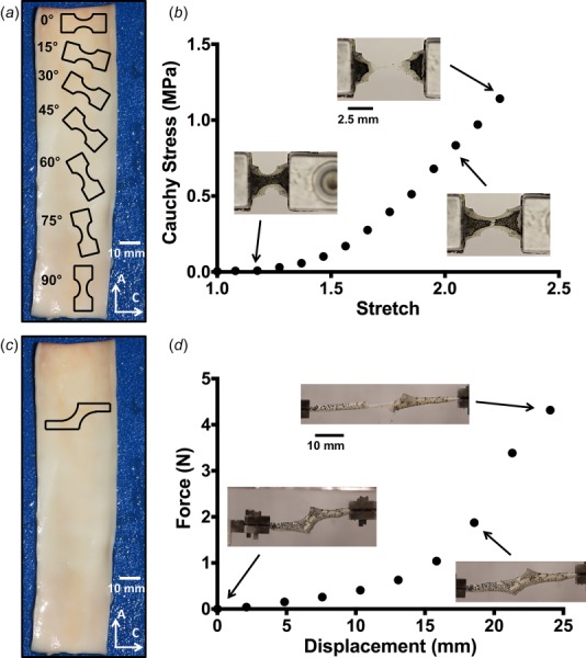
(a) Outlines of dogbone sample geometries are shown along the axial length of the vessel (not drawn to scale). Angles were taken to be relative to the circumferential orientation (0 deg). Scale bar shown in white. (b) A representative stress–stretch curve for one uniaxial sample, with corresponding tissue images during testing. (c) Outline of the shear lap sample geometry (not drawn to scale). (d) A representative force–displacement curve for one shear lap sample. Failure initiated near the overlap region of the sample and propagated across the overlap region (lap across failure).
The measured force was divided by the undeformed cross-sectional area to calculate the first Piola–Kirchhoff stress. Due to speckle adherence issues in the PBS bath, a significant number of uniaxial samples (>40) did not have a usable, distinct speckle pattern for DIC. Strain tracking of selected dogbones (n = 5) showed a maximum error of 10% between the grip stretch and the neck region stretch, so grip stretch was used to convert first Piola–Kirchhoff stresses into Cauchy stresses under the assumption of tissue incompressibility. To validate this method, Cauchy stresses for six samples with usable speckle patterns from one sample angle were calculated based on neck stretch obtained via DIC as well as grip stretch. Cauchy stresses calculated with the grip stretch were within 10% of the stresses calculated with the neck stretch throughout the entire loading curve, and some samples exhibited even as low as 1–2% error throughout the entire loading curve. Statistical analyses (one-way ANOVA and Tukey's multiple comparisons) of failure stresses were performed using GraphPad Prism 6.
2.1.2. Uniaxial Shear Lap Samples.
Shear lap samples were prepared (n = 7 from two porcine aortas) with sample arms oriented in the circumferential direction (Fig. 1(c)). Samples were approximately 35 mm long with an arm width of 3 mm. The overlap region was approximately 5 mm wide at the largest point. The sample geometry was selected due to the large amount of shear that would be imposed in the overlap region of the sample during mechanical testing (cf. Refs. [40] and [41]), yielding a challenging problem for failure predictors.
Samples underwent the same procedure as specified for the uniaxial dog-bones regarding tissue dissection, storage, photographing, and speckling. Shear lap samples were clamped in custom grips, submerged in a 1× PBS bath at room temperature, and pulled in strain-to-failure experiments on a uniaxial testing machine (MTS, Eden Prairie, MN) at a rate of 3 mm/min. Forces were recorded by a static 10 N load cell. The displacement at the onset of failure was determined by correlating the sample video time with the recorded data.
Area fraction of the smaller remaining piece postfailure was calculated using an image of the sample immediately prior to total failure. A crack propagation line was selected for each experimental sample by connecting the start and end points of the crack. Samples were then manually outlined, and the pixel area was calculated for the entire sample and the two pieces on both sides of the crack propagation line. A pixel area average from five manual outlines was used for each piece. Area fraction was calculated as the pixel area of the smaller torn piece divided by the total pixel area of the sample.
The crack propagation angle was calculated in the undeformed domain for each shear lap sample. The line of crack propagation on the image prior to total failure was projected back to the undeformed domain using the deformation gradient (obtained by strain tracking methods described earlier) for an element along the crack propagation line. The crack propagation angle was then calculated between the crack propagation line in the undeformed domain and the horizontal direction.
2.2. Failure Criteria.
The von Mises failure criterion takes the form
| (1) |
where are the normal Cauchy stresses with respect to the coordinate directions. In the case of uniaxial extension (in the 11 direction)
| (2) |
| (3) |
which reduces the von Mises failure criterion to the form
| (4) |
When reaches the failure threshold, , failure is predicted. As the choice of uniaxial yield stress for the von Mises failure criterion is ambiguous, three cases were explored, where the yield stress was equal to (1) the overall average uniaxial failure stress, (2) the average uniaxial circumferential failure stress, and (3) the average uniaxial axial failure stress.
The Tsai–Hill model for a uniaxial test takes the form [26]
| (5) |
where , , and are constants representing the material behavior. Specifically, is the ultimate strength of the material in the principal material direction (direction of highest material strength, typically that of fiber orientation), is the ultimate strength of the material in the transverse direction, and accounts for the shear strength of the material. For in-plane artery tests, the preferred principal material direction was assumed to be the circumferential, and the transverse direction was taken to be the axial, since uniaxial testing shows higher circumferential failure stresses compared to axial [42–44]. Therefore, in Eq. (5), θ was defined to be the counterclockwise sample angle relative to the circumferential direction, was the circumferential (0 deg) failure stress, was the axial (90 deg) failure stress, was the shear stress, and was the failure stress in uniaxial extension at a given sample angle. When θ = 0 deg, the condition reduces to > , and when θ = 90 deg, the condition reduces to > . The three constants , , and were fit to the experimental data.
2.3. Finite Element Modeling.
Finite element models were constructed in FEBio [45] to simulate the shear lap experiments. Each undeformed shear lap sample geometry (n = 7) was reconstructed based on the image taken during experimental testing. A uniform thickness was applied to each sample to match its measured thickness (2.07 ± 0.28 mm, mean ± SD). Geometries were meshed in abaqus with approximately 6000 brick elements.
Sample meshes were imported into FEBio for finite element analysis. The tissue was specified as a volume-conserving uncoupled solid mixture consisting of a Neo-Hookean component given by the strain-energy density function
| (6) |
where is the Neo-Hookean material coefficient, is the first strain invariant of the deviatoric right Cauchy–Green tensor, is the bulk modulus, and is the determinant of the deformation gradient tensor. There was also one fiber family, oriented in the circumferential direction, specified by the strain-energy density function
| (7) |
where is the fiber modulus, is the exponential coefficient, is the power of the exponential, and is the square of the fiber stretch. was set to 2, and , , and were left as fitting parameters based on the prefailure behavior of the tissue during the experiment. The bulk modulus, , was set to one thousand times the Neo-Hookean material coefficient () to ensure that the model was nearly incompressible. The fiber family also had a bulk modulus, which was set to one thousand time the fiber modulus () to ensure incompressibility. Incompressibility was satisfied within 1–7% when the stress reached its maximum. One fiber family, as opposed to multiple, was used to create a constitutive model that captured the experimental behavior with minimal fitting parameters.
To perform each simulation, boundary conditions were applied to the fixed and moving faces of the sample mesh to match the experiment. The nodes on the fixed face were given a zero-displacement boundary condition in all directions, while the nodes on the moving face were given a zero-displacement boundary condition in the vertical and out of plane directions (Fig. 2). Prescribed nodal displacements, based on experimental displacements, were applied to the moving face.
Fig. 2.
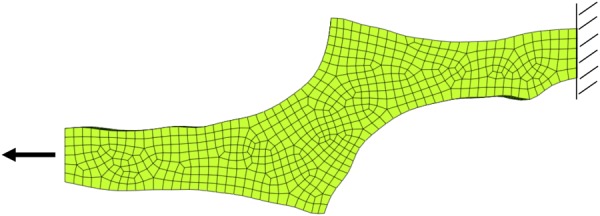
Finite element mesh for one shear lap sample with applied boundary conditions. The nodes on the right face were fixed in all directions, while the nodes on the left face were fixed in the vertical and out of plane directions, and given prescribed displacements based on the experiment.
The material fitting parameters (, , and ) were optimized to fit the experimental loads for each sample by a customized routine utilizing a modified version of the Matlab fminsearch function to minimize the squared error between the simulation and experimental loads (described fully in Ref. [12]). The reaction forces on the moving face were output from the simulation and compared to the experimental loads at ten specified displacements. Comparing the force output from the simulation to the prefailure experimental forces ensured a proper material description. On average, R2 = 0.99 for the seven shear lap samples, with the worst fit having R2 = 0.97. Optimization was performed on one core at the University of Minnesota Supercomputing Institute.
2.4. Two-Dimensional Failure Propagation Simulations.
To compare the predictive capabilities of the von Mises and Tsai–Hill criteria, 2D failure calculations for the shear lap samples were performed in a modified version of the ArcSim thin sheet dynamics simulator [46]. The deforming sample geometry was modeled as a triangle mesh in two dimensions, with elastic forces computed using linear finite elements. The constitutive model (same as above) was adapted to triangular elements by treating them as constant strain prisms with zero out-of-plane shear. Imposing the assumptions of incompressibility and zero out-of-plane normal stress, then determined the deformed thickness and the in-plane stress. Rayleigh damping proportional to the tangential stiffness matrix was added.
In order to resolve regions undergoing failure, the finite-element mesh was dynamically refined during the course of the simulation using the algorithm of Narain et al. [47]. Refinement was driven solely by the value of the failure criterion so that regions close to failure were refined to maximum resolution (a target edge length of 0.05 mm). Failure propagation was computed using the substepping algorithm described by Pfaff et al. [48] that alternated between two steps: (i) splitting elements that reached the failure threshold and (ii) recomputing stresses in the neighborhood using a virtual time step. The substepping algorithm was modified to delete elements undergoing failure, as computing accurate split directions for arbitrary failure criteria proved difficult. The mass loss caused by element deletion was negligible because adaptive refinement ensured extremely small elements near the failure location.
Area fraction was determined for each failure criterion by calculating the mesh area on both sides of the fully failed sample. As in the experimental shear lap samples, area fraction was taken as the area of the smaller torn side over the total area of the sample. Crack propagation angle was calculated for both failure criteria on each sample in the undeformed domain (Figs. 8(c) and 8(d)). A line of crack propagation was created by connecting the two points of crack initiation and total crack failure, and the angle between that line and the horizontal direction determined the crack propagation angle.
Fig. 8.
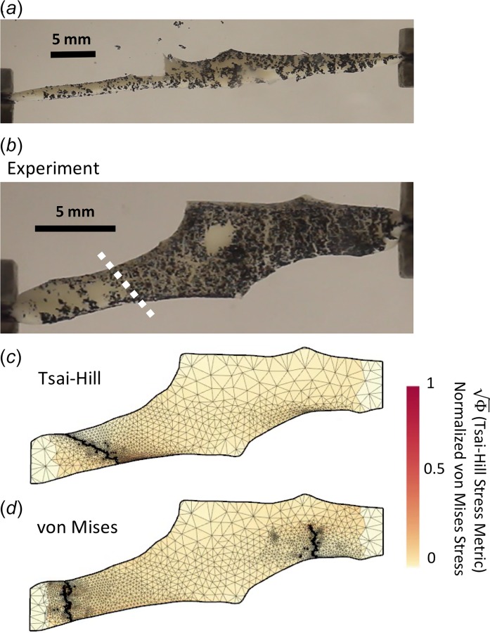
(a) One experimental sample immediately prior to total failure. (b) Sample in the undeformed domain. White dotted line indicates calculated crack propagation location and direction in undeformed domain. Lap arm failure occurred in the experimental sample. (c) and (d) Typical failure comparison between the Tsai–Hill and von Mises failure criteria in the undeformed domain. The Tsai–Hill failure criterion predicted lap arm failure, while the von Mises failure criterion predicted arm failure.
2.5. Failure Calculations in 2D Simulations.
The von Mises stress was calculated for each element and normalized by the von Mises yield stress, , based on the values obtained from experimental testing. Three values were considered when assessing failure with the von Mises failure criterion:
, the mean failure stress in the circumferential direction
, the mean failure stress in the axial direction
, the overall average failure stress based on the mean failure stresses at each sample angle
By normalizing the von Mises stress to each one of these values, failure was considered when the normalized stress in any element reached 1.
In order to evaluate the Tsai–Hill failure criterion, a modified form of Eq. (5) was used [26], in which a failure metric was defined
| (8) |
where , , and are the same as previously stated, and , , and are the stresses in the primary fiber, transverse, and shear directions, respectively. When reached 1, failure was predicted. The model fiber family was oriented in the one direction (circumferential) in the undeformed tissue (i.e., the unit fiber vector points in the horizontal direction). Based on the deformation of each element during the simulation, however, the fiber direction changed. Thus, to calculate the Tsai–Hill failure metric, the Cauchy stress tensor was double-contracted with the affinely rotated unit vectors to calculate , , and . Specifically
| (9) |
| (10) |
where is the primary fiber direction in the undeformed domain, is the transverse direction in the undeformed domain, is the deformation gradient of the element, and , are the primary fiber and transverse directions in the deformed domain, respectively. Therefore, the stress calculations were as follows:
| (11) |
| (12) |
| (13) |
where is the Cauchy stress for each element, calculated by ArcSim. Based on Eq. (8), failure was predicted when the value of in any element reached 1.
3. Results
Experimental testing (n > 9 for each dogbone orientation angle) showed that the largest failure stress occurred in the circumferentially aligned tests (0 deg) at 2.67 ± 0.67 MPa (mean ± 95% confidence interval (CI)), as expected based on previous studies [40,42]. A decrease in failure stress was seen with increasing sample angle to the fully axially aligned case (90 deg) at 1.46 ± 0.59 MPa (Fig. 3). The smallest failure stress was seen in the 75 deg case at 1.41 ± 0.51 MPa, but that value was not significantly lower than the failure stress at 90 deg. A one-way ANOVA showed that the effect of sample angle change on the failure stress was highly significant (p = 0.0003), and a Tukey honest significant difference comparison showed a significant difference between the 0 deg and 90 deg alignment cases (p = 0.01).
Fig. 3.
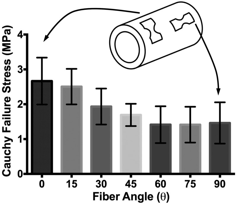
Failure stresses at each sample angle (n > 9 for each angle). ANOVA showed that change in sample angle had a statistically significant effect on failure stress (p = 0.0003). Error bars show 95%CI's.
The von Mises failure criterion did not fit the experimental data well, as the von Mises stress reduces to a single value in the uniaxial case (Eq. (4)). Although the 95% confidence interval range encompassed most of the failure stresses when using 1.87 MPa (Fig. 4(a)), the von Mises criterion could not capture the anisotropic response of the tissue. The data were also not fit when using both 2.67 MPa and 1.46 MPa. The Tsai–Hill model (Eq. (5)), in contrast, showed an excellent fit to the experimental data (R2 = 0.986, Fig. 4(b)). Fitting the model provided = 2.71 ± 0.19 MPa (mean ± 95%CI), = 1.40 ± 0.14 MPa, and = 1.04 ± 0.12 MPa.
Fig. 4.
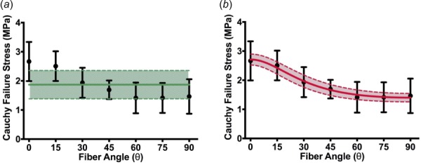
Experiment (points) and failure criteria fits. (a) The von Mises failure criterion (solid green line, 95%CI shaded) fit to the mean peak stresses does not capture the anisotropic response of the tissue. (b) Tsai–Hill maximum-work theory model (solid line, 95%CI shaded). Black error bars indicate 95%CI's on experimental points.
The shear lap samples (n = 7) all exhibited nonlinear behavior until failure (Fig. 1(d)). Digital image correlation showed a large amount of shear strain (∼40%) in the overlap region of the sample (Fig. 5). The onset of tissue failure was calculated to occur at an average displacement of 19.73 ± 1.03 mm (mean ± 95%CI) and load of 3.14 ± 0.22 N, and the total failure of the tissue occurred at an average displacement of 21.53 ± 0.89 mm and load of 3.77 ± 0.33 N. Experimental shear lap samples failed in two different manners: (1) failure began on the arm near the overlap region and propagated into the overlap region of the sample until the sample failed (deemed “lap across” failure, Fig. 6(b)) and (2) failure began on the arm near the overlap region of the sample and propagated toward the overlap region, but ultimately the arm ripped off and failure did not occur in the overlap region (“lap arm” failure, Fig. 8(a)). Four experimental samples experienced lap across failure, while three samples experienced lap arm failure. The crack propagation angle was calculated to be 28.13 deg ± 9.13 deg (mean ± 95%CI) relative to horizontal (Fig. 9), and the area fraction was calculated as 0.33 ± 0.52 (mean ± 95%CI, Fig. 7).
Fig. 5.
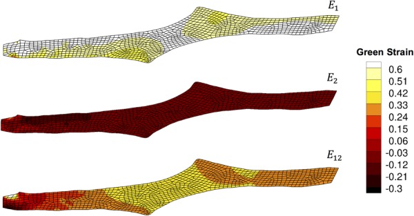
Strain tracking results from one shear lap sample. Large shear strains (∼40%) were exhibited in the overlap region of the sample.
Fig. 6.
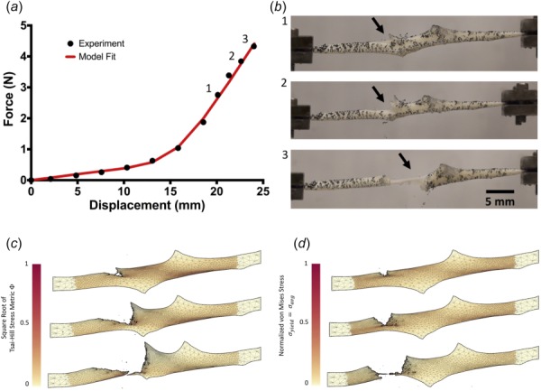
(a) Representative force–displacement curve for one shear lap sample (black dots), with a simulation force–displacement curve (red line) using optimized parameters. (b) Failure propagation for one shear lap sample, shown at three different displacements. The onset of failure began near the overlap region of the sample (indicated by the arrow) and propagated across the center (lap across failure). (c) Failure simulation using the Tsai–Hill criterion. Propagation occurred through the overlap region of the sample and eventually tore in the overlap region (lap across failure). (d) Failure simulation using the von Mises criterion, where . Failure propagated across the sample arm and tore the arm off (arm failure). Failure simulations are shown at similar failure points to the experiment but not at the same displacement as the experiment. (See supplementary videos, which are available under the “Supplemental Materials” tab for this paper on the ASME Digital Collection.)
Fig. 9.
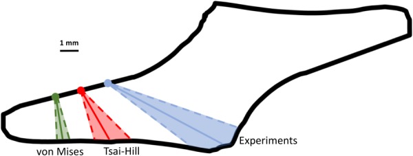
Average failure location (dots) and crack propagation angle (solid line) with 95%CI (dotted lines and shaded region) for experimental samples, Tsai–Hill, and von Mises (avg) failure simulations. Shown in black is the average shear lap sample geometry calculated using radius-based averaging from sample outlines (linear approximation was used for noisy regions of the average sample outline). Samples were rotated (if needed) so that failure occurred in the left arm for comparison purposes.
Fig. 7.
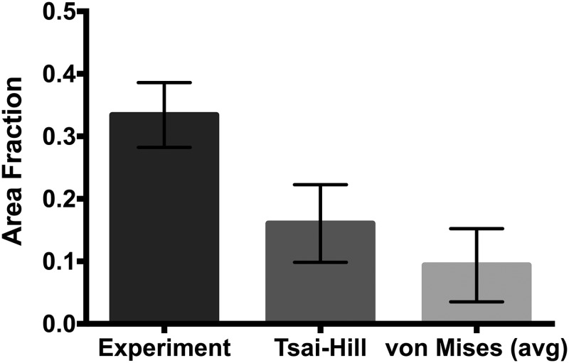
Area fraction for the experimental shear lap samples, along with the Tsai–Hill and von Mises (avg) failure cases. Averages shown with 95%CI bars.
Failure simulations exhibited both types of failure (lap across and lap arm) seen experimentally, along with another, where failure began in the sample arm far away from the overlap region and propagated vertically, only in the arm region (“arm” failure, Figs. 6(d) and 8(d)). The von Mises failure propagation simulations () predicted arm failure for all seven samples. The crack propagation angle was calculated as 80.50 deg ± 6.52 deg (mean ± 95%CI, Fig. 9) and the area fraction was calculated as 0.09 ± 0.06 (Fig. 7). The Tsai–Hill failure propagation simulations predicted one lap across failure, four lap arm failures, and two arm failures. The crack propagation angle was 59.86 deg ± 14.57 deg (mean ± 95%CI, Fig. 9) and the area fraction was 0.16 ± 0.06 (Fig. 7).
Both the von Mises and Tsai–Hill failure criteria severely underpredicted the amount of displacement needed to produce initial failure in the samples. The von Mises failure criterion () predicted the onset of failure at 11.97 ± 0.94 mm (mean ± 95%CI) of displacement, and the Tsai–Hill failure criterion predicted the onset of failure at 11.86 ± 0.85 mm.
4. Discussion
Our results indicate that an isotropic failure criterion, such as the von Mises criterion, is not acceptable when assessing anisotropic tissues. Although the von Mises stress is convenient for visualization of finite element results, one must recognize that the anisotropy of the tissue is not addressed by the von Mises stress. Furthermore, tissues undergo complex loading situations that are unknown a priori, so it is unclear which von Mises yield stress to select for a given tissue. As a result, reporting the von Mises stress risks leading to conclusions that are at best quantitatively inaccurate and at worst misleading or outright wrong when tissue failure is being considered.
The degree of anisotropy in failure mechanics of the aortic wall is highly variable across studies, with different results arising for abdominal versus thoracic aorta and for healthy versus aneurysmal tissue [6,40,42,49–52]. We found a moderate anisotropy (factor of two in the uniaxial failure stress between directions) in our healthy porcine abdominal aortic samples. An increase in sample angle from the circumferential resulted in decreased failure stress.
The Tsai–Hill maximum-work theory provides a single scalar function that considers two perpendicular principal material directions, making it generally applicable to orthotropic lamina [26] such as the porcine abdominal aorta. It is a more robust and potentially a more relevant failure criterion, considering that many tissues, such as arteries, contain anisotropic fibrous networks. Our results show its potential as a tool to predict failure in anisotropic tissues, including the porcine abdominal aorta studied here. Over a range of loading conditions, the Tsai–Hill theory better predicted failure when compared to the von Mises failure criterion. It was able to capture the anisotropic behavior of porcine tissue in uniaxial experiments at different angles and more accurately predict failure type, propagation, and area fraction in 2D failure simulations. Of course, the Tsai–Hill theory is only one simple model that accounts for material anisotropy, and it is likely that a different criterion may work better. For example, many bone (femoral) failure studies have accounted for directional strength by using an anisotropic failure criterion [53–56], namely, the Cowin fracture criterion [57] based on the Tsai–Wu model [58]. Furthermore, the Tsai–Wu model accounts for material strength in multiple directions, which may be more applicable to fibrous tissues with several fiber families, such as arteries.
Other tissues may exhibit regional heterogeneity and fiber anisotropy, in which case a modified approach would be needed. In addition, the Tsai–Hill theory only accounts for two principal directions, but arteries and other fibrous tissues have been characterized by four or more fiber families [59] and/or a continuous fiber distribution [38,60,61], so a more extensive model could be explored. Furthermore, the Tsai–Hill theory is two-dimensional and would require significant experimental effort to expand to three dimensions, as extensive material characterization in three dimensions would be required. Two-dimensional restrictions currently limit the potential application of the Tsai–Hill theory to complex three-dimensional failure problems, such as aortic aneurysms, in which failure mechanisms are clearly three-dimensional [40,62,63].
In our uniaxial experiments, the minimum failure stress occurred at an angle of 75 deg from the preferred direction, but that failure stress was not significantly different from the failure stress at 90 deg (p > 0.5). The Tsai–Hill criterion can support a nonmonotonic failure-angle relation, as is often seen in synthetic fiber composites [26]. Whether the minimum at 75 deg was real or noise, and whether other tissues do or do not exhibit a local minimum in failure stress are questions that merit further exploration.
The assumption of constant failure through the thickness of the shear lap samples and the use of a two-dimensional failure code are questionable and likely incorrect. Furthermore, the constitutive equation is rather simplistic, the optimization only fit the forces on the moving face of the experimental sample, and no strain field data were used to help optimize constitutive parameters [64]. An inadequate constitutive model most likely resulted in an inaccurate stress field, which may have contributed to the incorrect failure prediction results. The use of alternative constitutive models (i.e., the Holzapfel–Gasser–Ogden model [38] or the four-fiber family model [65]) may prove more effective. The underprediction of displacement may be due to the extreme nonlinearity of the exponentials, leading to artificially high stresses as the strains increase, and a constitutive model which incorporates plasticity could potentially address this issue. The material was also treated as perfectly elastic, resulting in brittle failure. Furthermore, the von Mises and Tsai–Hill failure criteria do not address the idea of crack initiation and propagation in their formulation, which may be the main factor contributing to inadequate model predictions. These assumptions are the most likely causes for the limited ability of the models to accurately predict the displacement at the onset of failure, crack initiation, and crack propagation for all experimental samples.
It should also be noted that the use of a particular stress or failure criterion is dependent upon the objectives of a given study. Often, there is sufficient reasoning for using the von Mises stress when analyzing anisotropic tissues, such as comparing different tissue types, where the importance of comparison outweighs the need for accuracy; the von Mises failure criterion captures the failure behavior of porcine abdominal aorta with relatively mild error (Fig. 4(a)), which may meet the needs of a specific study. It is also often the case that extensive material strength data for anisotropic tissues are not readily available. Furthermore, available resources and the complexity of certain problems require computational simplifications, as in the case of large geometries comprised of multiple types of materials, in which case the von Mises stress would be better suited. Even in those cases, however, it is essential to recognize that if the tissue is anisotropic, its failure behavior will surely be anisotropic, and an isotropic failure criterion may be misleading.
Tissue failure is a very complex process, as demonstrated by experimental work [6,66] and microstructural theory [40,62,67]. Accurately characterizing tissue failure requires an adequate understanding of tissue behavior, particularly in relation to directional material strength and failure methods. Ignoring well-known tissue properties that contribute to failure (e.g., the mechanical anisotropy explored here) yields incorrect assessments and ultimately limits the potential use of failure-predicting tools in applications such as patient diagnosis.
Supplementary Material
Acknowledgment
This material is based upon work supported by the National Science Foundation Graduate Research Fellowship Program under Grant No. 00039202 (CEK). Any opinions, findings, and conclusions or recommendations expressed in this material are those of the author(s) and do not necessarily reflect the views of the National Science Foundation. This work was supported by the National Institutes of Health (R01EB005813), and CEK is a recipient of the Richard Pyle Scholar Award from the ARCS Foundation. Tissue was provided by the Visible Heart Laboratory at the University of Minnesota. The authors acknowledge the Minnesota Supercomputing Institute (MSI) at the University of Minnesota for providing resources that contributed to the research results reported within this paper. We also gratefully acknowledge the assistance of Vahhab Zarei and Jacob Solinksy.
Contributor Information
Christopher E. Korenczuk, Department of Biomedical Engineering, , University of Minnesota, , 7-105 Nils Hasselmo Hall, , 312 Church Street SE, , Minneapolis, MN 55455 , e-mail: koren046@umn.edu
Lauren E. Votava, Department of Biomedical Engineering, , University of Minnesota, , Minneapolis, MN 55455 , e-mail: vota0017@umn.edu
Rohit Y. Dhume, Department of Mechanical Engineering, , University of Minnesota, , Minneapolis, MN 55455 , e-mail: dhume001@umn.edu
Shannen B. Kizilski, Department of Mechanical Engineering, , University of Minnesota, , Minneapolis, MN 55455 , e-mail: kizil015@umn.edu
George E. Brown, Department of Computer , Science and Engineering, , University of Minnesota, , Minneapolis, MN 55455 , e-mail: brow2327@umn.edu
Rahul Narain, Department of Computer Science , and Engineering, , University of Minnesota, , Minneapolis, MN 55455 , e-mail: narain@umn.edu.
Victor H. Barocas, Department of Biomedical Engineering, , University of Minnesota, , Minneapolis, MN 55455 , e-mail: baroc001@umn.edu.
References
- [1]. Grosse, I. , Huang, L. , Davis, J. , and Cullinane, D. , 2014, “ A Multi-Level Hierarchical Finite Element Model for Capillary Failure in Soft Tissue,” ASME J. Biomech. Eng., 136(8), p. 081010. 10.1115/1.4027730 [DOI] [PubMed] [Google Scholar]
- [2]. Sanyal, A. , Scheffelin, J. , and Keaveny, T. M. , 2015, “ The Quartic Piecewise-Linear Criterion for the Multiaxial Yield Behavior of Human Trabecular Bone,” ASME J. Biomech. Eng., 137(1), p. 011009. 10.1115/1.4029109 [DOI] [PMC free article] [PubMed] [Google Scholar]
- [3]. Zwahlen, A. , Christen, D. , Ruffoni, D. , Schneider, P. , Schmölz, W. , and Müller, R. , 2015, “ Inverse Finite Element Modeling for Characterization of Local Elastic Properties in Image-Guided Failure Assessment of Human Trabecular Bone,” ASME J. Biomech. Eng., 137(1), p. 11012. 10.1115/1.4028991 [DOI] [PubMed] [Google Scholar]
- [4]. Clouthier, A. L. , Hosseini, H. S. , Maquer, G. , and Zysset, P. K. , 2015, “ Finite Element Analysis Predicts Experimental Failure Patterns in Vertebral Bodies Loaded Via Intervertebral Discs up to Large Deformation,” Med. Eng. Phys., 37(6), pp. 599–604. 10.1016/j.medengphy.2015.03.007 [DOI] [PubMed] [Google Scholar]
- [5]. Holzapfel, G. A. , Sommer, G. , Gasser, C. T. , and Regitnig, P. , 2005, “ Determination of Layer-Specific Mechanical Properties of Human Coronary Arteries With Nonatherosclerotic Intimal Thickening and Related Constitutive Modeling,” Am. J. Physiol. Hear. Circ. Physiol., 289(5), pp. 2048–2058. 10.1152/ajpheart.00934.2004 [DOI] [PubMed] [Google Scholar]
- [6]. Vorp, D. A. , Schiro, B. J. , Ehrlich, M. P. , Juvonen, T. S. , Ergin, M. A. , and Griffith, B. P. , 2003, “ Effect of Aneurysm on the Tensile Strength and Biomechanical Behavior of the Ascending Thoracic Aorta,” Ann. Thorac. Surg., 75(4), pp. 1210–1214. 10.1016/S0003-4975(02)04711-2 [DOI] [PubMed] [Google Scholar]
- [7]. Duprey, A. , Trabelsi, O. , Vola, M. , Favre, J. P. , and Avril, S. , 2016, “ Biaxial Rupture Properties of Ascending Thoracic Aortic Aneurysms,” Acta Biomater., 42, pp. 273–285. 10.1016/j.actbio.2016.06.028 [DOI] [PubMed] [Google Scholar]
- [8]. Luo, Y. , Duprey, A. , Avril, S. , and Lu, J. , 2016, “ Characteristics of Thoracic Aortic Aneurysm Rupture in vitro,” Acta Biomater., 42, pp. 286–295. 10.1016/j.actbio.2016.06.036 [DOI] [PubMed] [Google Scholar]
- [9]. Woo, S. L. , Gomez, M. A. , Seguchi, Y. , Endo, C. M. , and Akeson, W. H. , 1983, “ Measurement of Mechanical Properties of Ligament Substance From a Bone-Ligament-Bone Preparation,” J. Orthop. Res., 1(1), pp. 22–29. 10.1002/jor.1100010104 [DOI] [PubMed] [Google Scholar]
- [10]. Woo, S. L. , Hollis, J. M. , Adams, D. J. , Lyon, R. M. , and Takai, S. , 1991, “ Tensile Properties of the Human Femur-Anterior Cruciate Ligament-Tibia Complex. The Effects of Specimen Age and Orientation,” Am. J. Sports Med., 19(3), pp. 217–225. 10.1177/036354659101900303 [DOI] [PubMed] [Google Scholar]
- [11]. Little, J. S. , and Khalsa, P. S. , 2005, “ Material Properties of the Human Lumbar Facet Joint Capsule,” ASME J. Biomech. Eng., 127(1), pp. 15–24. 10.1115/1.1835348 [DOI] [PMC free article] [PubMed] [Google Scholar]
- [12]. Claeson, A. A. , and Barocas, V. H. , 2017, “ Planar Biaxial Extension of the Lumbar Facet Capsular Ligament Reveals Significant In-Plane Shear Forces,” J. Mech. Behav. Biomed. Mater., 65, pp. 127–136. 10.1016/j.jmbbm.2016.08.019 [DOI] [PMC free article] [PubMed] [Google Scholar]
- [13]. Nicholls, S. P. , Gathereole, L. J. , Keller, A. , and Shah, J. S. , 1983, “ Crimping in Rat Tail Tendon Collagen: Morphology and Transverse Mechanical Anisotropy,” Int. J. Biol. Macromol., 5(5), pp. 283–288. 10.1016/0141-8130(83)90043-0 [DOI] [Google Scholar]
- [14]. Natali, A. N. , Pavan, P. G. , Carniel, E. L. , Lucisano, M. E. , and Taglialavoro, G. , 2005, “ Anisotropic Elasto-Damage Constitutive Model for the Biomechanical Analysis of Tendons,” Med. Eng. Phys., 27(3), pp. 209–214. 10.1016/j.medengphy.2004.10.011 [DOI] [PubMed] [Google Scholar]
- [15]. Takaza, M. , Moerman, K. M. , Gindre, J. , Lyons, G. , and Simms, C. K. , 2012, “ The Anisotropic Mechanical Behaviour of Passive Skeletal Muscle Tissue Subjected to Large Tensile Strain,” J. Mech. Behav. Biomed. Mater., 17, pp. 209–220. 10.1016/j.jmbbm.2012.09.001 [DOI] [PubMed] [Google Scholar]
- [16]. Gennisson, J. L. , Deffieux, T. , Macé, E. , Montaldo, G. , Fink, M. , and Tanter, M. , 2010, “ Viscoelastic and Anisotropic Mechanical Properties of In Vivo Muscle Tissue Assessed by Supersonic Shear Imaging,” Ultrasound Med. Biol., 36(5), pp. 789–801. 10.1016/j.ultrasmedbio.2010.02.013 [DOI] [PubMed] [Google Scholar]
- [17]. Duthon, V. B. , Barea, C. , Abrassart, S. , Fasel, J. H. , Fritschy, D. , and Ménétrey, J. , 2006, “ Anatomy of the Anterior Cruciate Ligament,” Knee Surg., Sports Traumatol. Arthroscopy, 14(3), pp. 204–213. 10.1007/s00167-005-0679-9 [DOI] [PubMed] [Google Scholar]
- [18]. Volokh, K. Y. , 2011, “ Modeling Failure of Soft Anisotropic Materials With Application to Arteries,” J. Mech. Behav. Biomed. Mater., 4(8), pp. 1582–1594. 10.1016/j.jmbbm.2011.01.002 [DOI] [PubMed] [Google Scholar]
- [19]. Karimi, A. , Navidbakhsh, M. , and Razaghi, R. , 2014, “ Plaque and Arterial Vulnerability Investigation in a Three-Layer Atherosclerotic Human Coronary Artery Using Computational Fluid-Structure Interaction Method,” J. Appl. Phys., 116(6), p. 064701. 10.1063/1.4893368 [DOI] [Google Scholar]
- [20]. Wood, S. A. , Strait, D. S. , Dumont, E. R. , Ross, C. F. , and Grosse, I. R. , 2011, “ The Effects of Modeling Simplifications on Craniofacial Finite Element Models: The Alveoli (Tooth Sockets) and Periodontal Ligaments,” J. Biomech., 44(10), pp. 1831–1838. 10.1016/j.jbiomech.2011.03.022 [DOI] [PubMed] [Google Scholar]
- [21]. Phillippi, J. A. , Pasta, S. , and Vorp, D. A. , 2011, “ Biomechanics and Pathobiology of Aortic Aneurysms,” Biomechanics and Mechanobiology of Aneurysms, Springer, Berlin, pp. 67–118. [Google Scholar]
- [22]. Nathan, D. P. , Xu, C. , Gorman, J. H. , Fairman, R. M. , Bavaria, J. E. , Gorman, R. C. , Chandran, K. B. , and Jackson, B. M. , 2011, “ Pathogenesis of Acute Aortic Dissection: A Finite Element Stress Analysis,” Ann. Thorac. Surg., 91(2), pp. 458–463. 10.1016/j.athoracsur.2010.10.042 [DOI] [PubMed] [Google Scholar]
- [23]. Humphrey, J. D. , and Holzapfel, G. A. , 2012, “ Mechanics, Mechanobiology, and Modeling of Human Abdominal Aorta and Aneurysms,” J. Biomech., 45(5), pp. 805–814. 10.1016/j.jbiomech.2011.11.021 [DOI] [PMC free article] [PubMed] [Google Scholar]
- [24]. Hwang, E. , Hughes, R. E. , Palmer, M. L. , and Carpenter, J. E. , 2015, “ Effects of Biceps Tension on the Torn Superior Glenoid Labrum,” J. Orthop. Res., 33(10), pp. 1545–1551. 10.1002/jor.22888 [DOI] [PubMed] [Google Scholar]
- [25]. Quental, C. , Folgado, J. , Monteiro, J. , and Sarmento, M. , 2016, “ Full-Thickness Tears of the Supraspinatus Tendon: A Three-Dimensional Finite Element Analysis,” J. Biomech., 49(16), pp. 3962–3970. 10.1016/j.jbiomech.2016.11.049 [DOI] [PubMed] [Google Scholar]
- [26]. Agarwal, B. , Broutman, L. , and Chandrashekhara, K. , 2006, Analysis and Performance of Fiber Composites, Wiley, Hoboken, NJ. [Google Scholar]
- [27]. Matzenmiller, A. , Lubliner, J. , and Taylor, R. L. , 1995, “ A Constitutive Model for Anisotropic Damage in Fiber-Composites,” Mech. Mater., 20(2), pp. 125–152. 10.1016/0167-6636(94)00053-0 [DOI] [Google Scholar]
- [28]. Derrien, K. , Fitoussi, J. , Guo, G. , and Baptiste, D. , 2000, “ Prediction of the Effective Damage Properties and Failure Properties of Nonlinear Anisotropic Discontinuous Reinforced Composites,” Comput. Methods Appl. Mech. Eng., 185(2–4), pp. 93–107. 10.1016/S0045-7825(99)00253-4 [DOI] [Google Scholar]
- [29]. Nuismer, R. J. , and Whitney, J. M. , 1975, “ Uniaxial Failure of Composite Laminates Containing Stress Concentrations,” Fract. Mech. Compos., 593, pp. 117–142. 10.1520/STP34795S [DOI] [Google Scholar]
- [30]. Fuchs, C. , Bhattacharyya, D. , and Fakirov, S. , 2006, “ Microfibril Reinforced Polymer–Polymer Composites: Application of Tsai-Hill Equation to PP/PET Composites,” Compos. Sci. Technol., 66(16), pp. 3161–3171. 10.1016/j.compscitech.2005.02.023 [DOI] [Google Scholar]
- [31]. Aktas, A. , and Karakuzu, R. , 1999, “ Failure Analysis of Two-Dimensional Carbon-Epoxy Composite Plate Pinned Joint,” Mech. Compos. Mater. Struct., 6(4), pp. 347–361. 10.1080/107594199305502 [DOI] [Google Scholar]
- [32]. Tsai, S. W. , 1968, Fundamental Aspects of Fiber Reinforced Plastic Composites, Interscience, New York. [Google Scholar]
- [33]. Hill, R. , 1950, The Mathematical Theory of Plasticity, Oxford University Press, New York. [Google Scholar]
- [34]. Arola, D. , and Ramulu, M. , 1997, “ Orthogonal Cutting of Fiber-Reinforced Composites: A Finite Element Analysis,” Int. J. Mech. Sci., 39(5), pp. 597–613. 10.1016/S0020-7403(96)00061-6 [DOI] [Google Scholar]
- [35]. Liu, J. Y. , 2007, “ Analysis of Off-Axis Tension Test of Wood Specimens,” Wood Fiber Sci., 34(2), pp. 205–211.https://wfs.swst.org/index.php/wfs/article/view/1905/1905 [Google Scholar]
- [36]. Woo, K. , and Whitcomb, J. , 1996, “ Three-Dimensional Failure Analysis of Plain Weave Textile Composites Using a Global/Local Finite Element Method,” J. Compos. Mater., 30(9), pp. 984–1003. 10.1177/002199839603000902 [DOI] [Google Scholar]
- [37]. Wagenseil, J. , and Mecham, R. , 2009, “ Vascular Extracellular Matrix and Arterial Mechanics,” Am. Physiol. Soc., 89(3), pp. 957–989. 10.1152/physrev.00041.2008 [DOI] [PMC free article] [PubMed] [Google Scholar]
- [38]. Gasser, T. C. , Ogden, R. W. , and Holzapfel, G. A. , 2006, “ Hyperelastic Modelling of Arterial Layers With Distributed Collagen Fibre Orientations,” J. R. Soc., Interface, 3(6), pp. 15–35. 10.1098/rsif.2005.0073 [DOI] [PMC free article] [PubMed] [Google Scholar]
- [39]. Raghupathy, R. , Witzenburg, C. , Lake, S. P. , Sander, E. A. , and Barocas, V. H. , 2011, “ Identification of Regional Mechanical Anisotropy in Soft Tissue Analogs,” ASME J. Biomech. Eng., 133(9), p. 91011. 10.1115/1.4005170 [DOI] [PMC free article] [PubMed] [Google Scholar]
- [40]. Witzenburg, C. M. , Dhume, R. Y. , Shah, S. B. , Korenczuk, C. E. , Wagner, H. P. , Alford, P. W. , and Barocas, V. H. , 2017, “ Failure of the Porcine Ascending Aorta: Multidirectional Experiments and a Unifying Microstructural Model,” ASME J. Biomech. Eng., 139(3), p. 31005. 10.1115/1.4035264 [DOI] [PMC free article] [PubMed] [Google Scholar]
- [41]. Gregory, D. E. , Veldhuis, J. H. , Horst, C. , Brodland, G. W. , and Callaghan, J. P. , 2011, “ Novel Lap Test Determines the Mechanics of Delamination Between Annular Lamellae of the Intervertebral Disc,” J. Biomech., 44(1), pp. 97–102. 10.1016/j.jbiomech.2010.08.031 [DOI] [PubMed] [Google Scholar]
- [42]. García-Herrera, C. M. , Atienza, J. M. , Rojo, F. J. , Claes, E. , Guinea, G. V. , Celentano, D. J. , García-Montero, C. , and Burgos, R. L. , 2012, “ Mechanical Behaviour and Rupture of Normal and Pathological Human Ascending Aortic Wall,” Med. Biol. Eng. Comput., 50(6), pp. 559–566. 10.1007/s11517-012-0876-x [DOI] [PubMed] [Google Scholar]
- [43]. Iliopoulos, D. C. , Deveja, R. P. , Kritharis, E. P. , Perrea, D. , Sionis, G. D. , Toutouzas, K. , Stefanadis, C. , and Sokolis, D. P. , 2009, “ Regional and Directional Variations in the Mechanical Properties of Ascending Thoracic Aortic Aneurysms,” Med. Eng. Phys., 31(1), pp. 1–9. 10.1016/j.medengphy.2008.03.002 [DOI] [PubMed] [Google Scholar]
- [44]. Sokolis, D. P. , Kritharis, E. P. , and Iliopoulos, D. C. , 2012, “ Effect of Layer Heterogeneity on the Biomechanical Properties of Ascending Thoracic Aortic Aneurysms,” Med. Biol. Eng. Comput., 50(12), pp. 1227–1237. 10.1007/s11517-012-0949-x [DOI] [PubMed] [Google Scholar]
- [45]. Maas, S. A. , Ellis, B. J. , Ateshian, G. A. , and Weiss, J. A. , 2012, “ FEBio: Finite Elements for Biomechanics,” ASME J. Biomech. Eng., 134(1), p. 11005. 10.1115/1.4005694 [DOI] [PMC free article] [PubMed] [Google Scholar]
- [46]. Narain, R. , Samii, A. , Pfaff, T. , and O'Brien, J. , 2014, “ ARCSim: Adaptive Refining and Coarsening Simulator,” University of California–Berkley, Berkley, CA, accessed Oct. 1, 2016, http://graphics.berkeley.edu/resources/ARCSim/
- [47]. Narain, R. , Samii, A. , and O'Brien, J. F. , 2012, “ Adaptive Anisotropic Remeshing for Cloth Simulation,” ACM Trans. Graphics, 31(6), p. 147. 10.1145/2366145.2366171 [DOI] [Google Scholar]
- [48]. Pfaff, T. , Narain, R. , De Joya, J. M. , and O'Brien, J. F. , 2014, “ Adaptive Tearing and Cracking of Thin Sheets,” ACM Trans. Graphics, 33(4), pp. 1–9. 10.1145/2601097.2601132 [DOI] [Google Scholar]
- [49]. Mohan, D. , and Melvin, J. W. , 1983, “ Failure Properties of Passive Human Aortic Tissue. II—Biaxial Tension Tests,” J. Biomech., 16(1), pp. 31–44. 10.1016/0021-9290(83)90044-1 [DOI] [PubMed] [Google Scholar]
- [50]. Kim, J.-H. , Avril, S. , Duprey, A. , and Favre, J.-P. , 2012, “ Experimental Characterization of Rupture in Human Aortic Aneurysms Using a Full-Field Measurement Technique,” Biomech. Model. Mechanobiol., 11(6), pp. 841–853. 10.1007/s10237-011-0356-5 [DOI] [PubMed] [Google Scholar]
- [51]. Teng, Z. , Feng, J. , Zhang, Y. , Huang, Y. , Sutcliffe, M. P. F. , Brown, A. J. , Jing, Z. , Gillard, J. H. , and Lu, Q. , 2015, “ Layer- and Direction-Specific Material Properties, Extreme Extensibility and Ultimate Material Strength of Human Abdominal Aorta and Aneurysm: A Uniaxial Extension Study,” Ann. Biomed. Eng., 43(11), pp. 2745–2759. 10.1007/s10439-015-1323-6 [DOI] [PMC free article] [PubMed] [Google Scholar]
- [52]. Shah, S. , Witzenburg, C. , Hadi, M. F. , Wagner, H. , Goodrich, J. , Alford, P. , and Barocas, V. H. , 2014, “ Prefailure and Failure Mechanics of the Porcine Ascending Thoracic Aorta: Experiments and a Multiscale Model,” ASME J. Biomech. Eng., 136(2), pp. 4–10. 10.1115/1.4026443 [DOI] [PMC free article] [PubMed] [Google Scholar]
- [53]. Gómez-Benito, M. J. , García-Aznar, J. M. , and Doblaré, M. , 2005, “ Finite Element Prediction of Proximal Femoral Fracture Patterns Under Different Loads,” ASME J. Biomech. Eng., 127(1), pp. 9–14. 10.1115/1.1835347 [DOI] [PubMed] [Google Scholar]
- [54]. Pietruszczak, S. , Inglis, D. , and Pande, G. N. , 1999, “ A Fabric-Dependent Fracture Criterion for Bone,” J. Biomech., 32(10), pp. 1071–1079. 10.1016/S0021-9290(99)00096-2 [DOI] [PubMed] [Google Scholar]
- [55]. Cezayirlioglu, H. , Bahniuk, E. , Davy, D. T. , and Heiple, K. G. , 1985, “ Anisotropic Yield Behavior of Bone Under Combined Axial Force and Torque,” J. Biomech., 18(1), pp. 61–69. 10.1016/0021-9290(85)90045-4 [DOI] [PubMed] [Google Scholar]
- [56]. Feerick, E. M. , Liu, X. C. , and McGarry, P. , 2013, “ Anisotropic Mode-Dependent Damage of Cortical Bone Using the Extended Finite Element Method (XFEM),” J. Mech. Behav. Biomed. Mater., 20, pp. 77–89. 10.1016/j.jmbbm.2012.12.004 [DOI] [PubMed] [Google Scholar]
- [57]. Cowin, S. C. , 1986, “ Fabric Dependence of an Anisotropic Strength Criterion,” Mech. Mater., 5(3), pp. 251–260. 10.1016/0167-6636(86)90022-0 [DOI] [Google Scholar]
- [58]. Tsai, S. W. , and Wu, E. M. , 1971, “ A General Theory of Strength for Anisotropic Materials,” J. Compos. Mater., 5(1), pp. 58–80. 10.1177/002199837100500106 [DOI] [Google Scholar]
- [59]. Humphrey, J. D. , and Yin, F. C. P. , 1987, “ On Constitutive Relations and Finite Deformations of Passive Cardiac Tissue—I. A Pseudostrain-Energy Function,” ASME J. Biomech. Eng., 109(4), pp. 298–304. 10.1115/1.3138684 [DOI] [PubMed] [Google Scholar]
- [60]. Cortes, D. H. , Lake, S. P. , Kadlowec, J. A. , Soslowsky, L. J. , and Elliott, D. M. , 2010, “ Characterizing the Mechanical Contribution of Fiber Angular Distribution in Connective Tissue: Comparison of Two Modeling Approaches,” Biomech. Model. Mechanobiol., 9(5), pp. 651–658. 10.1007/s10237-010-0194-x [DOI] [PMC free article] [PubMed] [Google Scholar]
- [61]. Sacks, M. S. , 2003, “ Incorporation of Experimentally-Derived Fiber Orientation Into a Structural Constitutive Model for Planar Collagenous Tissues,” ASME J. Biomech. Eng., 125(2), pp. 280–287. 10.1115/1.1544508 [DOI] [PubMed] [Google Scholar]
- [62]. Pal, S. , Tsamis, A. , Pasta, S. , D'Amore, A. , Gleason, T. G. , Vorp, D. A. , and Maiti, S. , 2014, “ A Mechanistic Model on the Role of ‘Radially-Running’ Collagen Fibers on Dissection Properties of Human Ascending Thoracic Aorta,” J. Biomech., 47(5), pp. 981–988. 10.1016/j.jbiomech.2014.01.005 [DOI] [PMC free article] [PubMed] [Google Scholar]
- [63]. Sommer, G. , Gasser, T. C. , Regitnig, P. , Auer, M. , and Holzapfel, G. A. , 2008, “ Dissection Properties of the Human Aortic Media: An Experimental Study,” ASME J. Biomech. Eng., 130(2), p. 21007. 10.1115/1.2898733 [DOI] [PubMed] [Google Scholar]
- [64]. Nagel, T. M. , Hadi, M. F. , Claeson, A. A. , Nuckley, D. J. , and Barocas, V. H. , 2014, “ Combining Displacement Field and Grip Force Information to Determine Mechanical Properties of Planar Tissue With Complicated Geometry,” ASME J. Biomech. Eng., 136(11), p. 114501. 10.1115/1.4028193 [DOI] [PMC free article] [PubMed] [Google Scholar]
- [65]. Baek, S. , Gleason, R. L. , Rajagopal, K. R. , and Humphrey, J. D. , 2007, “ Theory of Small on Large: Potential Utility in Computations of Fluid–Solid Interactions in Arteries,” Comput. Methods Appl. Mech. Eng., 196(31–32), pp. 3070–3078. 10.1016/j.cma.2006.06.018 [DOI] [Google Scholar]
- [66]. Tong, J. , Cheng, Y. , and Holzapfel, G. A. , 2016, “ Mechanical Assessment of Arterial Dissection in Health and Disease: Advancements and Challenges,” J. Biomech., 49(12), pp. 2366–2373. 10.1016/j.jbiomech.2016.02.009 [DOI] [PubMed] [Google Scholar]
- [67]. Balakhovsky, K. , Jabareen, M. , and Volokh, K. Y. , 2014, “ Modeling Rupture of Growing Aneurysms,” J. Biomech., 47(3), pp. 653–658. 10.1016/j.jbiomech.2013.11.049 [DOI] [PubMed] [Google Scholar]
Associated Data
This section collects any data citations, data availability statements, or supplementary materials included in this article.


