Abstract
We describe two approaches based upon ion “elevator” and “escalator” components that allow moving ions to different levels in structures for lossless ion manipulations (SLIM). Guided by ion motion simulations, we designed elevator and escalator components based upon ion current measurements providing essentially lossless transmission in multilevel designs. The ion elevator design allowed ions to efficiently bridge a 4 mm gap between levels. The component was integrated in a SLIM and coupled to a QTOF mass spectrometer using an ion funnel interface to evaluate the m/z range transmitted as compared to transmission within a level (e.g., in a linear section). The analysis of singly charged ions of m/z 600–2700 produced similar mass spectra for both elevator and straight (linear motion) components. In the ion escalator design, traveling waves (TW) were utilized to transport ions efficiently between two SLIM levels. Ion current measurements and ion mobility (IM) spectrometry analysis illustrated that ions can be transported between TW-SLIM levels with no significant loss of either ions or IM resolution. These developments provide a path for the development of multilevel designs providing, e.g., much longer IM path lengths, more compact designs, and the implementation of much more complex SLIM devices in which, e.g., different levels may operate at different temperatures or with different gases.
Graphical abstract

In order to enhance ion mobility (IM) separations as well as enable other and more complex combinations of ion manipulations in the gas phase, our laboratory has recently introduced structures for lossless ion manipulations (SLIM).1–3 SLIM are constructed from arrays of electrodes patterned on printed circuit boards and exploiting our understanding of the combined actions of the applied dc and rf fields and their interactions with ions as well as the ability to model and simulate these interactions.4,5 Our initial SLIM used electric fields created by the application of appropriate potentials to arrays of dc “guard” electrodes in addition to rf and dc potentials applied to arrays of “rung” electrodes (located between the guard electrodes) on the two planar surfaces. The opposing polarity of rf waveforms applied to adjacent rung electrodes creates an effective potential that prevents ion loss to the surfaces.5–7 The resulting fields both confine and drive ions in the field-generated “ion conduits” between the two flat and closely spaced surfaces.2,3,8 A SLIM drift IM module was initially implemented using a static dc voltage gradient coapplied with the rf to the rung electrodes to drive the ion motion and provided good performance, along with other ion manipulation capabilities such as the ability to select, trap, accumulate, and fragment selected species after IM separation.1,2,8,9 We then developed traveling wave SLIM (TW-SLIM) that provide greater flexibility for ion manipulations and IM separations and avoiding the implicit limitations on maximum path length due to voltage constraints imposed by a uniform static field in conventional drift tubes.10–12 The rung electrodes in the TW-SLIM used long rf electrodes separated by segmented dc electrodes. TW-SLIM IM modules were found to have similar capabilities to the uniform-field SLIM modules10–14 and allowed for extended path lengths, thus achieving higher IM resolutions in relatively compact devices.10–14 TW-SLIM modules were also demonstrated to enable the trapping of much larger ion populations and the ability to perform IM peak “compression”, of great utility for reversing peak diffusional growth and loss of peak intensities in extended ultrahigh resolution IM separations.14,15
The ability to efficiently move ions between different levels of multilevel SLIM devices would greatly expand the range of potential applications and enable more complex ion manipulations. For instance, different ion manipulations such as those involving ion–ion, photon–ion, or ion–neutral interactions could be performed in separate levels. SLIM modules and devices reported so far have enabled manipulation of ions confined to the two dimensions defined by one SLIM level. In this manuscript, two new component concepts, the SLIM “elevator” and “escalator”, for transporting ions between different levels of SLIM devices are reported. They have been initially evaluated for ion transmission efficiency, effective m/z range transmitted, and for the potential impact on IM resolution achieved in the larger SLIM module in comparison with planar designs, i.e., where no elevator or escalator is used. These developments provide a foundation for the development of much more complex multilevel designs providing much longer IM path lengths, more compact designs, and the implementation of SLIM in which different levels operate at different temperatures or with different gases.
EXPERIMENTAL SETUP
Experiments were performed in a home-built platform that combined an ion source, the SLIM, and a quadrupole time-of-flight MS for detection (Figure 1). Ions were formed by electrospray ionization (ESI) of melittin (10 μM in 10% methanol/90% H2O by volume acidified with 0.1% formic acid) or Agilent low concentration ESI tuning mix (Agilent, Santa Clara, CA) infused into an etched fused silica emitter (20 μm i.d.) at a flow rate of 300 nL/min. Ions were sampled by a 500 μm i.d. stainless steel inlet capillary heated to 120 °C. After exiting the heated capillary, ions were focused in the ion funnel trap (rf 1.3 MHz and ~160 Vp-p) at 3.95 Torr.8,16,17 The ion funnel trap was constructed utilizing printed-circuit boards.18 For the elevator module, the ion funnel trap was operated in the continuous mode (i.e., no trapping) but in the escalator mode ions were also trapped for 10 ms and gated as 324 μs pulses. The center axis of the inlet capillary was offset from the ion funnel center axis by ~6 mm to minimize the contamination of SLIM by partially desolvated charged droplets. Ions exiting the ion funnel were transmitted to the SLIM by a short quadrupole (Q00, 6.4 mm o.d., 17.3 mm long, and 2.8 mm inscribed radius) operating in an “rf-only” mode (1 MHz and 200 Vp-p). Ions exiting Q00 were transmitted to a SLIM configured to direct ions to either a linear path (blue in Figure 1) or the elevator (red in Figure 1). Details for the SLIM elevator and TW-SLIM escalator are given below. Ions exiting the SLIM enter an 18 cm long rear ion funnel operating at an rf of 180 Vp-p and 1 MHz and having an entrance orifice of 25.4 mm i.d. and exit of 2.5 mm i.d. The pressure in the chamber housing the Q00, SLIM, and rear ion funnel was maintained slightly higher, using high-purity nitrogen gas, than the pressure in the ion funnel trap to minimize neutrals introduction from the source.3 Ions exit the rear ion funnel into a differentially pumped rf-only quadrupole (Q0, 6.35 mm o.d., 25.9 mm long, and 2.8 mm inscribed radius) before being transmitted through another 3.0 mm conductance-limiting orifice into the Agilent QTOF-MS interface (model 6538, Agilent Technologies, Santa Clara, CA). The pressure in Q0 was maintained at 100 mTorr while rf-parameters of 1 MHz and 300 Vp-p were applied to Q0. Ion currents were measured using a Keithley 6485 picoammeter (Keithley Instruments, Inc., Cleveland, OH) with a conductive probe positioned between the SLIM surfaces.
Figure 1.
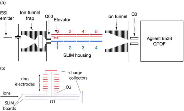
(a) Schematic diagram of the SLIM setup used to test the “elevator”. Ions can move on either the straight pass (blue) or through the elevator to a second SLIM level (red). (b) Schematic diagram of the “elevator” SLIM module utilizing two charge collectors for the straight pass (blue) or the “elevator” pass (red). rf parameters of 1.2 MHz and 200 Vp-p were applied to SLIM and to the ring electrodes. A dc gradient of 11 V/ cm was established through SLIM to drive the ions.
SLIM Elevator
In brief, the linear SLIM module consisted of two arrays of planar electrodes that are deposited (~40 μm thick) on flat printed circuit board material. The rf waveform was applied to the central rung electrodes (out-of-phase rf applied to adjacent electrodes) prevents ions from approaching the surfaces. Lateral confinement is achieved by applying dc potentials to the guard electrodes. In the current arrangement, one guard electrode is positioned to each side of four rung electrodes on each of the two mirror image surfaces. Ions are moved axially by superimposing a dc gradient on the rung electrodes. Ion manipulations can be achieved by varying the geometry of, or the electric fields applied to the rung and guard electrodes. To date, all SLIM have involved a single level; i.e., ions confined to a plane but where ion turns or switches have been demonstrated for two-dimensional ion manipulations within that plane.1–3,5,8–14,19,20 An initial design for moving ions to a different SLIM level is shown in Figure 2. An orifice (4.3 mm i.d.) was introduced to which a dc potential could be applied (i.e., without rf). The SLIM used two such parallel surfaces separated by a 4.75 mm gap, where one of the orifices on one surface was covered with copper foil while the other orifice on the other surface was kept open (see Figure 1b). Two elevator-SLIM components were connected through a series of eight ring electrodes of 4.3 mm i.d., 0.8 mm thick, and 0.6 mm apart to form the SLIM elevator. The same out-of-phase rf waveform, 1.2 MHz and 200 Vp-p, applied to adjacent rung electrodes was also applied to adjacent ring electrodes. The width of the rung electrodes was also varied. At the entrance and exit of the elevator surface, the width of the first 11 rung electrodes was kept at 5.3 mm to seamlessly integrate with other straight-SLIM modules. The width of rung electrodes was varied then from 5.3 mm to 9.9 mm over four rung electrodes. Ion simulations showed a split in the ion plume between the two surfaces at a rung width of 5.3 mm due to the dc field penetration from the guard electrodes4 (see Supporting Information, Figure S1), while the ions traveled as a single plume between the surfaces at a rung electrode width of ~9.9 mm. To enable a single plume to enter the elevator and be efficiently transported to the next level (i.e., without a split ion beam thus preventing two populations that are temporally and spatially separated upon exiting the elevator orifice), a gradual variation in the rung electrode width was introduced adjacent to the orifice. Plume splitting was avoided without affecting the lateral ion confinement by increasing the width of the rung electrodes.
Figure 2.
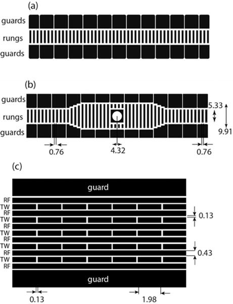
Schematic diagram of (a) a straight-SLIM surface and (b) an elevator-SLIM surface showing key dimensions (in millimeters). The width of the rung electrodes was varied between 5.33 and 9.91 mm. (c) Schematic diagram of a linear TW-SLIM surface segment.
TW-SLIM Escalator
Details of the operation and characterization of single-plane TW-SLIM modules have been given elsewhere.12 In the present work a SLIM incorporating two traveling wave escalator components (each comprised of two small PCB fabricated component segments) was assembled (Figure 3). A slight difference in dimensions between the top and bottom segments was needed to minimize the spacing between surfaces at their junctions caused by their ~26° angle. The SLIM level 2 formed by segments C and H was elevated from level 1 (A, F, E, and J segments) by ~22.6 mm. The two TW-SLIM levels each had a 4.75 mm gap achieved using aluminum spacers, and the escalator segments attached using custom-made 3D printed parts. In this work, the TW was created by switching the dc on and off to individual electrodes of each eight electrode set.12 The TW-SLIM uses 5 arrays of TW dc electrodes interleaved with, and separated from, rf electrodes by a distance of 0.13 mm. Each TW electrode has a length of 1.98 mm and width of 0.43 mm (Figure 2c). The dc guard electrodes were 5.08 mm wide and extend along the ion path. rf waveforms at 1 MHz, 180° out-of- phase for adjacent electrodes were applied to the six 31.2 cm long rf electrodes on each surface to create a confining effective potential inhibiting loss of ions to the two surfaces.
Figure 3.

Schematic diagram illustrating the components of the TW escalator. All PCB surfaces used were 66 mm wide. The top SLIM surfaces (A–E) have lengths of A = 84 mm, B = 50 mm, C = 49 mm, D = 50 mm, and E = 80 mm. The bottom surfaces (F–J) have lengths of F = 85 mm, G = 50 mm, H = 50 mm, I = 51 mm, and J = 82 mm.
RESULTS AND DISCUSSION
Here we describe the development and initial evaluation of two new SLIM modules that can be used to move ions between different SLIM levels. Efficient ion transmission across the SLIM levels using the elevator and escalator modules has been verified by both ion trajectory simulations and experimental measurements. Transmitting similar MS peak distributions using the elevator and straight pass setups indicates a relatively well-defined ion plume transmitted over a wide m/z range through the elevator. Moreover, achieving similar IM resolution utilizing the escalator and a straight module of the same length illustrates the potential of achieving unattainable resolution by compact SLIM designs. Therefore, the SLIM elevator can be used to move ions through a well-defined 90° turns to different levels, and the SLIM escalator can be used to guide ions at smaller angles between levels, with the choice presently depending on available space (i.e., device size) and ease of fabrication.
Elevator
In order to evaluate the ion transmission, two charge collectors were positioned at the end of the straight pass (blue) and at the end of the ring electrodes (red) for ion current measurements for the two ion paths (Figure 1b). The voltage difference, ΔV, between the two orifices (labeled O1 and O2 in Figure 1b), determines the ion path. If the two orifices have the same voltage (i.e., ΔV = 0) ions travel on a linear path to the straight pass charge collector. Varying the voltage difference between the two orifices is used to steer ions into or away from the elevator channel (the ring electrodes in Figure 1b). A dc gradient of 11 V/cm was established through the rung electrodes using a resistive chain to drive ions through SLIM. However, the dc voltages on orifices O1 and O2 were controlled independently of the SLIM dc gradient but were kept within a few volts of the neighboring rung electrodes for optimum ion transmission. In addition, the guard electrodes were kept 5 V higher than the rung electrodes to confine ions laterally. The dc gradient to the ring electrodes was also kept at ~11 V/cm. As shown in Figure 4a, at ΔV = 0, the ion transmission is maximum ~310 pA for the straight pass (see ion simulations in Figure 4b). As the voltage of O2 is increased, while fixing the voltage of O1, (ΔV > 0) the signal reaching the charge detector decreases as the ions are “pushed” toward the bottom SLIM surface. However, as O2 voltage decreases (ΔV < 0) ions are steered toward the O2 and enter into the ring electrodes, rationalizing the decrease in signal observed in the straight pass charge collector. Additionally, looking at the signal observed at the elevator charge collector indicates that the decrease corresponds to ions entering the elevator. Figure 4b shows simulation of ion trajectories with ΔV = −2 V, indicating about 66% ions are directed into the elevator. At ΔV ~ −4 V, the maximum ion transmission (320 pA) was observed at the elevator charge collector, similar to the signal observed at the straight pass charge collector (Figure 4b bottom panel shows the ion trajectories). As ΔV is decreased below −4 V, the ion current entering the elevator decreased. In the current experiment setup, the voltages on the first ring electrode after O2 and on the last ring electrode before the charge collector were kept constant while the voltage of O2 was varied. As ΔV was decreased below −4 V, a barrier was created that trapped ions and decreased the number of ions entering the elevator. Interesting to observe that within a narrow voltage range of 4 V, the ion beam can be efficiently and completely steered indicating that the elevator setup can be efficiently used as a switch.
Figure 4.
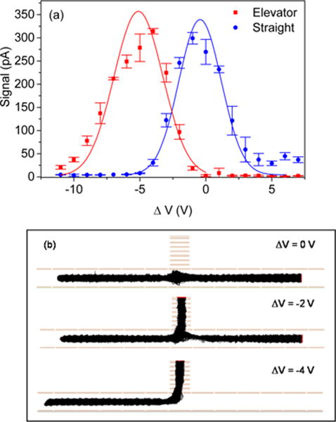
(a) Ion-current measurements for melittin ions in the straight (blue) and elevator (red) modes as a function of the voltage difference between the two orifices in elevator surface (see Figure 1). Ion currents of ~350 pA were measured at the device entrance. (b) Top panel shows trajectories at ΔV = 0 V (i.e., straight mode), middle panel at ΔV = −2 V showing 66% transmission through the elevator, and the bottom panel shows the ion trajectories at ΔV = −4 V and 100% transmission through the elevator. Simulations were performed with 250 particles using rf parameters of 150 Vp-p at 1 MHz.
The elevator setup was further evaluated for the range of m/z transmitted within the experimental parameters used and compared to straight pass setup. An Agilent tune mixture was used for this setup as it contains peaks across a broad m/z range. The first SLIM setup is the straight pass where four SLIM modules were assembled together in a straight fashion (blue, Figure 1) to form a 30.48 cm long device. In this setup, the first module is an elevator module where the two orifices (O1 and O2, Figure 3) had the same voltage. The second, third, and fourth SLIM modules were straight modules (similar to the one in Figure 2a). The second SLIM setup is the elevator setup where five SLIM modules and a set of ring electrodes was assembled (red, Figure 1). In the elevator setup, the first and second SLIM modules are elevator modules that are a mirror of each other and connected through eight ring electrodes. The third, fourth, and fifth SLIM modules were straight modules (similar to Figure 2a). In the first elevator module, the voltages of orifices O1 and O2 were optimized to steer ions into the elevators as illustrated in Figure 4. A dc gradient of 11 V/cm was established to drive ions through SLIM in the two setups. As shown in Figure 5, the mass spectra collected with the straight and elevator modes have similar m/z ranges (600–2700). Those similar peak distributions indicate a relatively sharp ion plume turn into the elevator over the m/z range observed.
Figure 5.
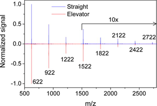
Mass spectra for an Agilent tune mixture collected in the straight (blue) and in the elevator (red) mode showing similar m/z distribution.
Moving ions between two levels can be also performed using traveling waves (TW) instead of a constant dc field as described above. Ion trajectory simulations using TW were performed using SIMION 8.1 on an elevator module and show (Figure 6) that efficient operation of an elevator-based SLIM module is feasible. The stacked-ring electrodes were replaced with a double-sided surface design that has one TW electrode at the edge of the orifice to transfer ions between two SLIM levels (Supporting Information, Figure S2). Ion trajectory simulations are shown in Figure 6 for the optimum transmission in a linear path and when the elevator is enabled. The ions trajectories are shown in a cross-sectional view, i.e., between the surfaces. The elevator is enabled by applying a bias voltage to the two TW electrodes (which act as repeller electrodes) opposite to the orifice in order to steer ions into the orifice. Supporting Information (Figure S3) shows a top view of Figure 6a, while Figure S4 illustrates the effect of the voltage applied to the repeller electrodes.
Figure 6.
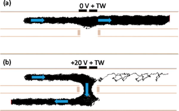
Cross-sectional view of SIMION ion trajectory simulations for a TW-SLIM elevator module operating when the elevator is (a) disabled and (b) enabled by applying a bias voltage to the two TW electrodes across from the orifice. Arrows indicate the direction of ion motion. Simulations were performed with 100 particles using rf parameters of 150 Vp-p at 1 MHz and TW parameters of 30 V amplitude at speed of 200 m/s and a sequence of 11110000.
Escalator
The TW escalator module was evaluated to ensure nearly lossless ion transmission between the SLIM levels using total ion current measurements at several positions along the ion path. Moreover, we investigated the obtained separations as a function of TW speed and compared it to a linear TW-SLIM section of similar length for ion mobility resolution. The TW-SLIM escalator ion transmission was evaluated using the ion current of the Agilent tune mixture measured as a function of position along the ion path using the optimized TW parameters. Eight sets of measurements were conducted by positioning the probe at 1, 4, 7, 10, 15, 21, 26, and 30 cm from the entrance of the TW-SLIM escalator module. The measured ion current indicates an initial loss of ion current (25%) between 1 and 4 cm and which can be attributed to the difference in confinement fields between the TW-SLIM module and the preceding quadrupole (Q00). Better matching of the electric field at the entrance of SLIM with another ion guide such as the rectangular ion funnel can mitigate losses at the entrance of SLIM.21 However, the ion transmission inside the TW-SLIM escalator module is essentially lossless illustrating the efficient transmission of ion beam among TW-SLIM levels using the TW escalator (Figure 7a).
Figure 7.
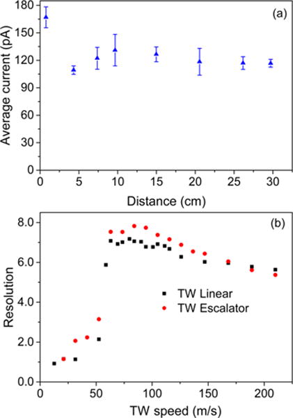
(a) Ion current measured as a function of the distance from the entrance of TW-SLIM escalator module. Error bars represent standard deviations from triplicate measurements. Measurements were made by inserting a conducting probe in between the two TW-SLIM surfaces at each point. The ~25% decrease at the entrance is attributed to m/z species not effectively transmitted by the SLIM (i.e., the mismatch between the ion injection and the SLIM ranges of optimal ion confinement and transmission). (b) Ion mobility resolution measured as a function of TW speed for a TW amplitude of 30 V, a TW sequence of 11110000, guard bias of 15 V, and rf amplitude (Vp-p) of 320 V for the linear TW-SLIM and TW-SLIM escalator arrangements.
In addition to the good ion transmission, it is crucial to ensure the preservation of IM resolution (a useful performance metric for TW-IM12,22,23) when transporting ions between levels. Thus, the resolution of m/z 622 and 922 ions (R622–922) is used here and calculated using the expression: , where t922 and t622 represent the arrival times of m/z 922 and 622 ions while Δt922 and Δt622 are the fwhm of the m/z 922 and 622 peaks, respectively. The distribution of the applied voltages in a repeating pattern to each set of eight electrodes is determined by TW sequence. Symmetric TW sequence (11110000) was adopted in the current study where 0 means applying 0 V, while 1 means applying the traveling wave amplitude (e.g., 30 V) to the specified electrode.12 The applied voltages were stepped one electrode at a time in the direction of ion motion.11,12 The TW amplitude was also optimized to achieve higher ion mobility resolution, thus 30 V was used throughout the study. Figure 7b shows the effects of varying the TW speed on the measured IM resolution of an escalator and a linear TW-SLIM modules. The observed trend of the TW speed on the measured resolution achieved by the escalator TW-SLIM module are similar to those achieved by the linear TW-SLIM module.12 As illustrated in Figure 7b, the linear (30.5 cm) and the escalator (31.2 cm) TW-SLIM modules provided similar IM separations. The optimum resolution of 7.8 was achieved at a TW speed of 84 m/s for the escalator TW-SLIM which is comparable to the resolution of 7.1 achieved by the linear TW-SLIM module at the same conditions. Therefore, ions can be transported through the TW escalator 3D assembly without any loss in the sensitivity or IM resolution.
CONCLUSION
We describe SLIM elevator and TW-SLIM escalator concepts for moving ions between levels of multilevel SLIM devices and that we have implemented and initially evaluated for their ion transmission and ion mobility resolution. The “elevator” used an orifice in one of the SLIM surfaces in conjunction with a stack of circular “ring” electrodes to move ions between SLIM modules. Through ion simulation and optimization of the field inside the elevator, ions can be transmitted in a straight path or steered into the elevator ring electrodes. Experimental results indicated that similar signal level was observed in the elevator and in the straight mode. The mass spectra for peaks of m/z 600–2700 were found to be similar in either the straight or the elevator mode.
We also evaluated the performance of the TW-SLIM escalator module where ions are transported efficiently between two SLIM levels. Ion current measurements illustrated the lossless transmission of ions between the SLIM levels through the TW-SLIM escalators. Moreover, the ion mobility resolution obtained using the TW-SLIM escalator module was comparable to that obtained by a linear module indicating the lack of any loss in resolution as the ions move among SLIM levels. The initial performance of the elevator and escalator pave the way to construct more advanced SLIM structures to enable multilayer SLIM devices. Multilayer SLIM can be utilized for many applications, such as performing different ion chemistry on different levels or to provide greatly extended ion path lengths to increase the resolution achievable with ion mobility separations. Moreover, both of the elevator and TW escalator can be also used as switches, e.g., for steering selected ion peaks into different paths.
Supplementary Material
Acknowledgments
Portions of this research were supported by the Laboratory Directed Research and Development (LDRD) program at the Pacific Northwest National Laboratory, National Institutes of Health (NIH) NIGMS Proteomics Research Resource under Grant P41 GM103493 and by the Department of Energy Office of Biological and Environmental Research Genome Sciences Program under the Pan-Omics Project. Work was performed in the Environmental Molecular Sciences Laboratory (EMSL), a DOE national scientific user facility at the Pacific Northwest National Laboratory (PNNL) in Richland WA. PNNL is operated by Battelle for the DOE under Contract DE-AC05-76RL0 1830.
Footnotes
Supporting Information
The Supporting Information is available free of charge on the ACS Publications website at DOI: 10.1021/acs.analchem.6b04500.
Top and side views for SIMION ion trajectory simulations; enlarged 3D CAD image of a TW-elevator board; and cross sectional views of SIMION ion trajectory simulation of a TW-SLIM elevator module (PDF)
ORCID
Yehia M. Ibrahim: 0000-0001-6085-193X
Richard D. Smith: 0000-0002-2381-2349
Notes
The authors declare no competing financial interest.
References
- 1.Chen TC, Ibrahim YM, Webb IK, Garimella SV, Zhang X, Hamid AM, Deng L, Karnesky WE, Prost SA, Sandoval JA, Norheim RV, Anderson GA, Tolmachev AV, Baker ES, Smith RD. Anal Chem. 2016;88:1728–1733. doi: 10.1021/acs.analchem.5b03910. [DOI] [PMC free article] [PubMed] [Google Scholar]
- 2.Webb IK, Garimella SV, Tolmachev AV, Chen TC, Zhang X, Cox JT, Norheim RV, Prost SA, LaMarche B, Anderson GA, Ibrahim YM, Smith RD. Anal Chem. 2014;86:9632–9637. doi: 10.1021/ac502139e. [DOI] [PMC free article] [PubMed] [Google Scholar]
- 3.Webb IK, Garimella SV, Tolmachev AV, Chen TC, Zhang X, Norheim RV, Prost SA, LaMarche B, Anderson GA, Ibrahim YM, Smith RD. Anal Chem. 2014;86:9169–9176. doi: 10.1021/ac502055e. [DOI] [PMC free article] [PubMed] [Google Scholar]
- 4.Garimella SVB, Ibrahim YM, Webb IK, Tolmachev AV, Zhang XY, Prost SA, Anderson GA, Smith RD. J Am Soc Mass Spectrom. 2014;25:1890–1896. doi: 10.1007/s13361-014-0976-y. [DOI] [PMC free article] [PubMed] [Google Scholar]
- 5.Tolmachev AV, Webb IK, Ibrahim YM, Garimella SVB, Zhang XY, Anderson GA, Smith RD. Anal Chem. 2014;86:9162–9168. doi: 10.1021/ac502054p. [DOI] [PMC free article] [PubMed] [Google Scholar]
- 6.Gerlich D. Adv Chem Phys. 1992;82:1–176. [Google Scholar]
- 7.Garimella SV, Ibrahim YM, Webb IK, Tolmachev AV, Zhang X, Prost SA, Anderson GA, Smith RD. J Am Soc Mass Spectrom. 2014;25:1890–1896. doi: 10.1007/s13361-014-0976-y. [DOI] [PMC free article] [PubMed] [Google Scholar]
- 8.Zhang XY, Garimella SVB, Prost SA, Webb IK, Chen TC, Tang KQ, Tolmachev AV, Norheim RV, Baker ES, Anderson GA, Ibrahim YM, Smith RD. Anal Chem. 2015;87:6010–6016. doi: 10.1021/acs.analchem.5b00214. [DOI] [PMC free article] [PubMed] [Google Scholar]
- 9.Webb IK, Garimella SV, Norheim RV, Baker ES, Ibrahim YM, Smith RD. J Am Soc Mass Spectrom. 2016;27:1285–1288. doi: 10.1007/s13361-016-1397-x. [DOI] [PMC free article] [PubMed] [Google Scholar]
- 10.Deng L, Ibrahim YM, Hamid AM, Garimella SVB, Webb IK, Zheng X, Prost SA, Sandoval JA, Norheim RV, Anderson GA, Tolmachev AV, Baker ES, Smith RD. Anal Chem. 2016;88:8957–8964. doi: 10.1021/acs.analchem.6b01915. [DOI] [PMC free article] [PubMed] [Google Scholar]
- 11.Hamid AM, Garimella SVB, Ibrahim YM, Deng L, Zheng X, Webb IK, Anderson GA, Prost SA, Norheim RV, Tolmachev AV, Baker ES, Smith RD. Anal Chem. 2016;88:8949–8956. doi: 10.1021/acs.analchem.6b01914. [DOI] [PMC free article] [PubMed] [Google Scholar]
- 12.Hamid AM, Ibrahim YM, Garimella SV, Webb IK, Deng L, Chen T-C, Anderson GA, Prost SA, Norheim RV, Tolmachev AV, Smith RD. Anal Chem. 2015;87:11301–11308. doi: 10.1021/acs.analchem.5b02481. [DOI] [PMC free article] [PubMed] [Google Scholar]
- 13.Deng L, Ibrahim YM, Baker ES, Aly NA, Hamid AM, Zhang X, Zheng X, Garimella SVB, Webb IK, Prost SA, Sandoval JA, Norheim RV, Anderson GA, Tolmachev AV, Smith RD. Chemistry Select. 2016;1:2396–2399. doi: 10.1002/slct.201600460. [DOI] [PMC free article] [PubMed] [Google Scholar]
- 14.Deng L, Ibrahim YM, Garimella SVB, Webb IK, Hamid AM, Norheim RV, Prost SA, Sandoval JA, Baker ES, Smith RD. Anal Chem. 2016;88:10143–10150. doi: 10.1021/acs.analchem.6b02678. [DOI] [PMC free article] [PubMed] [Google Scholar]
- 15.Garimella SVB, Hamid AM, Deng L, Ibrahim YM, Webb IK, Baker ES, Prost SA, Norheim RV, Anderson GA, Smith RD. Anal Chem. 2016;88:11877. doi: 10.1021/acs.analchem.6b03660. [DOI] [PMC free article] [PubMed] [Google Scholar]
- 16.Clowers BH, Ibrahim YM, Prior DC, Danielson WF, 3rd, Belov ME, Smith RD. Anal Chem. 2008;80:612–623. doi: 10.1021/ac701648p. [DOI] [PMC free article] [PubMed] [Google Scholar]
- 17.Ibrahim YM, Belov ME, Liyu AV, Smith RD. Anal Chem. 2008;80:5367–5376. doi: 10.1021/ac8003488. [DOI] [PMC free article] [PubMed] [Google Scholar]
- 18.Ibrahim YM, Baker ES, Danielson WF, III, Norheim RV, Prior DC, Anderson GA, Belov ME, Smith RD. Int J Mass Spectrom. 2015;377:655–662. doi: 10.1016/j.ijms.2014.07.034. [DOI] [PMC free article] [PubMed] [Google Scholar]
- 19.Allen SJ, Eaton RM, Bush MF. Anal Chem. 2016;88:9118–9126. doi: 10.1021/acs.analchem.6b02089. [DOI] [PubMed] [Google Scholar]
- 20.Garimella SVB, Ibrahim YM, Webb IK, Ipsen AB, Chen TC, Tolmachev AV, Baker ES, Anderson GA, Smith RD. Analyst. 2015;140:6845–6852. doi: 10.1039/c5an00844a. [DOI] [PMC free article] [PubMed] [Google Scholar]
- 21.Chen T-C, Webb IK, Prost SA, Harrer MB, Norheim RV, Tang K, Ibrahim YM, Smith RD. Anal Chem. 2015;87:716–722. doi: 10.1021/ac503564c. [DOI] [PMC free article] [PubMed] [Google Scholar]
- 22.Siems WF, Wu C, Tarver EE, Hill HH, Jr, Larsen PR, McMinn DG. Anal Chem. 1994;66:4195–4201. [Google Scholar]
- 23.May JC, McLean JA. Int J Ion Mobility Spectrom. 2013;16:85–94. doi: 10.1007/s12127-013-0123-7. [DOI] [PMC free article] [PubMed] [Google Scholar]
Associated Data
This section collects any data citations, data availability statements, or supplementary materials included in this article.


