SUMMARY
Aim of the study
It is well known by previous important studies that mandible flexes during different jaw movements. According to this assumption it is very important to know how implant supported fixed partial dentures could restrict mandibular movements and, could lead to excess strain accumulation that could modify the resolution of implant treatment.
The aim of our project is to create a bio-faithful model able to recreate mandibular movements, during three point bending test methods of (FIXED –PARTIAL –DENTURES) FPDs, to avoid a not flexible metal base, where models’ properties doesn’t allow to obtain a bio-faithful simulation during testing phases.
Materials and methods
2 implants (premium Sweden and Martina®) were embedded in mandible resin section to mimic osteointegrated implants in premolar and molar areas, in order to recreate a Kennedy Class II configuration. Our mandible test simulator was creating according to the measurement obtained according to the study of Schwartz-Dabney and Dechow (2002). Sample so created is tested with testing machine (Instron 5566®, UK) adopting the three point bending mechanical tests configuration.
Discussion and conclusion
We can admit that oral cavity is a bio-dynamic system, where different variables incurr, so it’s very important that experimental conditions simulate clinical environment. Experimentation should be based on the correlation between the failure mechanisms exhibited for in vitro samples and those observed in fractured clinical prostheses made of the same composition and processing conditions. A bio-faithful model could reduce this wide range between in vitro and in vivo study experimentation.
Keywords: bio-faithful, model, implant testing, three point bending, test
Introduction
The human mandible has been shown to deform as a direct consequence of jaw movement (1, 2). In a recent article have been proposed four patterns of mandibular deformation: symphyseal bending associated with medial convergence or corporal approximation; dorsoventral shear; corporal rotation; and anteroposterior shear (3). Mandibular flexure is a multifactorial phenomenon with bone quality and quantity, implant location and number, impression technique, and prosthesis design proposed as contributing factors. Nowadays the importance of mandibular flexure on the success of implant treatment is currently unclear, but results of studies suggest that mandibular flexure should be considered during FPDs’ design (4–6). A logical method to minimize the effect of mandibular flexure could be the use of a sectional prosthesis design such as multiple implant-supported restorations or a prosthesis divided along the symphysis region (6). Analysis of stress and strain is an important value in a bio-dynamic system, in fact limited strain in the mandible may stimulate bone formation while excessive strain might activate bone resorption (7).
The relationship between strain and bone formation has been an area of interest in orthopedic surgery since the 1980s. Carter (8) proposed a non linear relationship between bone mass and strain. He suggested that, in mature bone, a window of strain exists where the osteoblastic activity is balanced by osteoclastic activity under functional loading. In fact material properties and their variations in individual bone organs are important for understanding bone adaptation and quality at a tissue level, and are essential for accurate mechanical models. A lot of study demonstrate: 1) the regional variability in mandibular material properties, 2) the effect of this variability on the modelling of mandibular function and 3) the relationship of this variability to mandibular structure and function.
Materials and methods
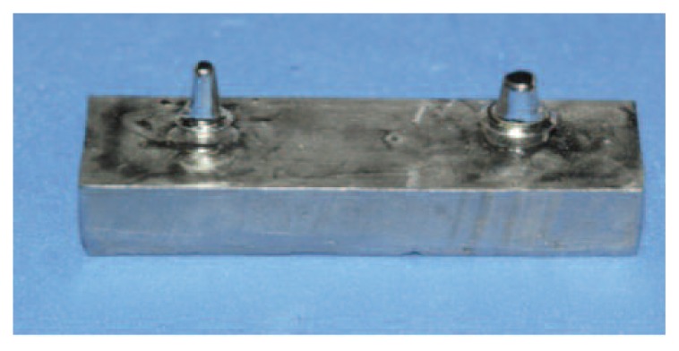
We have just studied zirconium ceramic FPDs, (9) in order to evaluate stress, strain and especially adhesion, but during these tests we always use a steell model, that was define fixed or not bio-faithful (Figure 1). For this reason, we decided to test these FPDs, with a bio-faithful system. According to the study of Schwartz-Dabney and Dechow (10) and Apicella et al. (11), we created a model of resin mandible able to recreate a non dentate section.
Figure 1.
First steel model used during our test. Young’s modulus 200 Gpa.
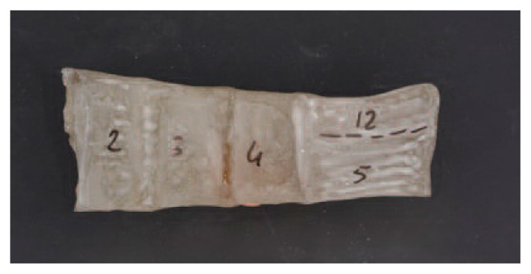
A core of unsaturated polyester (Kimipol Chemical Industries, Teramo, Italy) simulates the spongy bone then we divided the mandibular simulator in 5 sections for each side corresponding to the craniometric measurements of human edentulus mandibles (Figure 2).
Figure 2.
Section of mandible divided in section according to Schwartz-Dabney and Dechow.
In the mandibular simulator, the cortical bone was simulated by a layer of glass-fiber-reinforced resin (GFRR); the thickness of the GFRR layer was created according to the average thickness of the cortical bone (3mm) of a human dentate mandible in the premolar area (Schwartz-Dabney & Dechow 2002).
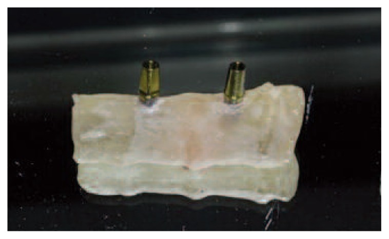
The core was obtained with a silicone mold, whereas the titanium fixtures were positioned like real implants. After the creation of mandible model we located two implants (Sweden and MartinaR premium), for each specimens with inter-implantar distance of 2,2 cm, in order to create the correct space to recreate a FPDs with three elements: a first premolar, a second premolar and a first molar. We located implants with the same procedures of a normal surgical phase (Figure 3).
Figure 3.
Saple with two implant embedded.
Upon each implant we screw standard abutment Sweden and Martina®, with a torque of 25 Ncm. The mechanical properties of the model are in according to the Halpin-Tsai model (Halpin and Kardos 1976) (12, 13).
| (11) |
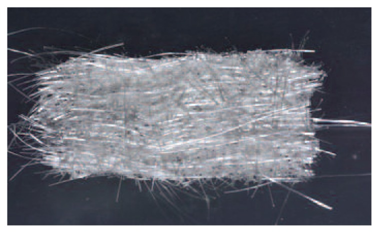
E3 is the elastic modulus in the maximum stiffness direction, E2 is the elastic modulus in the direction normal to the maximum stiffness direction, G23 is the shear elastic modulus in the 23 plane and v23 is Poisson’s ratio in the 23 plane. f is the glass-fibers volume fraction, Ef is the elastic modulus of glass-fibers, Em is the elastic modulus of the resin matrix, Gf is the shear elastic modulus of glass fibers Gm is the shear elastic modulus of resin matrix, vf is Poisson’s ratio of glas-fibers (Figure 4) and vm is Poisson’s ratio of the resin matrix (11) (Table 1).
Figure 4.
Resin matrix adopted to create cortical bone.
Table 1.
Values obtained to the study of Schwartz-Dabney and Dechow (10) and adopted to create our sample.
| Thickness (mm) | Maximum Stiffness Directin | E 2( GPa) | E3 (GPa) | G23 (Gpa) | V 23 | |
|---|---|---|---|---|---|---|
| Buccal side | ||||||
| Sym | 3.1 | 4.5 (13.5)std | 15.8 | 26.2 | 6.8 | 0.23 |
|
| ||||||
| Infbor | 2.7–2.1 | 13.2–24.7(18.1–12.1)std | 17.5 | 29.5–22.9 | 7.1 | 0.18–0.27 |
|
| ||||||
| Midbod | 2.3 | 37.5 (10.6) std | 18.8 | 26.9 | 7.2 | 0.22 |
|
| ||||||
| Lingual side | ||||||
| Sym | 3.1 | −8.9 (31.7) std | 17.8 | 25.6 | 7.3 | 0.26 |
|
| ||||||
| Infbor | 2.5–1.9 | −4.4 – 17.9 (9–16.9) std | 17.8–18.4 | 28.1–28.9 | 7.9–7.6 | 0.20–0.18 |
|
| ||||||
| Midbod | 1.7 | 15.2 (18.4) std | 18.6 | 24.4 | 6.8 | 0.21 |
CAD_CAM project
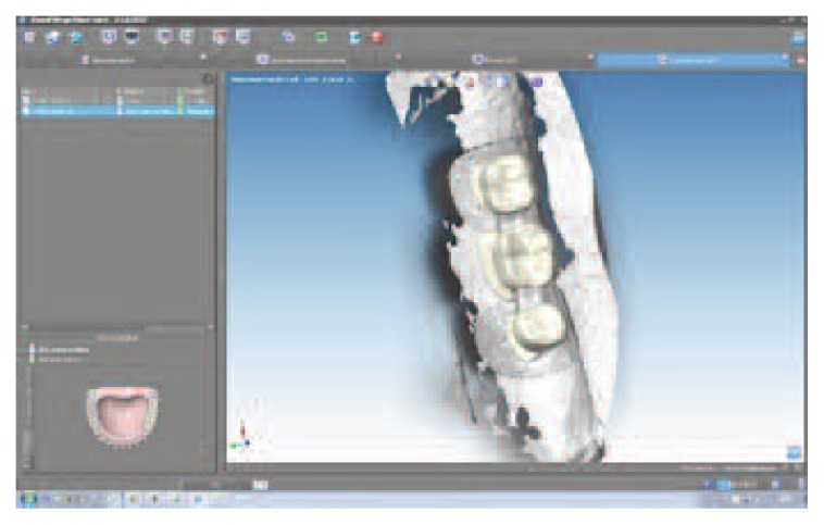
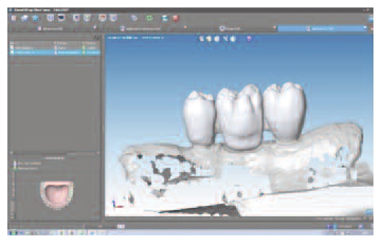
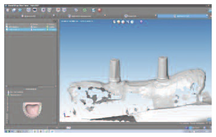
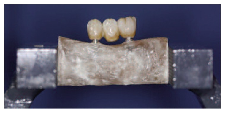
Using Dental Wings Software we scan our model, to create a virtual model and design prosthesis and framework with specifical parametres and then with the virtual articulator we improve the kinematic analysis. The precise occlusion simulation significantly reduces the time required for chairside occlusion adjustment, facilitating the overall procedures (Figures 5, 6, 7). During testing phases extremities of mandible section have to be fitted in a vise, so that every deformations could happen during test, but at the same time the bending machine didn’t push it during action. Every distance has been calculated and different stability tests have done (distance a-0.6 cm/ distance b-2 cm). These distances have been calculated, with different adjustments conduced by previous tests, allowing the removal of FPDs with a fluid operation.
Figure 5.
CAD project framework.
Figure 6.
CAD project FPD.
Figure 7.
CAD project sample.
We marked each specimens to the right and left sides in the point c, to be sure that we don’t have movement during tests (Figure 8).
Figure 8.
Sample fitted in a vise ( a= 0.6 mm/ b= 2 cm).
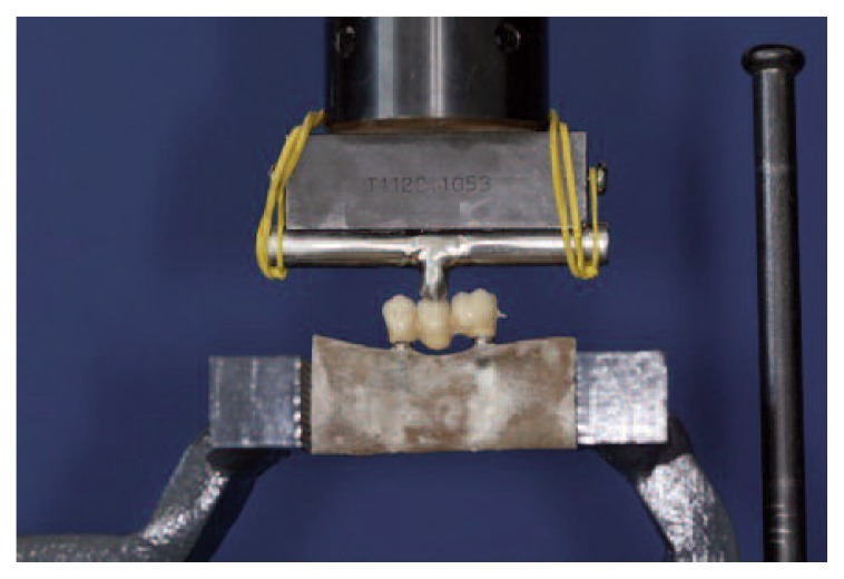
Sample thus made could be subjected to a three point bending test. We used an Instron 5566 machine. Fixed partial dentures were analyzed according to three-point-bending method. Load was applied at the exact center of the structures: in other words, in the central connector (second mandible premolar), and the lower constraints made up by the implant structures.
In order to recreate a first class occlusion we provide a fusion of a second maxillar premolar and then it was welded in the middle of roller bar. Before tests, ideally, each samples’ occlusion has been calibrated (Figure 9).
Figure 9.
Sample during three point bending test.
Discussions
Analyzing literature we can admit that: randomized, controlled clinical studies are regarded as the optimal approach to evaluate the performance of biomaterials and design aspects of dental fixed prosthesis. However, these studies are extremely expensive and the variables that control overall performance under the vast variety of conditions that are encountered in clinical practices must be limited. Biomechanic tests and analyses are very important because could can reduce the number of clinical studies that must be conduced to characterize the performance of a prosthetic system.
Essentially in an experimental mechanical system there will be a great relationships between biomechanical properties and mechanical failures including crack formation, chipping, bond failure and bulk fracture. On the other side with this type of model we can analyze different FPDs enhancing material and their properties avoiding not real data as a direct consequence of model stiffness.
A very wide application of mechanical tests could be conduce with this model: three/four point bending, shear bond test, photo-elastic analysis, dynamometric failure tests, but tests used attempts should be made to simulate as closely as possible the range of conditions associated with the oral cavity. If the conditions of the dental structure of interest can be simulated, the rest is classified as being “structurally representative”. Nowadays in a in vitro test we can simulate, for example, crown and bridge FPDs on implant geometry, a periodontal ligament type material adopted to the root area of the tooth or simulated tooth but it is virtually impossible to model all conditions in a single experiment. Ideally one should design an experiment for the worst case and best case scenarios (14). If we analyze literature (15–17) we can find a lot of studies where implants are embedded in resin; sections or mandible, with a young modulus of 2.5–3 Gpa, values that could be related to trabecular bone, but if we consider bone like a complex system we must not forget cortical bone and its orthotropic properties. According to the non linear relationship of bone (8) and its anisotropic structure, means that its mechanical properties, we must consider two orthogonal directions:
- longitudinal, parallel to osteon and loading direction
- transverse, creating a right angle to the long axis of bone.
Nowadays composites are materials used to create bone, but during this process we have to admit that bone is made of collagen fibres and an inorganic matrix, so when we create a model with fiber, the young’s modulus of aligned fibre composites can be calculated using the Rule of mixtures and the inverse Rule of mixtures for loading parallel and perpendicular to the fibres respectively.
In our study we have adopted Halpin-Tsai model, because just used in a previous study, but Rule of mixtures and the Inverse rules of mixtures is a valid scientific option.
It’s very important to know that also with a sample with two layers of polymers materials, we are not able to recreate cortical bone properties because the composite model of the bone miscrostructure is highly simplified. For better approximation we should have a model with two layers: one provided to create hydroxyapatite-reinforced collagen in a single osteon and the second layer creating an hexagonal paching of osteons in a matrix of interstitial bone.
From a biomechanical point of view cortical bone has two different young’s modulus: (cortical bone, logitudinal fibre – young’s modulus 11–21 Gpa and Cortical bone, transverse fibre – young’s modulus 5–13 Gpa), and only the use of fiber could recreate this condition (18).
Fibers width selection, and young’s modulus properties in transverse and longitudinal sections, in our study has been related to the article of Berthelot (19).
Conclusion
It is advisable to adopt a bio-faithful model for implant testing, to avoid that young’s modulus and mechanical properties of model could modify our mechanical test results. We can maintain, according to literature data, that a bio-faithful model can offer a lot of conditions to reduce error related to testing methods adopted.
References
- 1.Al-Sukhun J, Helenius M, Lindqvist C, Kelleway J. Biomechanics of the mandible part 1: measurement of mandibular functional deformation using custom-fabricated displacement transducers. J Oral Maxillofacial Surg. 2006;64:1015–22. doi: 10.1016/j.joms.2006.03.009. [DOI] [PubMed] [Google Scholar]
- 2.Abdel-Latif H, Hobkirk J, Kelleway J. Functional mandibular deformation in edentulous subjects treated with dental implants. Int J Prosthodont. 2000;13:513–9. [PubMed] [Google Scholar]
- 3.Hylander W. Stress and strain in the mandibular symphysis of primates: a test of competing hypotheses. Am J Phys Anthropol. 1984;64:1–46. doi: 10.1002/ajpa.1330640102. [DOI] [PubMed] [Google Scholar]
- 4.Zarone F, Apicella A, Nicolais L, Aversa R, Sorrentino R. Mandibular flexure and stress build-up in mandibular full-arch fixed prostheses supported by osseointegrated implants. Clin Oral Implants Res. 2003;14:103–14. doi: 10.1034/j.1600-0501.2003.140114.x. [DOI] [PubMed] [Google Scholar]
- 5.El-Sheikh A, Abdel-Latif H, Howell P, Honkirk J. Midline mandibular deformation during nonmasticatory functional movements in edentulous subjects with dental implants. Int J Oral Maxillofac Implants. 2007;22:243–8. [PubMed] [Google Scholar]
- 6.Nokar S, Naini R. The effect of superstructure design on stress distribution in peri-implant bone during mandibular flexure. Int Oral Maxillofac Implants. 2010;25:31–7. [PubMed] [Google Scholar]
- 7.Frost H. Bone “mass” and the “mechanostat”: a proposal. Anat Rec. 1987;219:1–9. doi: 10.1002/ar.1092190104. [DOI] [PubMed] [Google Scholar]
- 8.Carter DR. Anisotropic analysis of strain rosette information from cortical bone. J Biomech. 1978;11:199–202. doi: 10.1016/0021-9290(78)90013-1. [DOI] [PubMed] [Google Scholar]
- 9.Cardelli P, Vertucci V, Balestra F, Montani M, Arcuri C. Mechanical evaluation and fem analysis of tress in fixed partial dentures zirconium ceramic. Oral implantol (Rome) 2013 Mar;:6. [PMC free article] [PubMed] [Google Scholar]
- 10.Schwartz-Dabney CL, Dechow PC. Edentulation alter material properties of cortical bone in the human mandible. J Dent Res. 2002;81(9):613–617. doi: 10.1177/154405910208100907. [DOI] [PubMed] [Google Scholar]
- 11.Apicella D, Veltri M, Balleri P, Apicella A, Ferrari M. Influence of abutment material on the fracture strength and failure modes of abutment-fixture assemblies when loaded in a bio-faithful simulation. Clin Oral Impl Res. 2010 doi: 10.1111/j.1600-0501.2010.01979.x. [DOI] [PubMed] [Google Scholar]
- 12.The Halpin-Tsai Equations: a review. Polymer engineering and science. 1976 May;16(5) [Google Scholar]
- 13.Usui T, Maki K, Toki Y, Shibasaki Y, Takanobu H, Takanishi A, Miller AJ. Mechanical strain on the human skull in a humanoid robotic model. American Journal of Orthodontics and Dentofacial Orthopedics. 2004;126:421–431. doi: 10.1016/j.ajodo.2003.02.009. [DOI] [PubMed] [Google Scholar]
- 14.Anusavice KJ, Kakar K, Ferree N. Which mechanical and physical testing methods are relevant for predicting the clinical performance of ceramic-based dental prostheses. Clin Oral Implants Res. 2007 Jun;18(Suppl 3):218–31. doi: 10.1111/j.1600-0501.2007.01460.x. [DOI] [PubMed] [Google Scholar]
- 15.Rosentritt M, Rembs A, Behr M, Hahnel S, Preis V. In vitro performance fo implant-supported monolithic zirconia crowns: influence of patient-specific toothcoloured abutments with titanium adhesive bases. Journal of dentistry. 2015 doi: 10.1016/j.jdent.2015.04.011. [DOI] [PubMed] [Google Scholar]
- 16.Ichim I, Kieser JA, Swain MV. Functional significance of strain distribution in human mandible under masticatory load: Numerical predictions. Swain archives of oral biology. 2007;52:465–473. doi: 10.1016/j.archoralbio.2006.10.020. [DOI] [PubMed] [Google Scholar]
- 17.Peri-implant Biomechanical responses to standard, short wide, and mini wide implants supporting single crown under axial and off-axial loading (an in vitro study) Journal of oral implantology. 2014;XL(1) doi: 10.1563/AAID-JOI-D-11-00102. [DOI] [PubMed] [Google Scholar]
- 18.Mechanical properties of bone. University of Cambridge; 2004–2015. TLP Library structure of bone and implant materials. [Google Scholar]
- 19.Berthelot JM, El Mahi A, Leblond P. Transverse cracking of cross-ply laminates: Part 2. Progressive widthwise cracking. Composites Part A 27°. 1996:1003–1010. [Google Scholar]


