

Abstract
Successful interpretation of available geophysical data requires experimental and theoretical information on the elasticity of solids under physical conditions of Earth's interior. Because iron is considered as major component in Earth's core, elastic properties of iron at high pressures and temperatures are very important for modeling its composition and dynamics. We use in situ x-ray diffraction data on ɛ-iron at static pressures up to 300 GPa and temperatures to 1,200 K to determine the Debye–Waller temperature factors and calculate aggregate sound velocities and Grüneisen parameter of ɛ-iron by using an approach that is based on Rietveld refinement at high pressures and temperatures.
The data on static compression of iron at ambient and elevated temperatures (1–4) provides important information on compressibility at the conditions present in Earth's deep interior. However, information on shear modulus, which is crucial for calculating sound velocities, is very limited. Mao et al. (5) published results of a study of elasticity of iron to a pressure of 220 GPa based on a novel method of determination of elastic moduli with diamond anvil cells (DAC) (6). This method utilizes the fact that in opposite anvil devices (like DAC) compression is not hydrostatic. As a result, positions of the reflections on the powder diffraction patterns depend not only on bulk modulus of the compressed material, but also on all of the elastic moduli and a value of deviatoric stress. The method cannot be used at high temperatures because deviatoric stress in DAC practically vanishes above ≈800 K (4). The mean sound velocities of hcp iron were extracted from phonon density measurements at pressures up to 153 GPa and ambient temperature (7, 8). Raman spectroscopy (9) of ɛ-Fe at pressures up to 150 GPa gave additional input to elastic properties of iron at high pressures. However, so far there are no experimental information on sound velocities of iron at pressure range of 300 GPa and high temperatures—conditions that are relevant to Earth's inner core.
The vibrations of individual atoms, as applied to intensities of x-ray diffraction peaks, control the Debye–Waller temperature factor B. This includes all wavelengths of phonons. As a result, the information on temperature factors has been used over years to determine Debye temperatures and Gruneisen parameters of different materials (10–15). The Debye temperature depends on aggregate elastic properties of a crystal—the adiabatic bulk modulus KS and shear modulus G (16). Moreover, it was demonstrated by Anderson (16) that the Debye temperature is primarily dependent on the shear modulus, and this opens the way, as we are going to show in the present study, to extract aggregate shear and compressional sound velocities from data on temperature factors.
Following Grimvall's (12) consideration and using dispersion relation (10, 11)
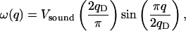 |
1 |
where ω is the circular frequency, Vsound is the sound velocities, q is the wave number of a lattice mode, and qD is the Debye cut-off wave number. We found for the Debye–Waller temperature factor (15) that
 |
2 |
where ℏ is the normalized Planck constant, kB the Boltzman constant, T the temperature, N the Avogadro's number, V the molar volume, ρ the density, Ks the adiabatic bulk modulus, and M the molar mass.
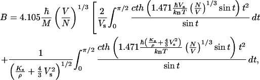
At high temperatures Eq. 2 could be significantly simplified:
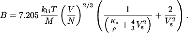 |
3 |
Eq. 3 makes clear that there is a correlation between shear sound velocities and the Debye–Waller temperature factor.
In Fig. 1, we compare the aggregate Vs for 30 metals with bcc, fcc, and hcp structures obtained from direct observations and calculated with Eq. 2 from temperature factors (10–12, 16–27). The standard deviation of calculated Vs from the experimentally observed shear sound velocities is less than 5%. For hcp metals (Fig. 1), the unit cell parameters (c/a) ratio covers the range from 1.55 to 1.65, which is the whole range expected for ɛ (hcp) iron (1, 4). For metals Zn and Cd (c/a = 1.88), Vs calculated with Eq. 2 differ from experimental ones by 30%. For α-Fe, aggregate shear moduli at pressures to 5 GPa were found (15), in good agreement with ultrasonic measurements. Therefore, if pressure and temperature dependence of the temperature factor, adiabatic bulk modulus, and molar volume are known, it is possible to estimate the aggregate sound velocity (both shear and compressional), as a function of P and T. Recently (4), we determined the equation of state for ɛ-Fe based on experimentally measured P–V–T data (pressures to 300 GPa and temperatures to 1,400 K). By combining those data with the data on the temperature factor of ɛ-Fe, as presented here, we can calculate the aggregate sound velocities of hcp iron at pressures corresponding to the physical conditions of Earth's core.
Figure 1.

Comparison of aggregate Vs obtained from direct observations and calculated with Eq. 2, using temperature factors for 30 metals with bcc (diamonds), fcc (squares), and hcp (hexagons) structures (10–12, 16–27). The standard deviation of calculated Vs from those experimentally observed is less than 5%. For hcp metals shown in the figure the c/a ratio covers the range from 1.55–1.65, or all reasonable values expected for ɛ (hcp) iron (1, 4).
Experimental Procedures
In situ x-ray experiments were performed on the beamline ID 30 at the European Synchrotron Radiation Facility (ESRF, Grenoble, France) and in Uppsala by using electrical (external and internal) heating. We also cross-checked volume determinations at high pressures and temperatures at Brookhaven National Laboratory (BNL, the beamline X-17C).
In Uppsala we obtained powder x-ray diffraction data with a Siemens x-ray system consisting of a direct-drive rotating anode generator (18 kW), a charge-coupled device (CCD) area detector (512 × 512 pixels), a zoom video system for sample visualization and alignment, and a capillary focusing system. MoKα radiation is focused on a sample position of 30–40 μm full width half maximum (FWHM). Sample to detector distance varied from 170–310 mm.
At the ID30 beamline at ESRF two focusing mirrors provide a bright monochromatic (λ from 0.3738–0.4245 A) x-ray beam in a 8 × 10 μm2 spot at the sample location from two phased undulators and a channel-cut Si (111) monochromator. Spectra are collected with an image-plate system (FastScan or MAR345) placed 250–350 mm from the sample.
At BNL we used polychromatic x-ray radiation collimated to 10 × 12 μm2 in FWHM. Powder diffraction data were collected with a Ge detector placed at the 2θ angle 8°.
In all experiments pressure was determined from the ɛ-Fe thermal equation of state (4) and, when possible, at pressures below 45 GPa, cross-checked from the equation of state of a pressure medium (Ar, NaCl, CsCl, etc.) (49, 50).
We heated the samples externally in a Mao–Bell-type DAC. Details of experimental set-up and a procedure are described elsewhere (4, 28). Examination of the samples following complete decompression after experiments did not reveal any signs of oxidation and/or contaminations.
Results and Discussion
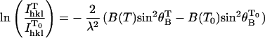
The integrated intensities of a Bragg reflection is related to the Debye–Waller factor: IBragg ≈ exp(−2B⋅sin2θB/λ) (10). An experimental determination of ln(Icor) versus (sin2θB/λ) (θB is the Bragg diffraction angle, λ the wavelength of radiation) should yield a straight line whose slope is −2B (“Wilson plot”) (10). We define Icor as an experimental intensity corrected for a number of factors [polarization, absorption, extinction, thermal diffusive scattering (TDS), preferred orientation, etc.]. All of the corrections in experimental intensities can be introduced simultaneously for a whole diffraction pattern in the procedure of the Rietveld refinement, which allows accurate determination of the temperature factor (Method I) at elevated temperatures and pressures (29–31). However, the Rietveld refinement for diamond anvil cell experiments, especially at very high pressures, is associated with considerable difficulties (32). One problem is poor crystallite statistics (“spotty lines”). We used submicron iron powder, which allowed us to get smooth continuous lines even at pressures over 300 GPa and temperatures above 1,000 K (Fig. 2). Another problem is that a strong preferred orientation usually developed in hcp metals, including ɛ-Fe (1, 4). It leads to a decrease of intensity or even disappearance of some reflections [for example (002), reflection of ɛ-Fe; refs. 1, 4, and 32]. Although the Rietveld refinement program can handle the effect of preferred orientation, we found a strong correlation between temperature factor parameters and preferred orientations for ɛ-Fe. Therefore, determination of temperature factor from powder diffraction data for the samples with strong effects of texture is unreliable. Fortunately, if the initial sample consists of submicron particles and the phase α is transformed to ɛ phase at temperature around 800 K, preferred orientation in ɛ-Fe is almost absent (Fig. 2).
Figure 2.

(a) Examples of images collected on the ID30 beam line at the European Synchrotron Radiation Facility with monochromatic 0.3738 Å radiation with an image plate, demonstrating the dependence of the diffraction pattern on methods of samples preparation. (Left) ɛ-Fe was synthesized under compression at room temperature in fluid pressure medium from 2-μm-thick iron foil. At 21(1) GPa the (002) diffraction line is absent. (Right) ɛ-Fe at 298(3) GPa and 1,130(10) K was synthesized from submicron particles and transformed from α to ɛ phase at temperature 800–850 K. The preferred orientation in ɛ-Fe is almost absent and the reflections (100), (002), and (101) are presented by continuos lines. Spots are due to diamonds. (b) Typical example of analyzed integrated patterns of the spectrum collected at 1,115(10) K and 273(2) GPa. The GSAS program package (30) was used. The background is subtracted.
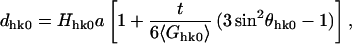
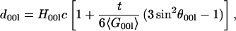
The most difficult problem in the Rietveld refinement is the existence of a deviatoric stress in DAC, because it can influence both the position and the shape of the reflections (5, 6, 32). At comparably low pressure (below 45 GPa), we conducted experiments in a soft pressure medium (Ar, CsI, CsCl, etc.), but at multimegabar pressures even helium could not provide hydrostatic conditions, and we did not use any pressure medium above 100 GPa. However, homogeneous heating above 1,000 K drastically reduces stresses (4, 32, 33) (Fig. 2b). To illustrate this statement we can use the equations of theory of diffraction at nonhydrostatic conditions (48). According to ref. 48, for a hexagonal sample under deviatoric stress condition, studied in the angle-dispersive mode with a loading direction parallel to the incident beam, one can write
 |
4a |
 |
4b |
where dhkl is the d-spacing, a and c are the lattice parameters, θhkl is the Bragg diffraction angle, t is the component of deviatoric stress, 〈Ghk0〉 and 〈G00l〉 are the average shear modulus in (hk0) and (00l) planes, respectively, Hhkl is the coefficient: H100 = √3/2, H110 = 1/2, H002 = 1/2, H004 = 1/4.
The expressions Δhk0 = d100/d110 − H100/H110 and Δ00l = d002/d004 − H002/H004 could be used to evaluate the stress state in the sample—if Δhk0 and Δ00l deviate from 0, material is under stress. For the sample compressed at ambient temperature to 273(2) GPa we obtained Δhk0 = 0.0082(3) and Δ00l = 0.0094(3); upon heating at 274(2) GPa and 640(10) K Δhk0 = 0.0084(3) and Δ00l = 0.0091(3); at 273(2) GPa and 840(10) K Δhk0 = 0.0011(3) and Δ00l = 0.0014(3), and at 273(2) GPa and 1,115(10) K Δhk0 = 0.0003(3) and Δ00l = 0.0002(3). In other words, with temperature increase at 273(2) GPa and 1,115(10) K, stresses in the sample vanish and an accurate structural refinement is possible (Fig. 2b).
Thermal vibration in hcp metals could be completely characterized by two anisotropic temperature factors, Ba and Bc (10). Our attempts to refine Ba and Bc separately for ɛ-Fe led to the same values within the accuracy of calculations. This result could mean that atomic thermal vibrations in ɛ-Fe are really close to isotropic, or that our powder diffraction data are not sensitive enough for the Rietveld refinement with anisotropic temperature factors.
Because the Rietveld refinement or the Wilson plot is sensitive to the
deviatoric stress, one may determine the temperature factor from the
temperature dependence of the integrated intensity of a reflection
I at a given pressure (10, 34, 35)
(Method II):
at a given pressure (10, 34, 35)
(Method II):
 |
5 |
(intensities are corrected for thermal diffusive scattering and T0 is the reference temperature). If the temperature factor is obtained by the Rietveld refinement method at a certain temperature T0 (for example, at high pressure and sufficiently high temperature, when deviatoric stresses are low), the temperature factor at another temperature could be found by using Eq. 2. We applied this method for (100), (002), and (101) reflections of ɛ-Fe (for those lines we were able to record full Debye rings) and found that the temperature factors, determined from any of those lines, are the same within the precision of measurements (Fig. 3a). Therefore, anisotropy of ɛ-Fe does not change significantly with increasing temperature (at least in the temperature range of our study up to ≈1,300 K).
Figure 3.

(a) Dependence of the difference between temperature
factor at temperature T (BT)
and 1,115 K (B1115) on
ln(I /I
/I ) for the (100),
(002), and (101) reflections of ɛ-Fe (for those lines we registered
full Debye rings). (b) Temperature factor of ɛ-Fe
determined by different methods (I or II) for 46 different P–T points.
Red hexagons present B obtained from the Rietveld
refinement (Method I). Continuous lines correspond to B
obtained for constant pressures by Method II. (c) Shear
waves Vs of ɛ-Fe found from temperature
factors (symbols are the same as in b).
(d) Compressional waves Vp of
ɛ-Fe found from temperature factors (symbols are the same as in
b).
) for the (100),
(002), and (101) reflections of ɛ-Fe (for those lines we registered
full Debye rings). (b) Temperature factor of ɛ-Fe
determined by different methods (I or II) for 46 different P–T points.
Red hexagons present B obtained from the Rietveld
refinement (Method I). Continuous lines correspond to B
obtained for constant pressures by Method II. (c) Shear
waves Vs of ɛ-Fe found from temperature
factors (symbols are the same as in b).
(d) Compressional waves Vp of
ɛ-Fe found from temperature factors (symbols are the same as in
b).
The temperature factor of ɛ-Fe was determined by the two methods for 46 different P–T points (Fig. 3b). The phonon density measurements of ɛ-Fe at pressures up to 42 GPa and ambient temperature conducted by Lübbers et al. (7) allowed for the extraction of information on mean-squared thermal displacements 〈x2〉, related to the Debye–Waller temperature factor B = 8π2〈x2〉. It is remarkable that mean-squared thermal displacements, which are usually difficult to reproduce by different methods (18, 20), came out reasonably close; at 42 GPa, for example, Lübbers et al. (7) reported 0.00203(7) A2, whereas our value at the same pressure is 0.0019(1) A2. [Note that the value given by Lübbers et al. (7) for α-Fe at ambient conditions, 0.00413(7) A2, significantly deviates from the value recommended by the Neutron Diffraction Commission of the International Union of Crystallography, 0.00443 A2 (20).]
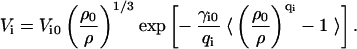
Measured at different pressures and temperatures, temperature factors of ɛ-Fe were used for calculating the Vs from Eq. 2 (Fig. 3c). Together with the data on KT, α, and dependence of Vs on molar volume (4, 16), we may also determine Vp (Fig. 3d). We should note that the thermal equation of state (4) provides the isothermal bulk modulus KT, which is related to the adiabatic bulk modulus as Ks = KT(1 + αγT) (α is the thermal expansion, γ the Grüneisen parameter). Numerical estimates show that differences between KT and Ks for ɛ-Fe (36) are less than 2% at temperatures lower than 1,400 K, introducing a negligible error in sound velocities calculated from Eq. 2. If the dependence of the Grüneisen parameter γ on volume has the form of γ = γ0(ρ0/ρ)q (ρ is the density, index 0 refers to the reference state 1 bar and 295 K, q is the constant) (16, 21), one can get the following equation for the sound velocity Vi (“i” could be “p” or “s” for compressional or shear waves, correspondingly)
 |
6 |
In Eq. 5 we used the acoustic γac approximation to the Grüneisen parameter γ: γac = 1/3(γp + 2γs) (16, 37). The results of determination of parameters of Eq. 5 by fitting all of the available data (Fig. 3) on sound velocities as a function of volume are presented in Table 1. We found that Eq. 5, with parameters from Table 1, reproduces data both on Vs and Vp with accuracy better than 1% and we used it for further extrapolation of the sound velocities to the conditions of Earth's inner core. At the temperatures of Earth's core (5,000–7,000 K) the electronic contribution together with lattice vibrations could affect the total Grüneisen parameter. However, according to the modern ab initio theoretical calculations (45) the lattice contribution dominates the total Grüneisen parameter at high compressions. For example, it was found (45) that the total and the lattice Grüneisen parameters were practically the same at 3,000 K and 280 GPa (extreme point probed by calculations in ref. 45). Based on the theoretical data in refs. 45 and 46 and our data for γac, we estimated maximum possible corrections in sound velocities at 330 GPa and 5,000 K as 2.5%. This value is well below the uncertainties associated with the theoretical calculations in refs. 45 and 46 or with the determinations of sound velocities from Eq. 2.
Table 1.
Parameters of Eq. 5 as obtained by fitting all available data on sound velocities as a function of volume
| Shear sound velocity | Compressional sound velocity | |
|---|---|---|
| γi0 | 1.549 (8) | 2.144 (38) |
| QI | 0.852 (18) | 0.656 (62) |
| Vi0 m/s | 3142 (28) | 5787 (26) |
| ρ0*, g/cm3 | 8.298 | 8.298 |
Fixed on value for P = 1 bar and T = 295 K (4).
The longitudinal wave velocities in iron to 110 GPa measured by inelastic x-ray scattering (47) are in quantitative agreement with our data (Fig. 4). At ambient temperature, aggregate sound velocities, obtained in the present study, are close to those found in refs. 5 and 8 to moderate pressures (≈100 GPa), but at higher pressures our value of Vs is lower and for Vp higher than the values in refs. 5 and 8. Such differences could be, for example, due to the effect of nonhydrostatic conditions (5, 8), which should be not so significant in our experiments, because samples were thermally relaxed. Still, although the mean values of sound velocities obtained in the present study and ref. 5 are different, the intervals of uncertainties are overlapping. For example, at 298 K and 211 GPa, the lowest estimated value of Vs in ref. 5 is 5.05 km/s, and the upper limit according to our data is 5.17 km/s. Theoretical calculations at 0 K (38–40) predict higher Vs, in comparison with our room- or high-temperature data, but our results (Fig. 3a) support comparably low anisotropy of ɛ-Fe as found by ab initio studies (40). The high temperature shock-wave Hugoniot sound velocities for ɛ-Fe to 200 GPa (41, 42) are close to our data (Fig. 4), but the difference becomes greater at high pressure because of high temperature along Hugoniot. Combining the Hugoniot data on Vp and Vs at 4,407 K and 200 GPa with low-temperature data from the present study, we estimated 1/Vp⋅ΔVp/ΔT = −2.3 10−5 K−1 and 1/Vs⋅ΔVs/ΔT = −3.9 10−5 K−1 in good agreement with phenomenological calculations by Stacey (36). Moreover, the acoustic Grüneisen parameter γac calculated from our data (Table 1) for 5,000 K and 330 GPa is equal to 1.207, which is close to the value of the Grüneisen parameter obtained directly from considerations of the physics of Earth's core and the Preliminary Reference Earth Model (PREM) (36, 43, 44). The large (4–6×) extrapolation of our data in temperature to the inner core conditions requires caution, because when close to the melting temperature the properties of a solid could change significantly. However, by using 1/Vp⋅ΔVp/ΔT and 1/Vs⋅ΔVs/ΔT estimated above, we can find Vp = 10.8(1.1) km/s and Vs = 3.9(4) km/s (29) at 350 GPa and 6,000 K; these are close to the PREM values of Vp = 11.18 km/s and Vs = 3.60 km/s. Considering the uncertainties in temperature and PREM values of sound velocities, and a possible change in the state of iron [in the inner core it could be β- or θ-phase (4, 10, 44)], agreement between PREM sound velocities and measured values is remarkable.
Figure 4.

Comparison of the present results (triangles) with theoretical (continuous lines) (8–40), static compression (open circles) (5, 9), inelastic x-ray scattering (open hexagons) (47), shock-waves studies (dotted lines) (41, 42), and with seismic observations (PREM) (43) in the inner core (crosses). Extrapolations of sound velocities to the inner core pressure at ambient temperature (based on Eq. 5, with parameters from Table 1) are shown by diamonds with errors bars. Estimation of sound velocities for the inner core conditions (350 GPa and 6,000 K), using 1/Vp⋅ΔVp/ΔT and 1/Vs⋅ΔVs/ΔT, are shown by red hexagons.
Acknowledgments
We appreciate the help of J. Hu in some x-ray experiments. The discussions with O. L. Anderson were useful. We thank the Brookhaven National Laboratory and European Synchrotron Radiation Facility for synchrotron beam time. Comments of three anonymous reviewers helped in improving the manuscript. We thank the Swedish Natural Science Research Council, Wallenberg Foundation, and the Crafoords Fund for financial support.
Abbreviation
- DAC
diamond anvil cells
Footnotes
This paper was submitted directly (Track II) to the PNAS office.
References
- 1.Mao H K, Wu Y, Chen L C, Shu J F, Jephcoat A P. J Geophys Res. 1990;95:21737–21747. [Google Scholar]
- 2.Huang E, Basset W A, Tao P. J Geophys Res. 1987;92:8129–8135. [Google Scholar]
- 3.Funamori N, Yagi T, Uchida T. Geophys Res Lett. 1996;23:953–956. [Google Scholar]
- 4.Dubrovinsky L S, Saxena S K, Tutti F, Rekhi R, LeBihan T. Phys Rev Lett. 2000;84:1720–1723. doi: 10.1103/PhysRevLett.84.1720. [DOI] [PubMed] [Google Scholar]
- 5.Mao H-K, Shu J, Shen G, Hemley R J, Li B, Singh A K. Nature (London) 1998;396:741–743. , and correction (1999) 399, 280. [Google Scholar]
- 6.Singh A, Mao H K, Shu J, Hemley R J. Phys Rev Lett. 1998;80:2157–2160. [Google Scholar]
- 7.Lübbers R, Grünsteudel H F, Chumakov A I, Wortmann G. Science. 2000;287:1250–1253. doi: 10.1126/science.287.5456.1250. [DOI] [PubMed] [Google Scholar]
- 8.Mao H K, Xu J, Struzhkin V V, Shu J, Hemley R J, Sturhahn W, Hu M Y, Alp E E, Vocadlo L, Alfe D, et al. Science. 2001;292:914–916. doi: 10.1126/science.1057670. [DOI] [PubMed] [Google Scholar]
- 9.Merkel S, Goncharov A F, Mao H K, Gillet P, Hemley R J. Science. 2000;288:1626–1629. doi: 10.1126/science.288.5471.1626. [DOI] [PubMed] [Google Scholar]
- 10.Willis B T M, Pryor A W. Thermal Vibrations in Crystallography. Cambridge, U.K.: Cambridge Univ. Press; 1975. [Google Scholar]
- 11.Hewat A W. J Phys C Solid State Phys. 1972;5:1309–1315. [Google Scholar]
- 12.Grimvall G. Thermophysical Properties of Materials. Amsterdam: Elsevier Science; 1986. [Google Scholar]
- 13.Kuhs W F. Acta Crystallogr A. 1992;48:4880–4898. [Google Scholar]
- 14.Dubrovinsky L S, Saxena S K, Dubrovinskaia N A, Rekhi R, LeBehan T. Am Mineral. 1999;85:386–390. [Google Scholar]
- 15.Dubrovinsky L S, Dubrovinskaia N A, Saxena S K, Rekhi R, LeBehan T. J Alloys Comp. 1999;297:156–161. [Google Scholar]
- 16.Anderson O L. Equation of State of Solids for Geophysics and Ceramic Science. New York: Oxford Univ. Press; 1995. [Google Scholar]
- 17.Guinan M W, Steinberg D J. J Phys Chem Solids. 1972;35:1501–1505. [Google Scholar]
- 18.Sears V F, Shelley S A. Acta Crystallogr A. 1991;47:441–446. [Google Scholar]
- 19.Peng L-M, Ren G, Dudarev S L, Whelan M J. Acta Crystallogr A. 1991;52:456–466. [Google Scholar]
- 20.Butt N M, Bashir J, Willis B T M, Heger G. Acta Crystallogr A. 1988;44:396–401. [Google Scholar]
- 21.Barron T H K, Leadbetter A J, Morrison J A, Salter L S. Acta Crystallogr. 1966;20:125–135. [Google Scholar]
- 22.DeWames R E, Wolfram T, Lehman G W. Phys Rev. 1965;138:717–726. [Google Scholar]
- 23.Schiffer J P, Parks P N, Heberle J. Phys Rev. 1964;133:1553–1568. [Google Scholar]
- 24.Skelton E F. J Appl Crystallogr. 1969;2:106–110. [Google Scholar]
- 25.Albanese G, Ghezzi C. Phys Rev B Condens Matter. 1973;8:1315–1322. [Google Scholar]
- 26.Grimvall S, Grimvall G. Acta Crystallogr A. 1968;24:612–614. [Google Scholar]
- 27.Alexopoulos K, Boskovits J, Mourikis S, Roilos M. Acta Crystallogr. 1965;19:349–355. [Google Scholar]
- 28.Dubrovinsky L S, Dubrovinskaia N A, Saxena S K, Annersten H, Hålenius E, Harryson H, Tutti F, Rekhi S, Le Bihan T. Science. 2000;289:430–432. doi: 10.1126/science.289.5478.430. [DOI] [PubMed] [Google Scholar]
- 29.Young R A, editor. The Rietveld Method. New York: Oxford Univ. Press; 1996. [Google Scholar]
- 30.Larson A C, Von Dreele R B. Los Alamos National Laboratory, LAUR. 1994. pp. 86–748. [Google Scholar]
- 31.Serizawa H, Arai Y, Takano M, Suzuki Y. J Alloys Comp. 1999;282:17–22. [Google Scholar]
- 32.Dubrovinsky L S, Saxena S K, Lasor P, Weber H-P. Science. 1998;281:5373. [Google Scholar]
- 33.Weidner D J, Wang Y, Vaughan M T. Geophys Res Lett. 1994;21:753–756. [Google Scholar]
- 34.Alexopoulos K, Boskovitis J, Mourikis S, Roilos M. Acta Crystallogr. 1965;19:349–353. [Google Scholar]
- 35.Dingle R E, Medlin E H. Acta Crystallogr A. 1972;28:22–27. [Google Scholar]
- 36.Stacey F D. Phys Earth Planet Inter. 1995;89:219–245. [Google Scholar]
- 37.Barron T H K. Ann Phys. 1957;1:77–89. [Google Scholar]
- 38.Stixrude L R, Cohen E. Science. 1995;267:1972–1975. doi: 10.1126/science.267.5206.1972. [DOI] [PubMed] [Google Scholar]
- 39.Soderlind P, Moriarty J A, Willis J M. Phys Rev B Condens Matter. 1996;53:14063–14072. doi: 10.1103/physrevb.53.14063. [DOI] [PubMed] [Google Scholar]
- 40.Steinle-Neumann G, Stixrude L, Cohen R E. Phys Rev B Condens Matter. 1999;60:791–801. [Google Scholar]
- 41.Brown J M, McQeen R G. J Geophys Res. 1986;91:7485–7494. [Google Scholar]
- 42.Duffy T S, Ahrens T J. In: High Pressure Research: Applications to Earth and Planetary Sceinces. Syono Y, Manghnani M H, editors. Tokyo: Terra Scientific Publishing; 1992. pp. 353–361. [Google Scholar]
- 43.Dziewonski A M, Anderson D L. Phys Earth Planet Inter. 1981;25:297–356. [Google Scholar]
- 44.Anderson O L. Phys Earth Planet Inter. 1998;109:179–197. [Google Scholar]
- 45.Wasserman E, Stixrude L R, Cohen E. Phys Rev B Condens Matter. 1996;53:8296–8309. doi: 10.1103/physrevb.53.8296. [DOI] [PubMed] [Google Scholar]
- 46.Stixrude L R, Wasserman E, Cohen E. J Geophys Res. 1997;102:24729–24739. [Google Scholar]
- 47.Fiquet G, Badro J, Guyot F, Requardt H, Krisch M. Science. 2001;291:468–471. doi: 10.1126/science.291.5503.468. [DOI] [PubMed] [Google Scholar]
- 48.Singh A K, Balasingh C. J Appl Phys. 1994;75:4956–4962. [Google Scholar]
- 49.Brown J M. J Appl Phys. 2000;86:5801–5808. [Google Scholar]
- 50.Ahrens J, editor. Mineral Physics and Crystallography. Washington, DC: Am. Geophysical Union; 1995. [Google Scholar]