Spontaneous pneumothorax is relatively common in the community.1 The incidence of iatrogenic pneumothorax is difficult to assess but is probably increasing due to the more widespread use of mechanical ventilation and interventional procedures such as central line placement and lung biopsy. Correct interpretation of chest radiographs in this clinical setting and knowledge of when to request more complex imaging techniques are essential. In this review we discuss the role of the chest radiograph in the assessment of pneumothorax before and after treatment along with the value of computed tomography and radiologically guided chest drain placement.
Sources and selection criteria
We reviewed textbooks of chest imaging and radiological normal variants. We also searched Medline for articles relating to both imaging appearances and clinical management of pneumothorax.
Pretreatment evaluation
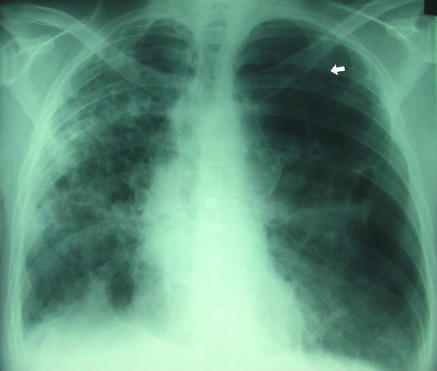
The radiographic diagnosis of pneumothorax is usually straightforward (fig 1). A visceral pleural line is seen without distal lung markings. Lateral or decubitus views are recommended for equivocal cases.2 On standard lateral views a visceral pleural line may be seen in the retrosternal position or overlying the vertebrae, parallel to the chest wall.3 Shoot-through lateral or decubitus views may be used in ventilated patients or neonates. Although the value of expiratory views is controversial4 many clinicians still find them useful in the detection of small pneumothoraxes when clinical suspicion is high and an inspiratory radiograph appears normal. The British Thoracic Society guidelines2 divide pneumothoraxes into small and large based on the distance from visceral pleural surface (lung edge) to chest wall, with less than 2 cm being small and more than 2 cm large. A small rim of air around the lung actually translates into a relatively large loss of lung volume, with a 2 cm deep pneumothorax occupying about 50% of the hemithorax.2 A large pneumothorax is an objective indication for drainage.2
Fig 1.
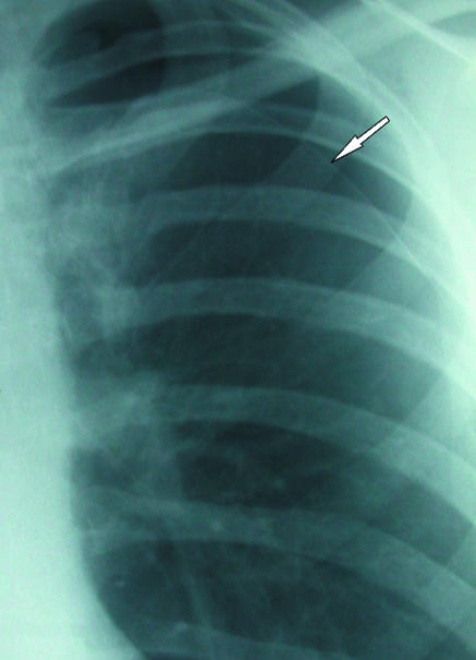
(left) Classic appearances of left sided pneumothorax with readily apparent visceral pleural line (arrow)
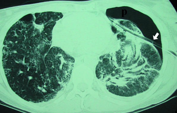
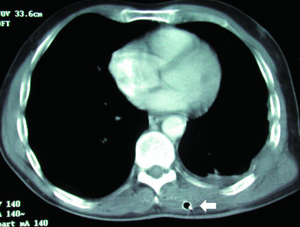
In the supine patient, air in the pleural space will usually be most readily visible at the lung bases (fig 2) in the cardiophrenic recess and may enlarge the costophrenic angle (the deep sulcus sign). Adherence of inflamed pleura to the chest wall may confine a pneumothorax to a loculated portion of the pleural space around the site of the air leak (fig 3). A drain placed remote from this area will be ineffective at best. If the operator enters the chest at a site of adherent pleura, parenchymal damage and a severe air leak may follow (fig 4). For this reason, in the authors' opinion, loculated pneumothoraxes are best approached under direct fluoroscopic and occasionally computed tomography guidance. Emphysematous bullae may alsomimic a loculated pneumothorax, particularly when there is a background of chronic lung disease. Sometimes internal lung markings are visible in a bulla using a bright light. If there is clinical doubt in a patient with symptoms then computed tomography is helpful.
Fig 2.
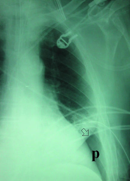
(right) Supine projection showing air collected at lung base. Absent lung markings and a visceral pleural line (arrow) are still visible (P=pneumothorax). Left basal chest drain is noted
Fig 3.
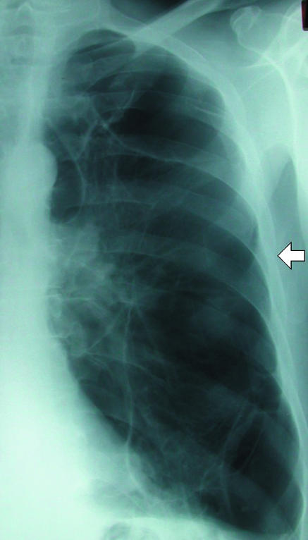
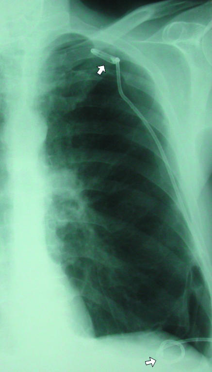
(left) Loculated left sided pneumothorax in a patient with severe chronic obstructive airways disease. Placement of chest drain into fifth intercostal space (arrow) might have entered lung parenchyma and would most likely not have achieved complete drainage of this loculated collection. (right) Percutaneous pigtail catheters (arrows) placed in apical and basal components of pneumothorax under fluoroscopic guidance. After several days of drainage the lung re-expanded completely
Fig 4.
Extensive pulmonary fibrosis and left pneumothorax (p) treated by blind chest drain placement. Axial computed tomograpy shows that drain (arrow) has traversed lung parenchyma. This led to a deterioration in patient's clinical condition
Summary points
A large pneumothorax is radiographically defined as one with > 2 cm from pleural surface to lung edge; this is an objective indication for drainage
In the supine patient, pneumothoraxes are best seen at the lung bases and adjacent to the heart
Skin folds, companion shadows, the scapula, and previous lung surgery or chest drain placement may all mimic pneumothoraxes
Blind chest drain placement into a loculated pneumothorax may lead to an iatrogenic air leak from direct trauma to the pleura, worsening the patient's clinical condition
An immediate post-treatment radiograph is essential to detect complications and ensure a satisfactory drain position
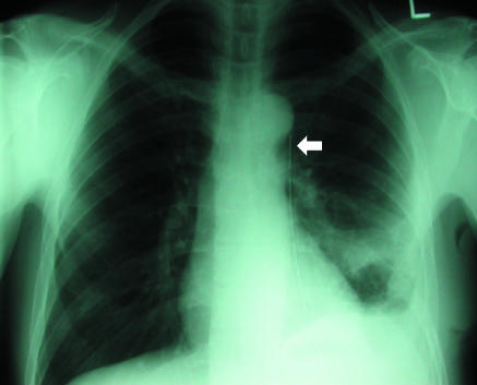
The chest radiograph should also be carefully examined for evidence of underlying parenchymal lung disease (fig 5). The most common of these predisposing to pneumothorax are emphysema, pulmonary fibrosis of any cause, cystic fibrosis, aggressive or cavitating pneumonia, and cystic interstitial lung diseases such as Langerhans' cell histiocytosis and lymphangiomyomatosis. Detection of an underlying condition is important for several reasons. Firstly, therapy of the parenchymal lung disease may be possible. Secondly, unlike primary spontaneous pneumothorax, patients with secondary air leaks are not candidates for early discharge and require inpatient observation.2 Finally, all but the smallest (defined as apical or less than 1 cm in depth) secondary pneumothoraxes require treatment, even when symptoms are minimal.2
Fig 5.
Background fibrotic lung disease (underlying ulcerative colitis), which places patient at risk of secondary pneumothorax. Although medial border of scapula (arrow) is easily recognisable as such on this radiograph it can sometimes be misinterpreted as a visceral pleural line
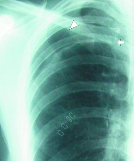
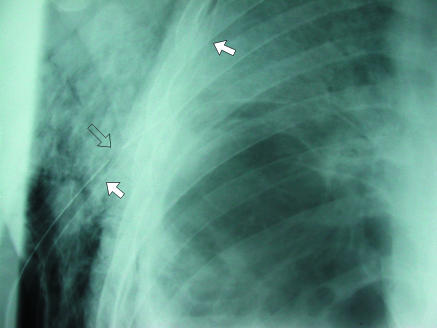
Several well known artefactual appearances can mimic the presence of a pneumothorax and should always be remembered during evaluation of a chest radiograph. The medial border of the scapula can imitate a lung edge but once considered can be traced in continuity with the rest of the bone, revealing its true nature (fig 5). Skin folds overlying the chest wall (fig 6) can simulate a visceral pleural line and with the relative lack of lung markings in the upper zones can lead to erroneous diagnosis, particularly in children. Once considered, however, their true nature is readily apparent. Skin folds are usually seen to pass outside the chest cavity, are straight or only minimally curved, and do not run parallel to the chest wall as with a true visceral pleural line. If closely scrutinised, distal lung markings are seen. Clothing or bed sheets may produce a similar artefact. Skin folds also form a dense line—sharp on one side and blurred on the other—in contrast to the less dense visceral pleural line. The latter distinction can, however, be rather subjective. Occasionally, doubt persists. In this situation, repeat radiography after removal of clothing and repositioning of the arm will be conclusive. Radio-opaque lines are often seen accompanying the inferior margins of ribs, which may simulate a visceral pleural line. These are often called companion shadows although some restrict this term to densities accompanying the first and second ribs.5,6 They are caused by protruding extrapleural fat or the subcostal groove. This normal variant is characterised by its faithful relation to the inferior margin of the accompanying rib, whereas visceral pleural lines diverge from the rib to parallel the chest wall. Although usually close to the adjacent rib, companion shadows may sometimes protrude inferiorly for a variable distance, giving a confusing appearance (fig 7). After pleurectomy for recurrent pneumothorax a radio-opaque line may be visible at the operative site due to suture material or staples (fig 8). This may be misinterpreted as a new air leak, especially if compared with preoperative radiographs or in ignorance of the history of previous surgery.
Fig 6.
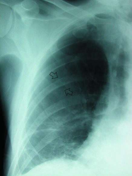
(left) Skin folds (arrows) overlying right hemithorax. Distal lung markings are readily apparent. Note folds are relatively straight unlike curved visceral pleural line of pneumothorax
Fig 7.
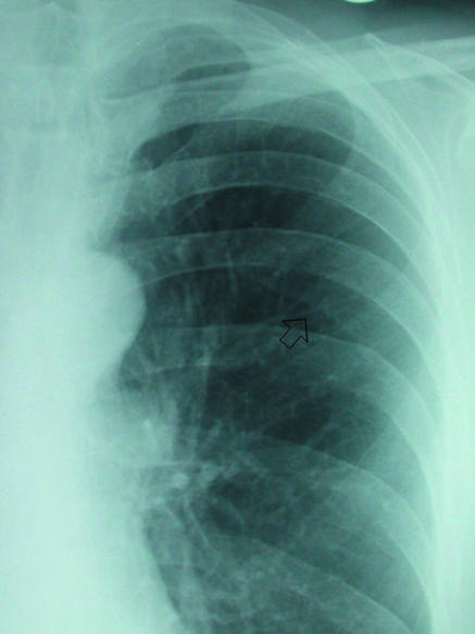
(right) Prominent companion or accompanying shadow below left sixth rib (arrow). Line is relatively parallel to accompanying rib, and distal lung markings are evident
Fig 8.
This patient underwent pleurectomy for recurrent pneumothorax. Suture material at right apex (arrow) is thicker than visceral pleural line and should not be confused with recurrent air leak. Compare with adjacent apical pneumothorax (arrowhead)
Post-treatment evaluation
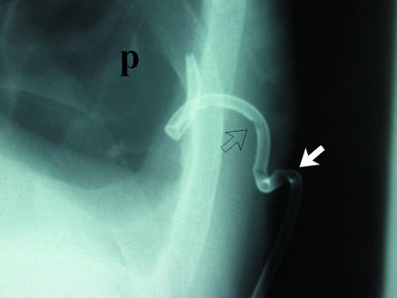
A post-drainage chest radiograph is essential after intervention to document resolution of the pneumothorax, detect complications, and ensure a satisfactory drain position. If tissue dissection at a drain insertion site is too superficial, a subcutaneous or intramuscular plane may be identified by the operator's finger and lead to drain placement outside the pleural space in an ineffective position. This is more likely to occur if the drain is sited at a posterior location, and subsequent radiographic position may appear satisfactory on the frontal film (fig 9). A lateral view or computed tomography examination will detect this problem. An adequate length of drain must also be inserted so that all side holes are contained within the pleural space. Failure to do so leads to inadequate drainage and air passage into subcutaneous tissues. The length of the tube with side holes can be identified on standard surgical chest drains by a gap in the radio-opaque marker line (fig 10). After satisfactory resolution of the pneumothorax, the drainage catheter can be removed and a further follow-up radiograph obtained to detect recurrence. A straight radio-opaque line is occasionally seen here along the line of the removed tube, known as a “drain track” (fig 11). This may be misinterpreted as a recurrent air leak, but its straight course and precise relation to the drain position on the radiograph before removal are usually conclusive. Presumably this finding is due to indentation of the pleura by the drain.
Fig 9.
(top) Chest radiography shows unremarkable appearance of intercostal drain (arrow), apart from its medial location. (bottom) Axial computed tomography shows drain (arrow) is located in subcutaneous tissues. More superior images showed that the drain terminated in this superficial position
Fig 10.
(top) Two large bore chest drains in a patient who developed a pneumothorax secondary to cavitating pneumonia. Lower drain (white arrows) is satisfactorily sited, but upper drain (open arrow) has side holes protruding into subcutaneous tissues, leading to extensive air leak. (bottom) Small pigtail catheter inserted into basal pneumothorax (p). Progressive traction on drain has led to extrusion of side holes into subcutaneous tissues (open arrow) and through skin surface (white arrow)
Fig 11.
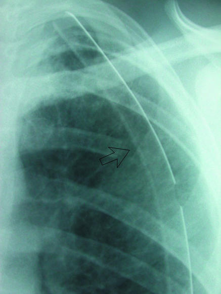
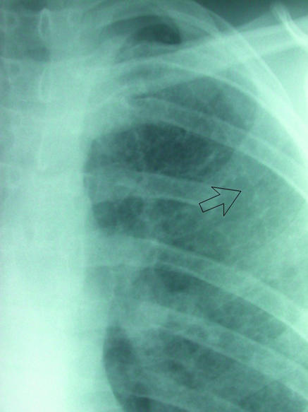
(left) Left apical chest drain (open arrow) in satisfactory position after lobectomy. (right) Chest radiograph after removal of drain next day shows faint radio-opaque line (arrow), known as a “drain track.” This was seen to resolve on subsequent radiographs
After placement of a chest drain, the tubing is connected to an underwater seal or flutter valve.7 The patient usually undergoes daily chest radiography until the pneumothorax has resolved. Care must be taken to ensure that an unclamped chest drain bottle is not placed on the trolley above the level of the patient's thorax during the trip to the x ray department. This may result in accumulation of air and fluid in the pleural space, producing a hydropneumothorax on the radiograph. If the drain bottle is later returned to a dependent position without the physician's knowledge, then inappropriate suction or additional drainage procedures may be carried out. This possibility should be considered in unexpected deterioration on radiographs, especially in the absence of clinical signs. Questioning the patient may be helpful. This problem can be prevented by emphasising to nursing and portering staff the importance of the bottle position.
Additional educational resources
American College of Chest Physicians (http://www.chestnet.org/education/cs/pneumothorax/interactive/index.php)—superb interactive site providing information on many of the practical aspects of management of pneumothoraxes that are often passed over in other reviews
British Thoracic Society (http://www.brit-thoracic.org.uk/c2/uploads/PleuralDiseaseSpontaneous.pdf)—guidelines for the management of spontaneous pneumothorax
American College of Chest Physicians consensus panel (http://www.chestnet.org/education/cs/pneumothorax/qrg/index.php)—interesting to compare the views of this panel with those of the British Thoracic Society guidelines
British Thoracic Society (http://www.brit-thoracic.org.uk/c2/uploads/PleuralDiseaseChestDrain.pdf)—guidelines for insertion of a chest drain
Radiological anatomy (http://www.radquiz.com/Chest.htm)—links to many excellent resources on chest radiology
Patient information
Aetna InteliHealth (http://www.intelihealth.com/IH/ihtIH/WSIHW000/9339/23666.html)—description of pneumothorax and details of treatment and prognosis, with links to other similar sites
Clamping of the chest drain before radiography is often carried out to detect small air leaks. British Thoracic Society guidelines7 do not generally recommend this but consider it acceptable under the supervision of trained nursing staff in the ward environment. The merits of clamping of the drain are, however, a matter of some controversy among chest specialists.8
Computed tomography
The main indication for computed tomography in this clinical setting is to distinguish an emphysematous bulla from a pneumothorax, which can be difficult on standard radiographs. High resolution computed tomography may also be helpful when underlying parenchymal lung disease is suspected but not clearly identified or characterised by a chest radiograph. Extrapleural or intrapulmonary catheter placement is readily seen on computed tomography. Cross sectional imaging guidance is occasionally necessary for drainage of loculated pneumothoraxes in difficult locations.
Drainage under radiological guidance
Loculated pneumothoraxes are best approached by direct needle puncture under fluoroscopic guidance. The patient can usually be positioned supine under the image intensifier, making the approach more comfortable for patient and operator. Small apical pneumothoraxes in patients with chronic lung disease who may have pleural adhesions can be approached through the axilla with the patient sitting on a stool and the image intensifier rotated for an anteroposterior projection. Occasionally a lateral approach is not possible, in which case anterior chest wall puncture in a sitting patient is required in the second or even first intercostal space (fig 12). Small pigtail drains of 8-10 French gauge with locking suture devices are the most commonly placed radiological catheters in our department. They are cosmetically acceptable, more comfortable than large bore 20 or 28 French gauge tubes, and are easier to site satisfactorily in small air collections. In addition, small bore catheters have been shown to be as effective as larger drains in the treatment of pneumothorax.2 Traction on small non-sutured catheters by the drain bottle may, however, lead to progressive extrusion, with prolapse of side holes. If such drains are used, they should be well supported with tape and adhesive dressing. A securing suture should be placed around the catheter if the drain is to be placed for a long period (more than 24 hours) or the patient is uncooperative.
Fig 12.
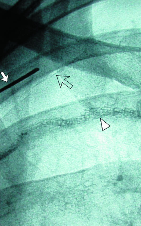
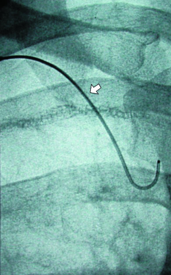
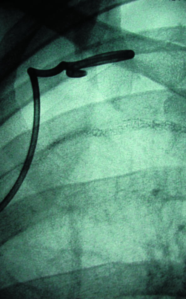
(left) Small pneumothorax post-pleurectomy at right apex (open arrow). Fluoroscopic guided needle puncture (white arrow) is being carried out. This unusual approach through the first intercostal space could damage subclavian vessels, which can be avoided by preliminary ultrasound examination of the needle path (arrowhead=suture material). (centre) Wire (arrow) is placed through the needle after aspiration of air. (right) Pigtail catheter coiled in pneumothorax and connected to underwater seal
Contributors: ARO wrote the first draft of the article, which was reviewed and edited by WEM. Patients were under care of either or both authors. ARO is guarantor for the paper.
Funding: None.
Competing interests: None declared.
References
- 1.Melton LJ, Hepper NG, Offord KP. Incidence of spontaneous pneumothorax in Olmsted County, Minnesota: 1950 to 1974. Am Rev Respir Dis 1979;120: 1379-82. [DOI] [PubMed] [Google Scholar]
- 2.Henry M, Arnold T, Harvey J. BTS guidelines for the management of spontaneous pneumothorax. Thorax 2003;58(Suppl 2): ii39-52. [DOI] [PMC free article] [PubMed] [Google Scholar]
- 3.Glazer H, Anderson DJ, Wilson BS, Molin PL, Sagel SS. Pneumothorax: appearances on lateral chest radiographs. Radiology 1989;173: 707-11. [DOI] [PubMed] [Google Scholar]
- 4.Seow A, Kazerooni EA, Pernicano PG, Neary M. Comparison of upright inspiratory and expiratory chest radiographs for detecting pneumothoraces. Am J Roentgenol 1996;166: 313-6. [DOI] [PubMed] [Google Scholar]
- 5.Kurihara Y, Yakushiji YK, Matsumoto J, Ishikawa T, Hirata K. The ribs: anatomic and radiologic considerations. Radiographics 1999;19: 105-19;151-2. [Quiz.] [DOI] [PubMed] [Google Scholar]
- 6.Meholic A, Ketai L, Lofgren R. Fundamentals of chest radiology. Philadelphia: WB Saunders, 1996: 29-31.
- 7.Laws D, Neville E, Duffy J. BTS guidelines for the insertion of a chest drain. Thorax 2003;58: 53-9. [DOI] [PMC free article] [PubMed] [Google Scholar]
- 8.Baumann MH, Strange C, Heffner JE, Light R, Kirby TJ, Klein J, et al. Management of spontaneous pneumothorax. An American College of Chest Physicians Delphi consensus statement. Chest 2001;119: 590-602 [DOI] [PubMed] [Google Scholar]


